13. INTERFACE AND APPLICATION PROGRAMMING
I have done this assignment outside the corresponding week, in which in Spain we were in a state of confinement due to health alarm. I was also ill.
So I have done this task after I have finished and presented my final work, and therefore I have already created my own board that controls the security device that I have developed for my final project. And also input and output boards.
The statement of this assignment is as follows:
Individual assignment:
Write an application that interfaces a user with an input &/or output device that you made.
Group assignment:
Compare as many tool options as possible.
*In this case, unlike other weeks, I have developed individual work before group work, which I usually do with my partner Álvaro. *
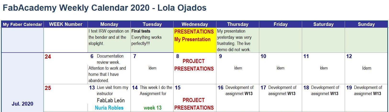
This is the schedule that I have followed this week:
13.1. INDIVIDUAL ASSIGNMENT
This week I have to make an application with a user interface that communicates with inputs or outputs of a device made by me.
First of all, I am going to think about how to develop this assignment, what program to use, how to access it and what I can do with the program I decide to use.
I look for information and documentation about it in assignments of students from other years of FabAcademy and I also consult with my classmates and instructors that when the class in which this assignment was carried out they gave us clues on how to approach its development.
I have already decided.
I’m going to do something using the Processing software.
I had never used it, and I like it because it is simple, although it requires a bit of programming skill, but there is a lot of information online.
First, I watch a video in which Marta Verde explained to FabLab León students from last year how to use Processing. Thank you very much Marta for this very useful contribution.
13.1.1. Access to the Processing program
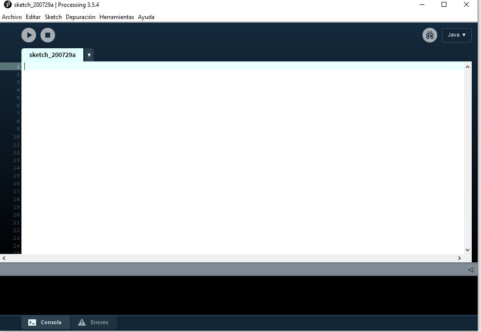
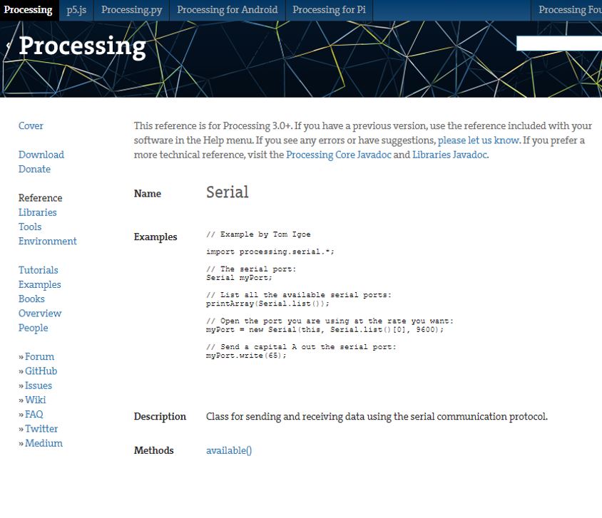
First I download the program at the following link.
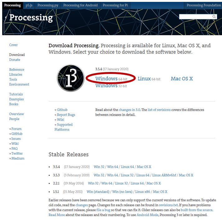
I download it, unzip it and run it, the screen I have is this:
Processing programming uses C language. For reference, like my partner Adrián Torres of FabLab León, I use the following Make book: Getting Started with Processing and the Open Lab Cheat Sheet.
As in the Arduino IDE the first thing we do is declare some Variables and Libraries.
I access and download the necessary libraries to work with processing for my purpose:
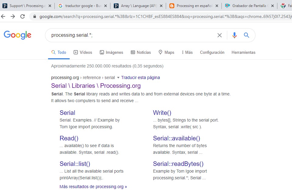
It is important to use the processing.serial library then we have the Void Setup where we define the work area (runs only once) and finally the Void Draw where we draw the elements that we are going to use the processes (runs repeatedly during the execution).
13.1.2. Programming script
For this week’s assignment and the program I want to do, first I see what I have.
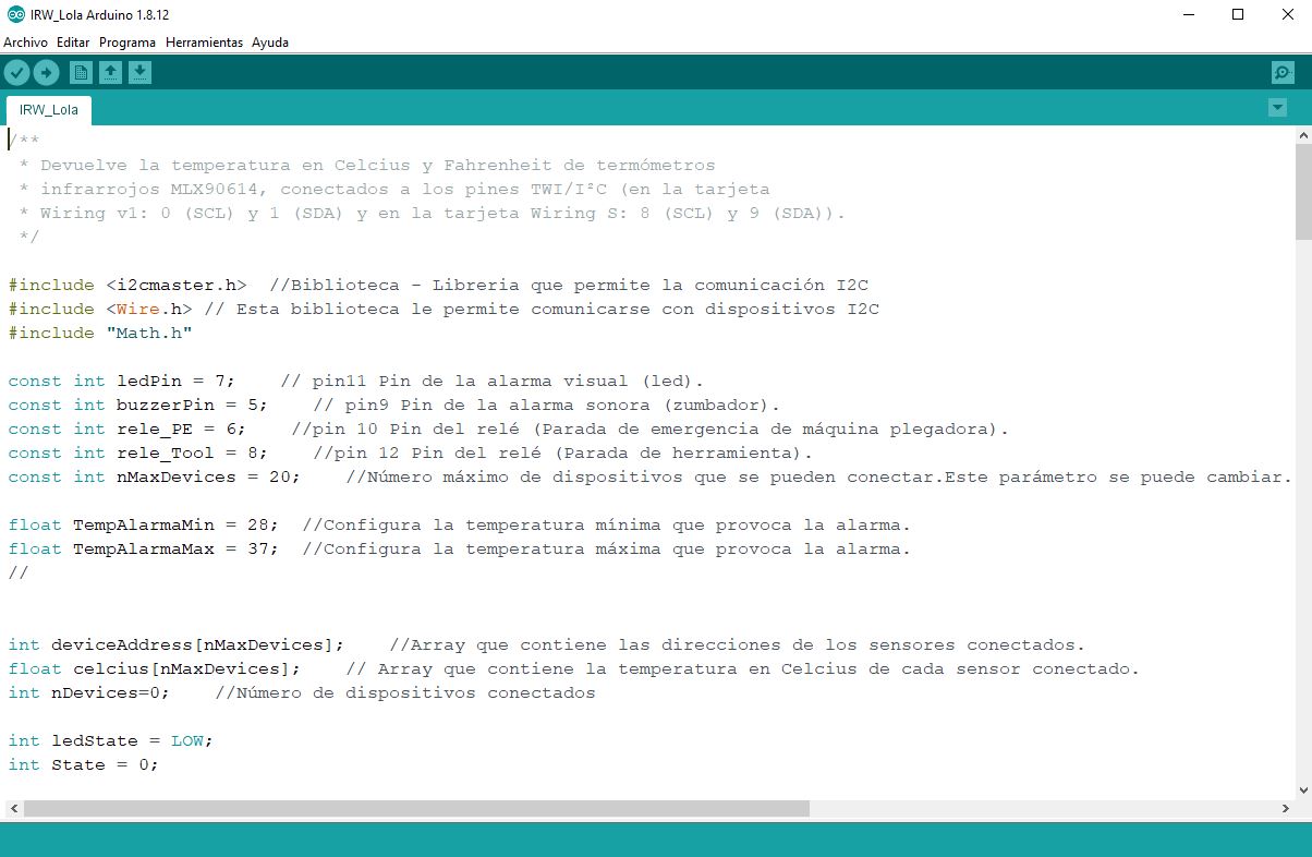
• I have my final project and in it I made an electronic control box with the ATMega328 microcontroller.
• I have my programming in Arduino IDE.
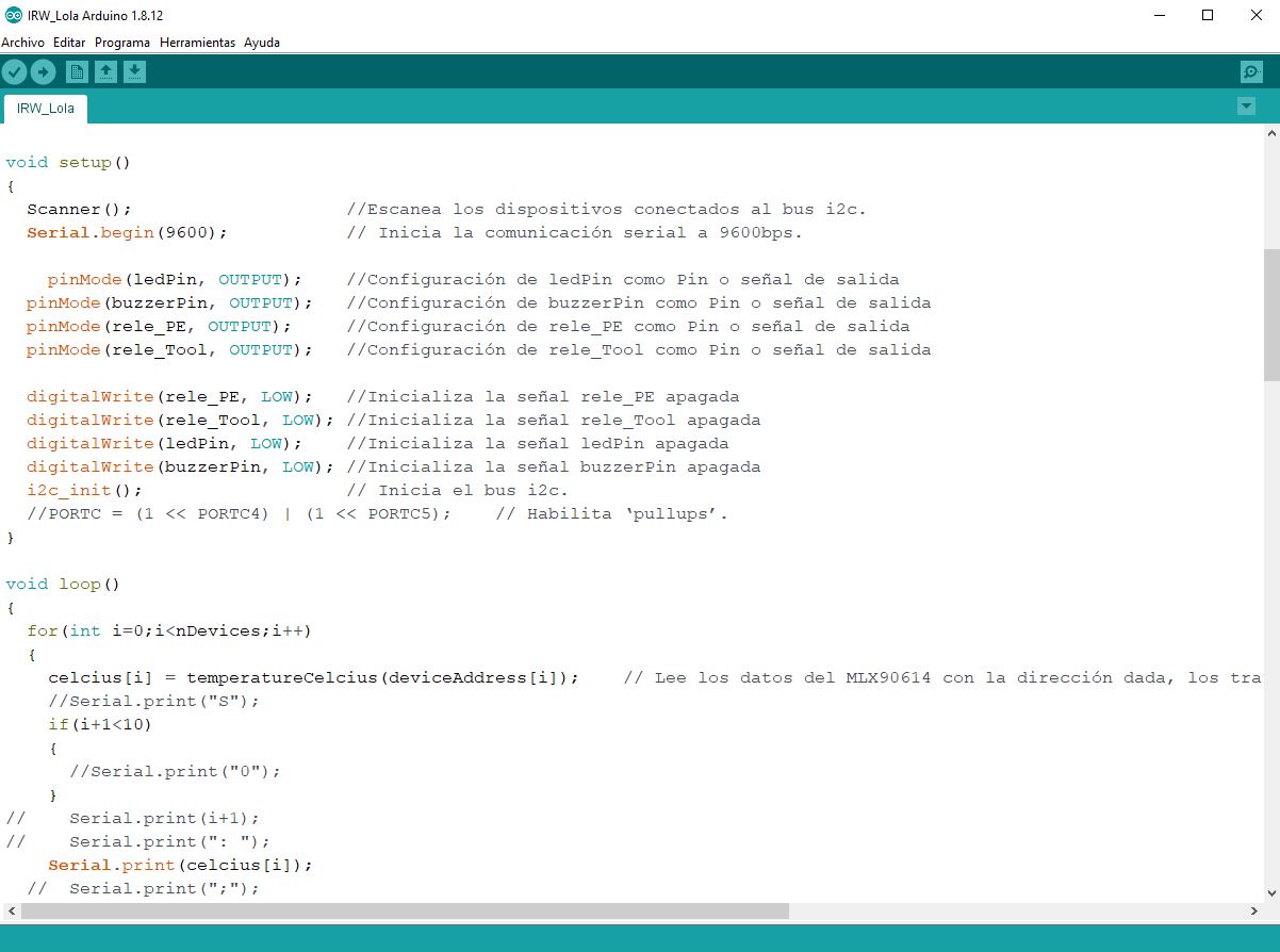
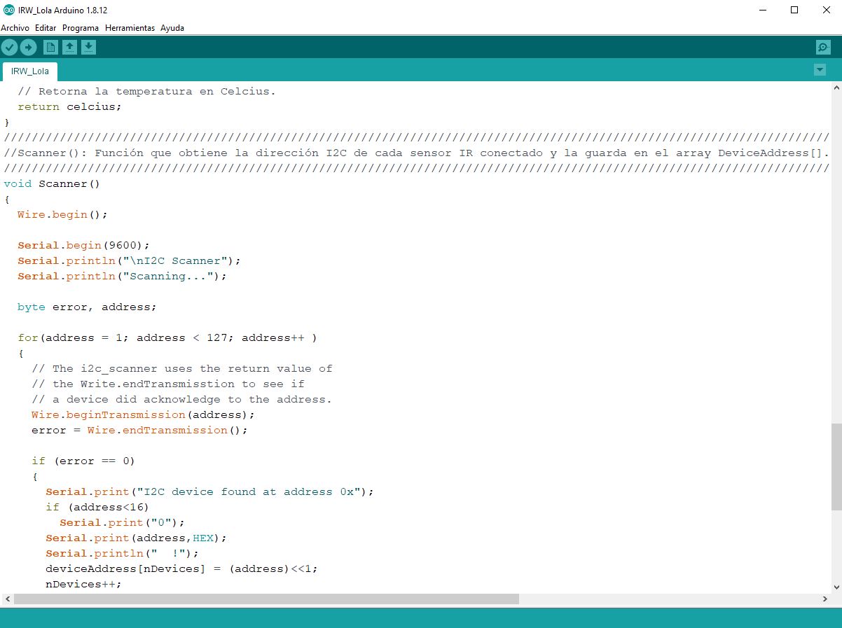
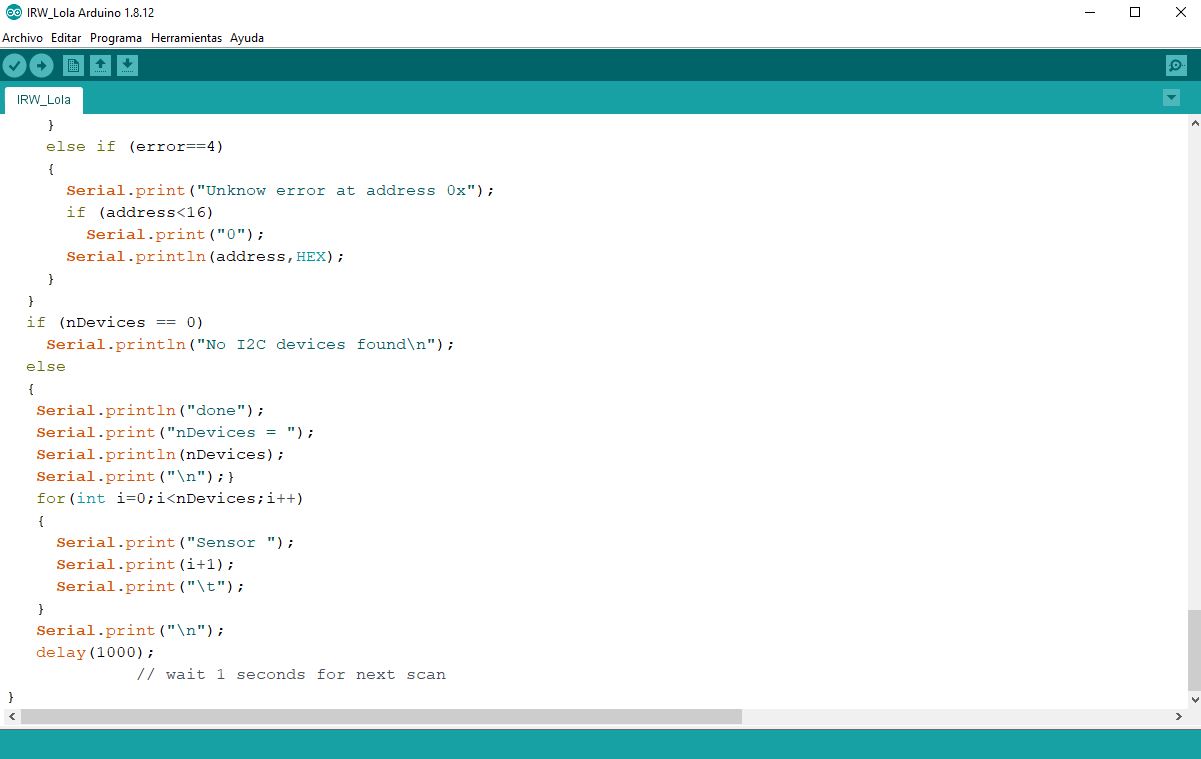
• I have the I2C communication bus with which the sensor reading is sent through the serial port.
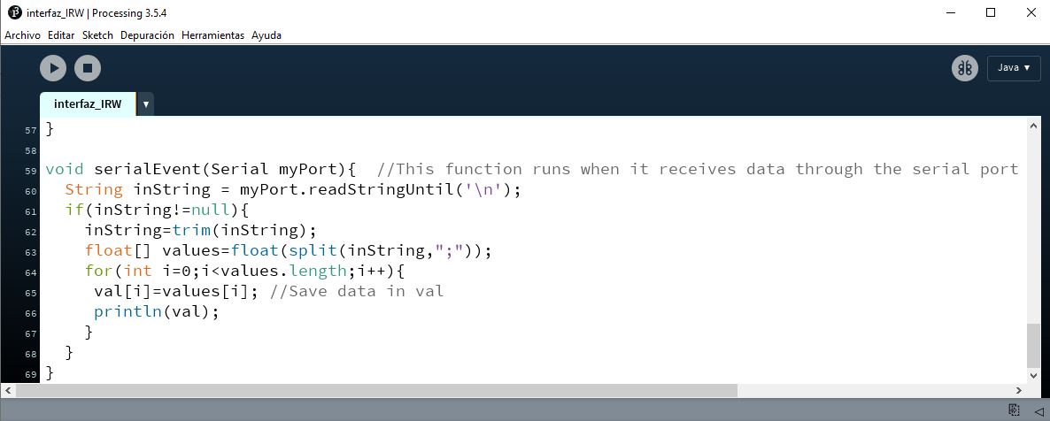
To make the interface in Processing, first I modify the programming so that the reading of the 11 sensors, mounted on the IRW Safety Device, is sent as a vector.

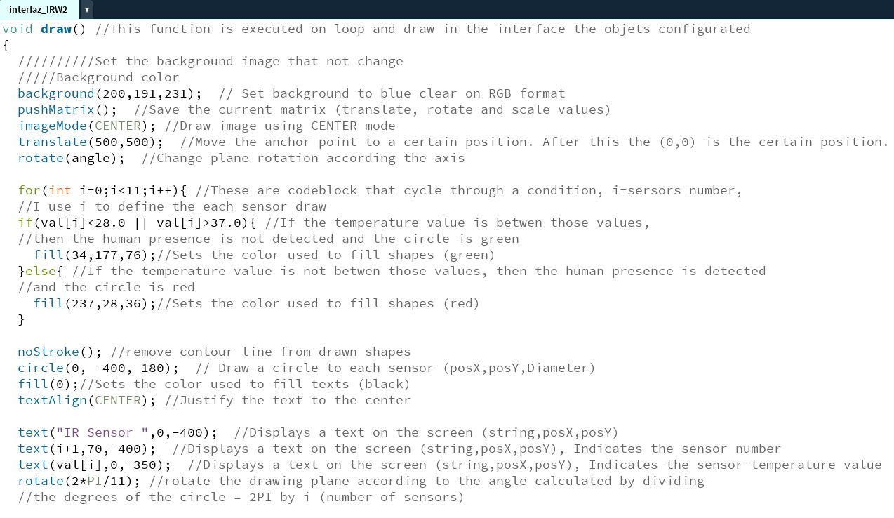
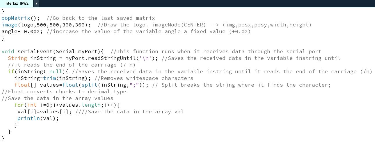
Then I make the script to perform the function that I have proposed, which is summarized as follows:
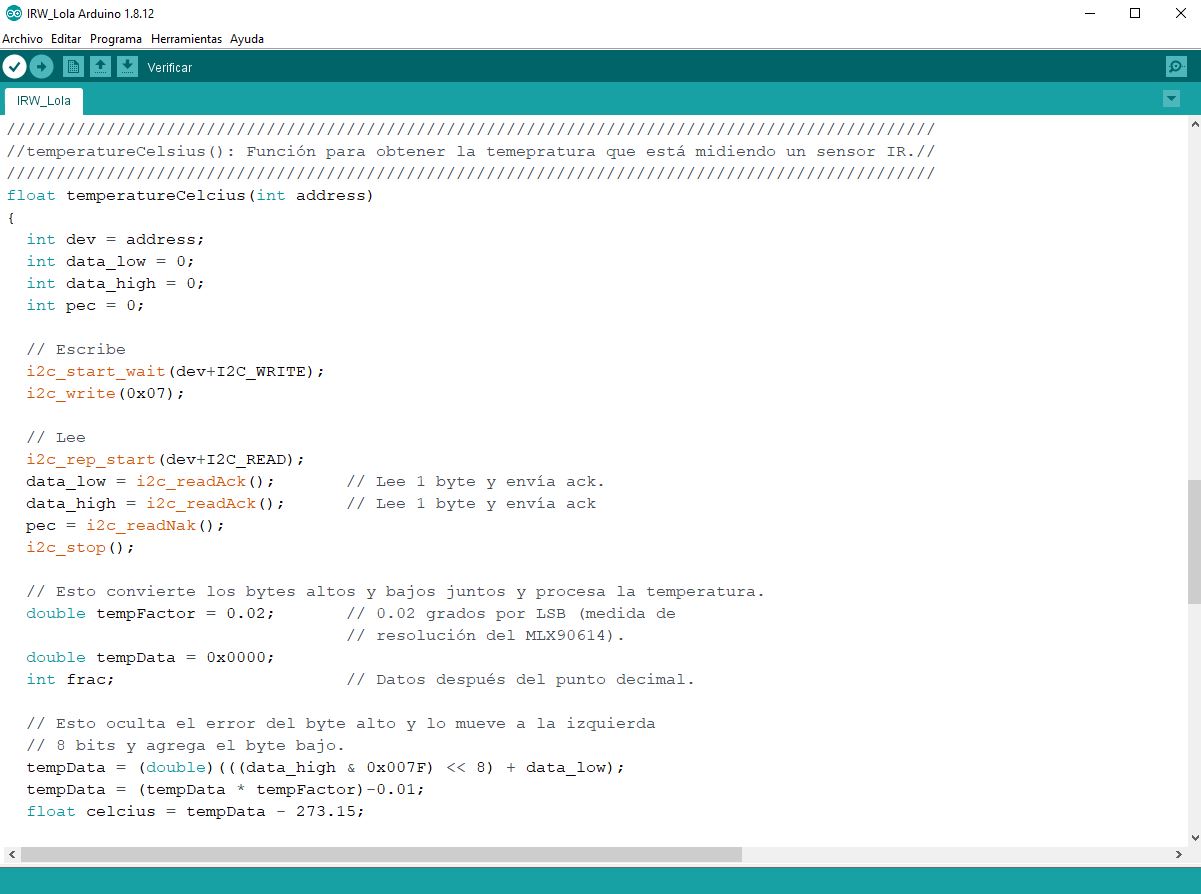
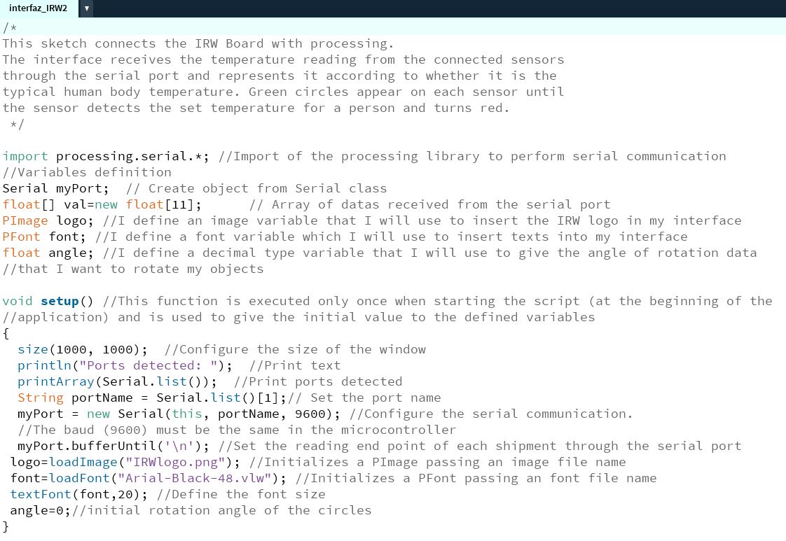
The interface receives the temperature reading from the connected sensors through the serial port and represents it according to whether it is the typical temperature of the human body.
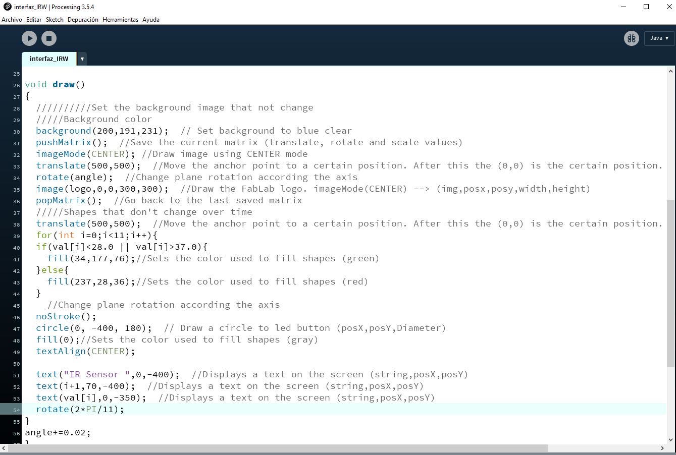
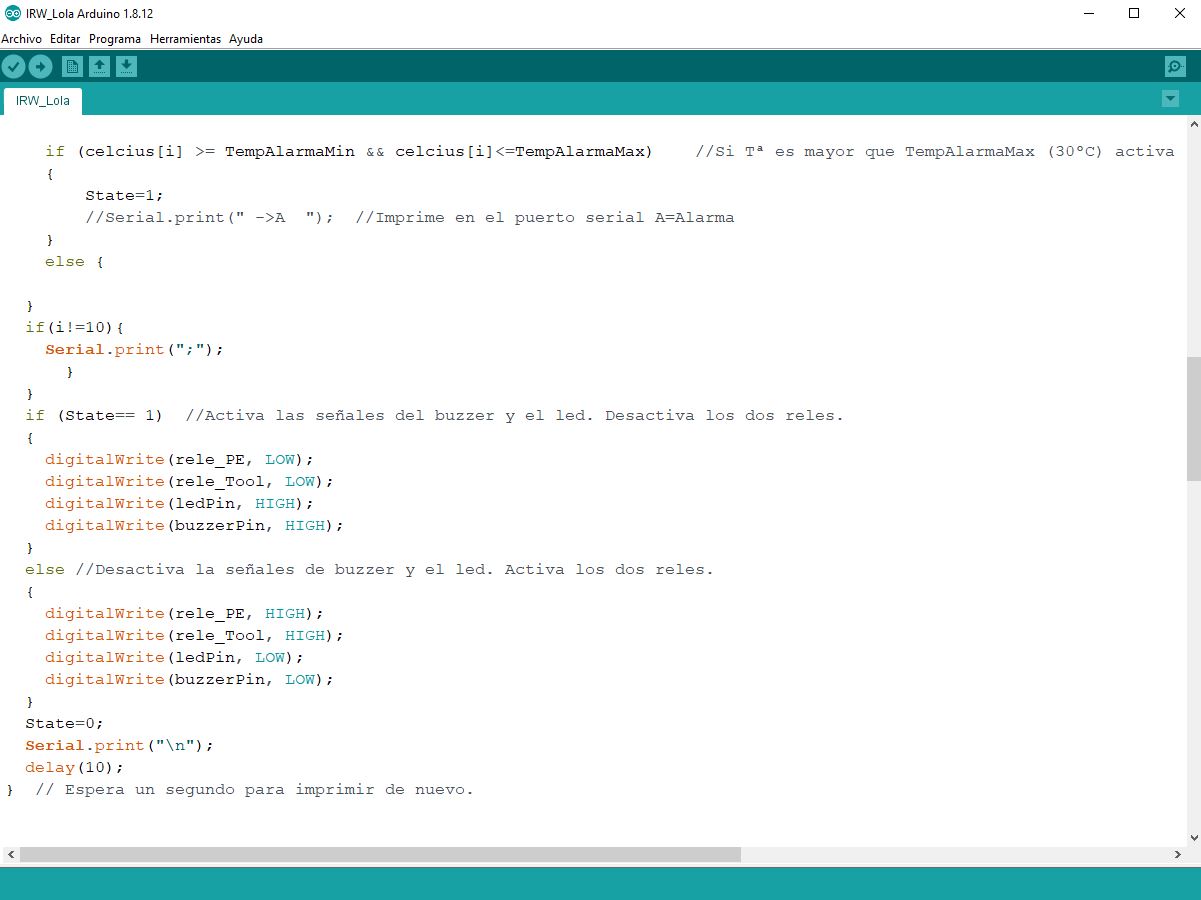
The circles configured for the reading of each sensor appear in green color until the sensor detects the temperature set in the programming as the typical temperature of the human body, which would be the one that a person who could cross the critical zone of danger of the machine, in this case the circle corresponding to the sensor that detects this temperature will turn red.
Then I introduce an image that symbolizes the device, use the IRW logo created for my final project, and finally play with the movement of the shapes in the interface.
The file resulting from the programming is Link to Arduino CODE for Processing.
To load the programming I need the i2cmaster.h library and my board that is in the control box of the IRW device and which I have given the name of IRW Board .
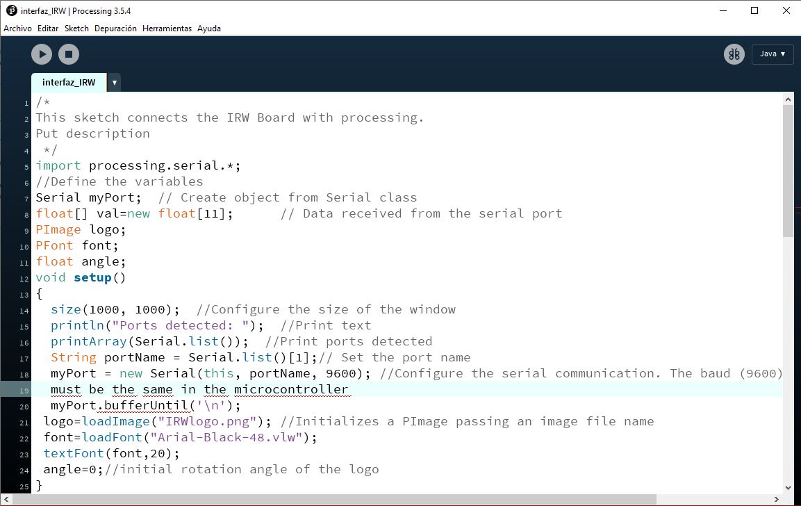
I check the port that the IRW Board has, it is the Com5 port, I impose VARIABLES such as the communication speed with a value of 9600 baud / s.
As it is summer and it is hot, the temperature to be set for the human presence to be detected varies and the values set now are between 28 and 37 degrees Celsius.
For the display of the interface created in processing, I indicate a background color with an RGB code.
All the steps are left in the comments of the processing script.
The Arduino programming used is the one that I have configured for my IRW safety device in my final project to work. On it I make the necessary modifications that I have indicated before and everything can be consulted in the link file to Arduino CODE for Processing, which is the one that I have generated now for this assignment and is higher.
To configure the display of what I want to show, I can choose the way to display the texts associated with each of the shapes that I want to appear, as well as the colors and characteristics. In the case of texts, I can choose their display by assigning it a calligraphic font.
So I load the font that I want to use to display the entered texts.
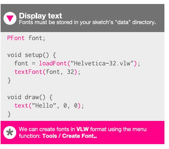
In what appears in pink (Tool / Create Font) the file of the font that I choose is imported / created and saved in the data folder (created by me) of the processing project.
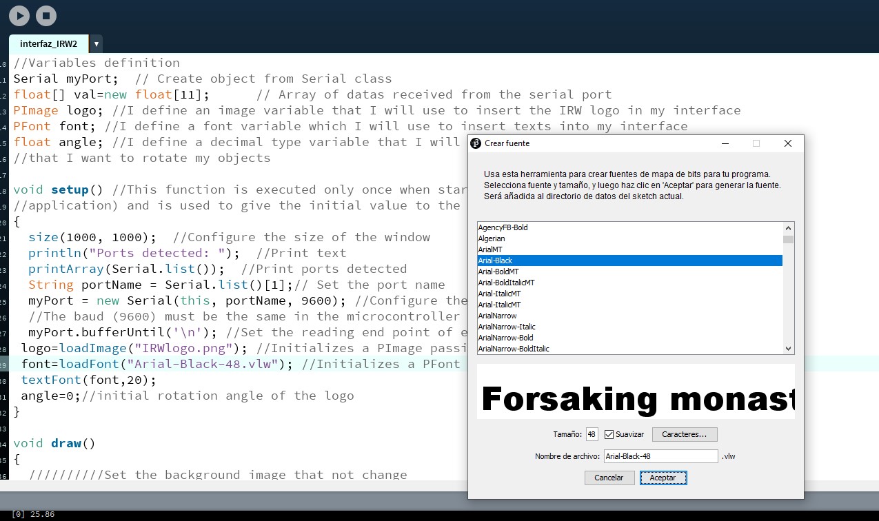
Important note: To insert an image, it must be saved in the same data folder.
In my case the image IRWlogo.png

Image is defined as variable in script before void setup.
I am going to put it centered on my display and the circles that represent the surrounding sensors with the temperature measurement they detect and the color green if the temperature is not conflictive and red if the temperature read by the sensor is critical.
I’m having problems:
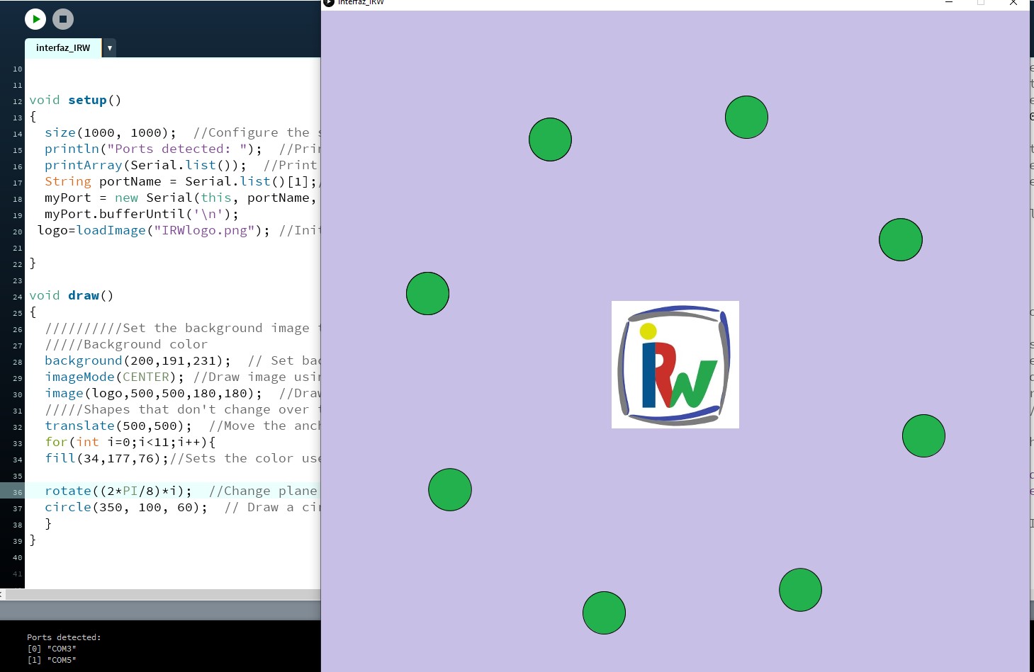
To draw the number of circles according to the number of sensors I have, the maximum number that the display recognizes is 8 and they don’t like odd numbers, it does what it wants …
I will have to check my code in case I am doing something wrong.
I want to show 11 sensors and what I get are things like this:
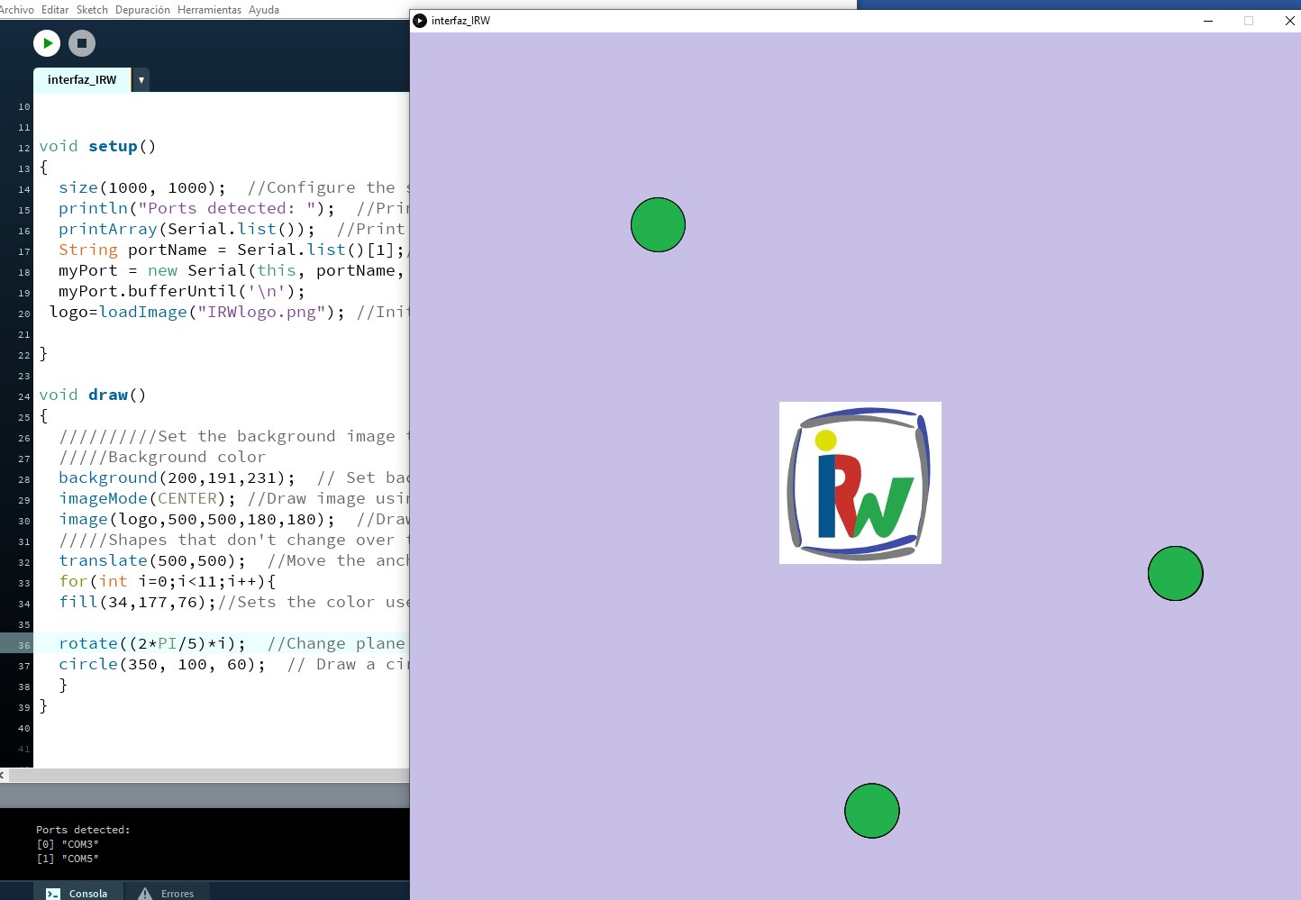
After reviewing everything I have detected a form error in this command:
And … I’ve already solved it :)
13.1.3. Resulting interfaces
The following videos show the results obtained for various configuration tests of the graphical interface to show when my IRW safety device is working.
• First test run of temperature reading of the 11 IRW sensors.
• Test of color change of the circles that represent the sensors when a hand invades the danger zone of the machine and the IRW detects it and acts.
• Test by adding a turning motion to the circles around the IRW logo.
• Test by adding a turning motion to the IRW logo and keeping the circles static.
In this final video you can see the operation of the IRW Safety Device as well as the display on the computer screen of the interface created in Processing for this assignment.
Script corresponding to the final video (Link to Processing Script) :
I love the result!! and the fact that I achieved this when I had no starting knowledge when starting this assignment. :)
13.2. GRUPAL ASSIGNMENT
The Group Assignment page is at the following link.
I did this group assignment with my partner Álvaro during confinement, we did it by videoconference and due to the existing limitations in reality what we did was study the possibilities of three different softwares for the creation of graphical user interfaces to control devices or to manage their operation or show their performance on machines or elements to which they are connected or have to be monitored.
The softwares compared were Unity, Processing and App Inventor.
There are many more tools for creating a user interface, but we had access to these three at the time.
- Unity
Unity is Álvaro’s favorite because it is the one he knows best. In my opinion, Unity is multiplatform (Windows, Mac, Linux, Android, iOS, …), it has a powerful graphics engine, its user interface is like that of a 3D software, this makes it easy to generate 3D shapes and scenes and there is a lot of information on-line. It also allows creating virtual, augmented or mixed reality content. In creating content of this type, I have also used Unity to complement and present engineering and ORP projects.And another thing that Álvaro and I agree on is that, as a disadvantage, Unity requires some programming skill, it is programmed in C #.
- Processing
Processing allows you to make simple applications quickly. It allows you to make applications for Windows, Mac and Linux. The generated executables take up little space. The bad thing is that all the geometries and shapes have to be generated by code, this is a bit hard.
My first experience with processing has been when enhancing this assignment and I have found it a friendly program and I have learned to make an interface more or less simple, I think I will use it for this purpose some other time.
- App Inventor
This software is a free cloud-based service that allows you to create your own mobile applications using a block-based programming language. We have not tried it, but we have looked at it. Block programming saves you from having to write code to program, making programming easier, although it can be a bit messy at first. You are limited to creating apps for android devices. It seems to me a good option if you want to make an Android app as a user interface to control a device.
At least from the completion of this assignment we know of its existence and we can do tests when we have to develop interfaces for Android.