Final Project Development
“Here I will explain the things I am doing and the progress I get”
Actually, I have worked on the final project practically since the beginning of Fabacademy 2020, since even before starting the first Lecture, in the first contacts with my Instructor Nuria Robles, she put me as a task to pose a challenge that could be solve with the techniques that are worked in this fabacademy training and from there I started this adventure.
In the successive weekly assignments, I progressed from the idea raised in the assignment project management of week 1, through the CAD design, in the assignment of week 3, of the different pieces that would be part of the device of my invention that I planned to develop, week 6, in whose assignment I did the first 3D printing tests of the modular parts that are part of my project, the weeks in which the input device concept was worked (week 10) where I designed and manufactured my plates input for the sensors to be used in my final project, week 12, in which I designed and manufactured what was intended to be the control board of my device, or the design and manufacture of large wooden parts made for the assignment of week 8 of computer-controlled machining. I also learned programming in the weeks in which this topic was worked, which has helped me to program my device.
Although my Final Project was alive from the beginning in my learning and evolution within the Fabacademy program, when I used the most effort and dedication in its development, manufacture and assembly to obtain a real result, it was during the 4 weeks before the presentation of my project That’s roughly from the week we did the mechanical machine work as a group, and more intensively during the last two weeks before my fateful July 1.
This last push to finish my final project is included in the work schedule that I have been making day after day and presenting weekly together with my assignments, and can be seen in the following image:

With all this work I have been able to fulfill the spirals of my diagram set as an objective in the assignment of week 1.
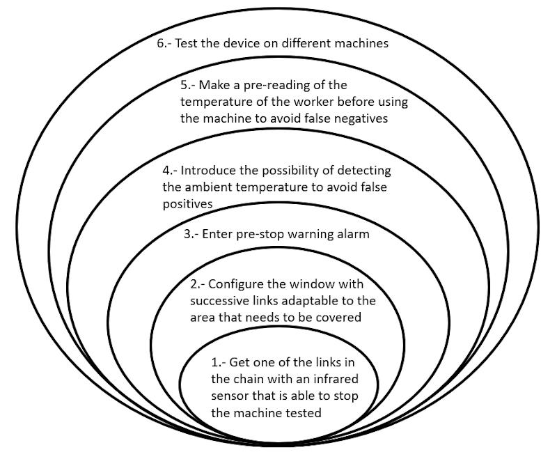
Doing a check:
-
Objective 1: Tests with a sensor on a link in the chain. Satisfactory result. Achieved
-
Objective 2: Modular adaptation of the sensors in the form of a window covering the danger zone. Satisfactory result. Achieved
-
Objective 3: Human presence detection alarm prior to machine stop. Achieved
-
Objective 4: Integrate the possibility of detecting the ambient temperature to avoid false negatives. The sensors of each link that forms the window, are measuring the ambient temperature in real time while the device is on. Achieved *
-
Objective 5: Take a preliminary reading of the worker’s temperature before using the machine to avoid false negatives. The worker’s temperature is measured and performed correctly. Achieved *
-
Objective 6: Test the device on different machines. Try a Dremel and a sheet metal bender. Satisfactory result. Achieved
I have met the objectives of all levels of the spiral diagram I have even taken a step further , by taking advantage of all this development to create another device, based on the same technology, with a different purpose, to control accesses and detect possible cases of Covid-19, in people with an elevated temperature beyond normal, something that occurred to me during the period of confinement due to the state of alarm decreed by the government of my country in the initial stage of this pandemic in order to be able to stop the curve affected by it.
The tests with this access control device, my IR traffic light, allowed to verify its correct operation.
*As for spirals 4 and 5, although they achieved what was imposed on each spiral and the device, by means of the integrated infrared sensors, is capable of knowing the ambient temperature and the worker’s temperature, the programming of the device, it is not prepared to vary the value set for machine stop according to the value of these two measurements.
Therefore, false negatives are not ruled out. Programming is not exactly my strong point and in the presentation of my project I explained that this was pending for the future.
In all the tests of all the options sampled and tested, the device gave an alarm and stopped the machine in the presence of human beings, since the set point of the temperature range was imposed “manually” in the programming, based on the standard temperature the environment in the region where the machine is located and the characteristics of the workshop where it is located, in addition to considering the human temperature also within a range of values considered standard.
The tests were always successful and therefore I “trusted” that even though my programming was not optimal and the values of the setpoint range in which the machine should stop were not automatically changed, depending on the variables: room temperature and temperature from the worker, the device would work smoothly during my project presentation.
And when he had the time and could investigate how to modify the schedule, he would be able to automatically change the lower and upper limit values of the worker’s temperature to ensure and guarantee that there were no false negatives.
I was so sure based on all the experiences of testing the device, that it would not fail that I proposed myself in the presentation of my project, a live demo of the operation of my IRW.
What happened in live ?, at the end of this documentation is explained.
Anyway, life …
Now, I am going to tell in detail all this adventure
Steps in the development of my FP
1. Design of the components of my F.P.
1.1. 2D and 3D Modeling
I have developed the modeling of my final work in the assignment of Computer Aided Design, visit week 3 assignment for more information.
I have chosen SolidWorks for the 3D design.
First I have created an assembly with the components of a single link, here you can see how it would be.

To shape the link chain, I have assembled consecutive links, introducing wiring and elements like screws, nuts, washers from the Solidworks toolbox.
The result is what is shown in these images.


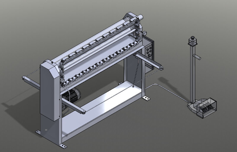
Finally, from SolidWorks I have made the assembly of my safety device (infrared window), incorporated into a machine tool.
The machine is a roller bending machine, in which entrapments can occur. There is a danger zone where the accident is most probably to occur causing entrapment damage.
The assembly of the chain with infrared sensors on the bending machine is as follows:
3D model can be viewed from sketchfab
These images show the detail of the possible connection of two links in series and in parallel.


1.2. 3D model animation
I have developed the 3D model animation in the assignment of Computer Aided Design, visit week 3 assignment for more information.
To fully define the model before the animation, I also used the Blender software.
For the animation, I have chosen 3DSMax software.
From the animation made in 3DSMax I have created this video:
Now I go one step further and add to the video a human hand stopping the machine when it goes through the window located in the danger zone of the machine.
Updates
Update 1
Once I have my electronic boards and I can try to assemble one on one of the links, I realize that I have to change the design of the link cap a little so that it is better adapted and that it does not rub against the connectors of the wires I2C.*
This is the new cap:

This is the link with the new cap:

Update 2
I have also had to develop a box to house the main electronic board, the two relays, the buzzer, the led, the cables and connections.
The box is shown in the following images:


It consists of a base and a lid.


Once 3D printed I hope it looks like this:

I will put this sticker:

2. Manufacturing processes in my F. P.
2.1. 3D printing of parts of the design of my final project
In the assignment of week 6, I updated the design of the base piece to form a chain of links.
That first link, together with a kind of cover so that what I want to put inside is better integrated, I have printed it in 3D and the result has been this:
I see that with this printer and this position of the piece the stagger between the printing layers is very appreciated, I will try to improve this.
To see how I would best assemble with other links placed in series or in parallel, I have printed another link and after thinking hr designed two pieces to put the chains in parallel and I have decided to put the links in series linked by a screw, which gives greater consistency than thermoplastic parts.


I have designed and printed two types of pieces to put the links in parallel at a greater or lesser distance.
In this way, a kit of parts can be made to mount the necessary sensors to configure the safety device to suit each circumstance.
This design evolved so that the sensor plates could be screwed on and guaranteed a good hold.
These are the new printed parts with the screw holes:

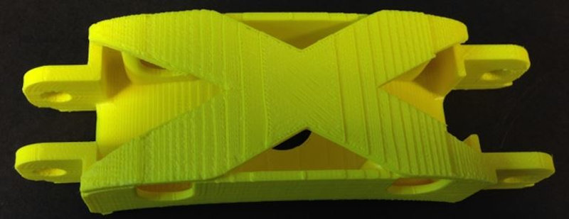
A new link cover design has also been 3D printed.
A yellow and a black cover are going to alternate, which are the colors of the safety beacons.

I have also 3D printed supports to attach the links to the wooden frame of the bender.

The printing of the box for the device control electronics, where I have put my board made by me, has been as follows:

Once assembled with its cover and sticker, this is how it looks:

2.2. Manufacture of parts with CNC milling machine
Wood pieces to cut on the CNC milling machine.
In the first instance, I set up the infrared window for a small desktop machine tool, specifically a Dremel. For this I only use 3D printed links with their sensors that I place in series, and the result is very good.
For the case in which the infrared window is implemented in a large format machine tool, as is the case with the roller bending machine where I want to put it, the same method could be followed, completing more links with more sensors.
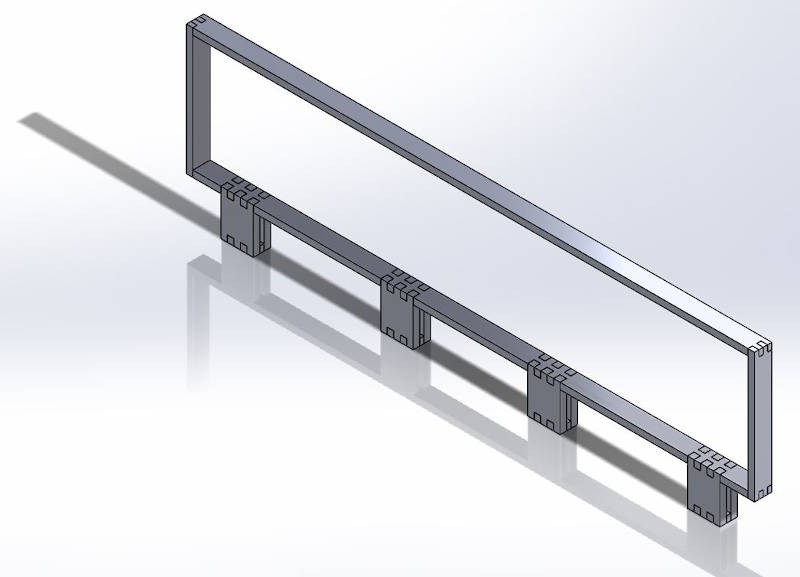
But, as an alternative, I have decided to create a frame design adapted to the bending machine, and then make it out of wood using the large format CNC milling machine. In this way I will also optimize the space and the arrangement in it of the sensors so that they cover the largest possible surface. Since I have a limited number of sensors to do this project.
This is my CAD frame design:
This would be the rack with the sensors:
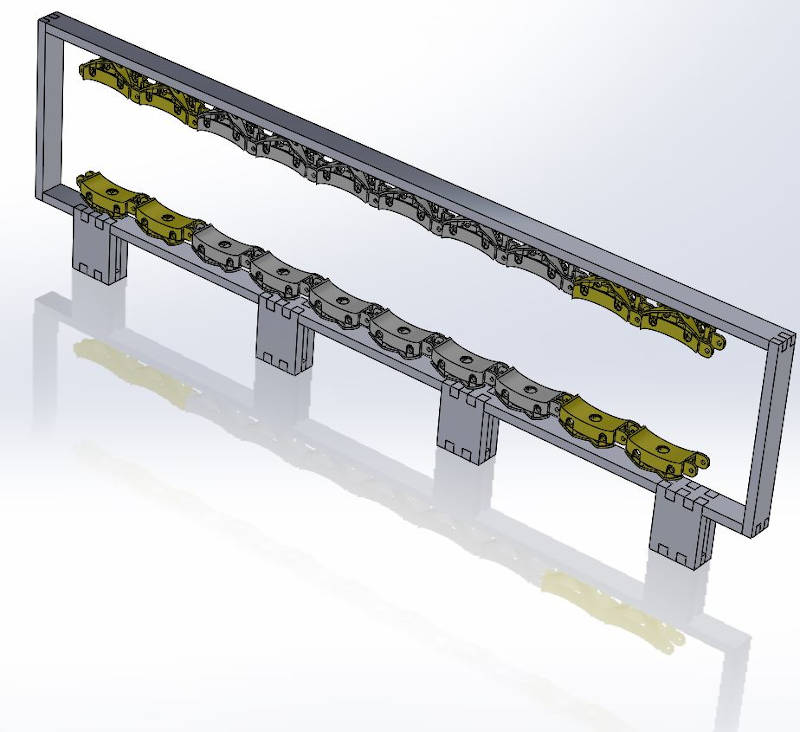
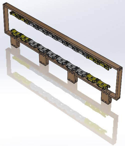
With textures it would look like this:
This is an animation of his assembly sequence:
I also thought about the application that occurred to me to give this infrared technology during the week of the applications and implications assignment, and decided to design the chassis of what would be the access control device with which you can control the temperature of the personnel that intends to access a shared space, in this way it will be possible to know if it presents this symptom and decide if access is allowed.
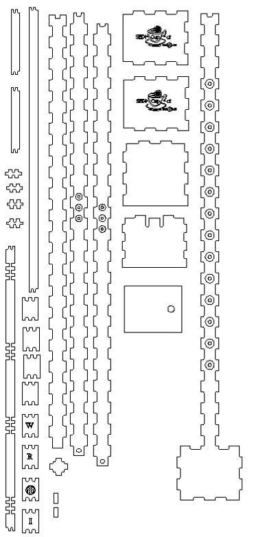
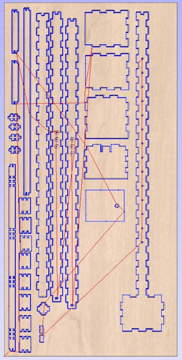
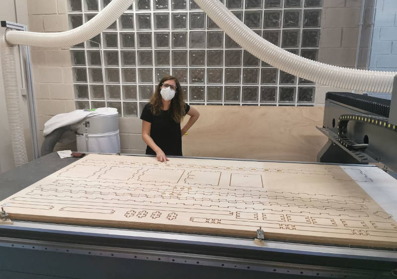
I created the manufacturing drawings of each piece in dxf of both designs that I imported from the milling machine software that is Aspire, and prepared the configuration to mill a 2.5m x 1.2m and 15mm thick, with the exploded view of both designs.
The result was this:
The result of the milling was this:
I separated the pieces of the wooden board and did the frame assembly:
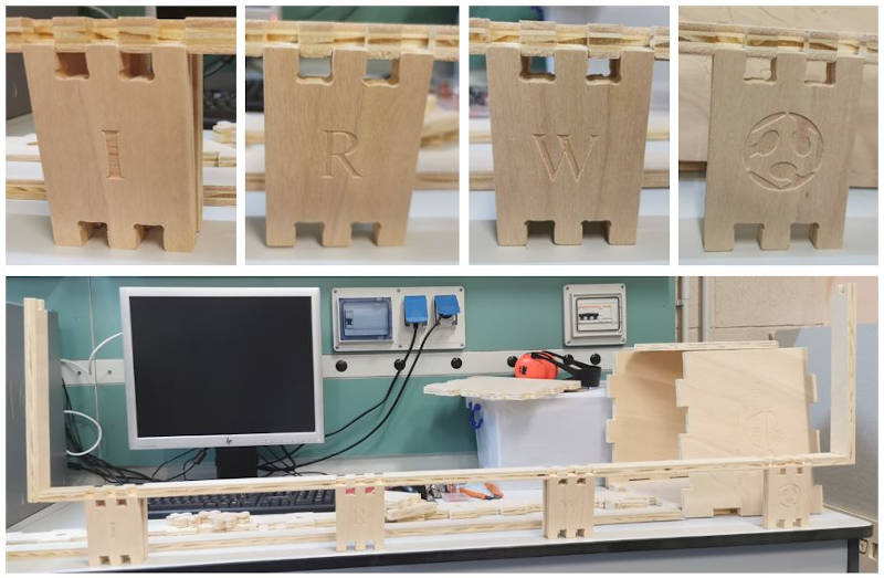
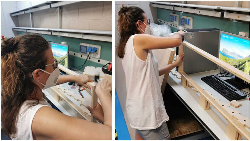
This is the frame mounted on the sheet metal roller bending machine.
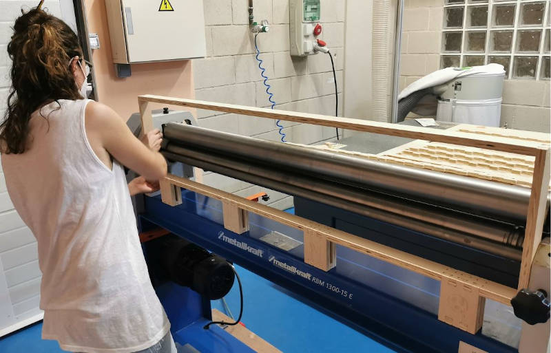
* I’m happy, it was perfect !!! *
3. Electronic development of my device
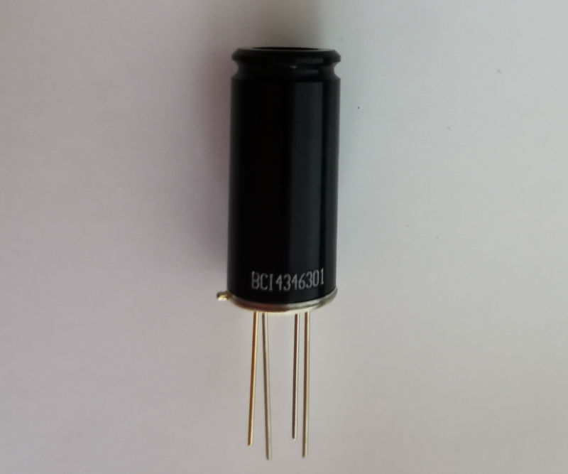
In the assignment of week 10, I have studied the infrared sensor to be used, and how it is integrated into the device.
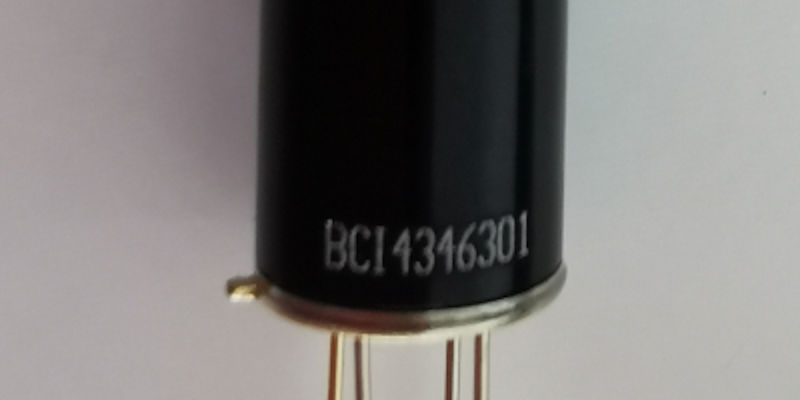
My infrared sensor is: MLX90614 BCI 4346301
I have designed an “Input board” that will be located in each link and will receive the signal from each infrared sensor, the boards will be connected in series and communicate through a I2C communication bus.
I have also designed a control box, where the main board will be located (more information in week12 ), in this all the output elements are configured.
The signals of all the sensors connected in series in the link chain will arrive at this main board and the order will be given to stop the machine to a relay that will cut off the machine’s power supply when an invasion of a human limb within the danger zone and this is detected by sensors.
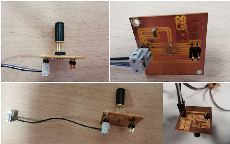
3.1. Input devices of “Infrared Window”
My sensor is this, with these pins:
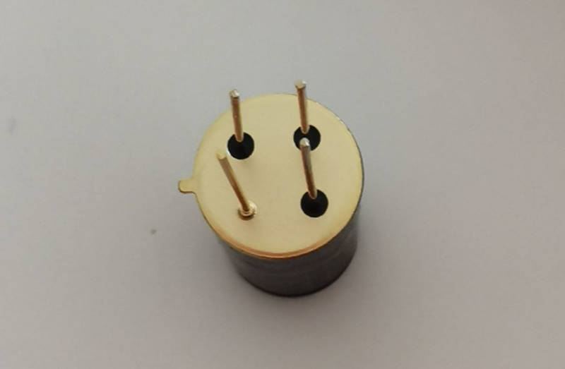
To connect it to the board, you will need a connector of this type:
(As I need quite a few, about 12 and I do not have enough without daring, the money from other devices that I have for the lab)
To have this component available from Eagle and be able to introduce it on the board that I have to design, I must first create it, since there is no similar one.
After creating it, I have modified the fab library, to which I have added the scheme and symbol of the MLX sensor to insert into the board design.
I configure the layout of the board connections and the result is this:
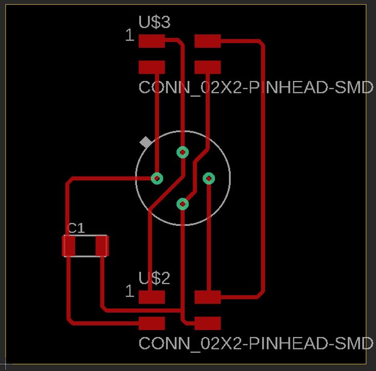
Then, I export the file as a png image to mill it, and it looks like this:
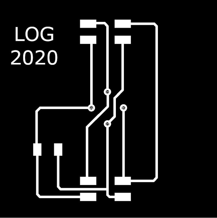
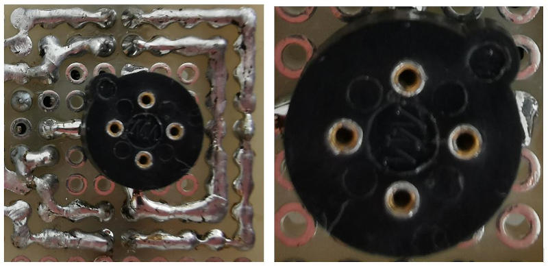
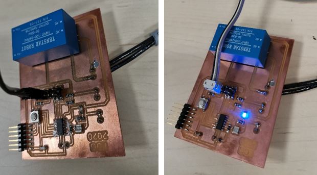
The milling of the board was as follows:

Next, the electronic components were tin soldered - 1 Capacitor C1 = 0.1 µF - 2 4-pin I2C connectors - 1 Round 4 Position Transistor Connector, TO-5 Gold Plug Through Hole

Using a Dremel, the holes for fixing the boards to the window links were made.

This same board has been replicated 12 times in order to form the links of the chain with the twelve sensors that I have available.
I2C connectors are used for the connection between MLX sensor boards. - Arduino cable - 2 4-pin I2C quick connectors

MLX sensor connects to the board:

The sensors connected in series by I2C cable and mounted on the manufactured plates, placed on the 3D printed links, look like this:

A cable gland is inserted into each link in the infrared window to house the MLX sensor.

3.2. Electronic control board of the safety device
Main programming board of “Infrared Window”
For this purpose, due to my inexperience, I initially designed this board that included an ATtiny44 microcontroller. (All information about this can be seen in the assignment of week 12)


A two-pole cable connects to the 230Vac power pin.

It is verified with the multimeter that there are 5 Vdc on the Vcc and Gnd pins

I connect the control board to the input board for testing.

To check its operation, I took a first step and loaded a basic program to light an LED on the digital output and verified that the board works correctly.
But the problem came when I had to test the programming that my board should be capable of executing, and this processor does not have that possibility.
Here comes my big problem!!
For my Final Project.
I need to program the reading of the sensors and their on-screen display in real time. The programming does not fit in the memory of this microprocessor. I have been testing.
So I decide to change it to an ATtiny84 for the final control board of the final project and I will also make the connector tracks wider, especially for the power cable and the different outputs, which is quite thick and loses the connection.
I decide this microprocessor because it has the same pinout, I check it on its datasheet.
But, another problem!!
I do not have this microcontroller in my Fablab and if I order it it would take a long time for its supply to arrive.
Well, I recover and look for another solution. So I have to try another microcontroller, this will mean making more changes on the board than I originally thought would have to be done with the change from ATtiny44 to ATtiny84, but it is what there is.
I test with the ATtiny 1614 and make changes to the connections. I test the schedule, and…
Still, I can’t get good communication with I2C, nor do I get the programming to work well.
Then, I try connecting my Input board and programming with Arduino and it works.

So finally, I decide that for my final project I am going to use the same microcontroller that carries the Arduino 1 board, with which communication and programming is somewhat more familiar to me.
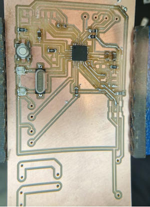
So I start to design my board from the SATSHAKIT board. I have followed the tutorial that is accessed at this link.
I will use the ATMega 328P microcontroller.
I check his DataSheet and his pin layout and start a new Eagle project.
This is the pinout of this microcontroller:

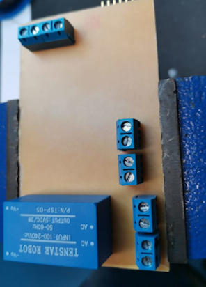
Another change that I am going to introduce in my new board is to have two outputs for 2 relays instead of just one. This is because I want my device to be able to act in two different scenarios in which:
- The machine where the device is located already has a manual emergency stop button.
- The machine on which the device is installed does not have an emergency stop and must act directly on its power supply.
This new Eagle project is called: LOGATMEGA.
The design process for this board in Eagle is shown in the following images:


Once designed including all the necessary electronic components, an image file is prepared to be able to mill the plate in the Stepcraft 420 microfresadors of our Fablab.

This is the plate prepared to be milled.

To manufacture it with the milling machine, I first configure this process with the Aspire software.


The result of the milling has been a little defective, the milling machine has suffered in this time, we have taken it from the lab to the house of my colleague Álvaro and now back to the lab and the change of place or tool has not been good for him since the other mill broke.
So it was difficult to calibrate it, level it and start it up again.
*I made a first milling attempt that was not valid, so in the plate design I enlarged the thickness of some tracks, and forgot to name the plate when preparing it for the new milling. *
Now, some tracks have gone bad and broken, I have tried to fix it by adding tin and bits of copper wire.
Finally the result of this arrangement after checking the conessions between tracks has been this:

After soldering the components, the board looks like this:
3.3. Electronics upgrade
3.3.1. New Input Board
In order to assemble the 3D printed parts with the sensors, sensor boards, cables, and all components, I must make sure that I will be able to make all the connections correctly.
By doing this, I see that I need a connector for the first link in my window and that the cables are well connected.
So I slightly modify the board design, mill it and mount the components, the result is this:

I test my newly completed electronic control board, connected to this input board with its infrared sensor, connected in series to other two boards with its sensors, so I can check if I have made it work the same way I got it to work with a board from Arduino.
This is the video of the test of the electronic control board designed, manufactured and tested to receive the signal from 3 infrared sensors (in this case) that measure the temperature. At the set temperature, an alarm will sound, a led will light up and a relay will stop the machine on which this device operates.
This works!! 😊
With the material I have, I have obtained 12 sensors and 11 connectors, so my “infrared window” security device will consist of 11 links 3D printed with one sensor in each with its electronic board communicated in series by I2C.
From here I have to work on programming and tests.
4. Test accessory. Artificial thermal hand
To test the IRW safely, and to verify that the sensors are correctly reading the temperature of the body and object entering its temperature measurement detection field, I have designed a test accessory.
It is an artificial thermal hand, I will replace it with mine, which I am quite fond of, to make preliminary tests of operation.
This element will be a mannequin prosthesis in the shape of a hand, similar to the one that can be seen in the following image:

A thermal silicone resistance is installed to this prosthesis that covers the entire hand and fingers.

And a thermal probe that sends the temperature signal.

I use a digital thermostat (I had it in the lab) with these characteristics:
Eliwell ID961I / On / Off Temperature Controller 12V-8A-PTC, 12 V ac / dc, -50 to +140 ° C

This is their connection diagram:

To set the temperature in the Eliwell digital thermostat it is done by adjusting the set and it is accessed by pressing and immediately releasing the “set” key. The abbreviations “SP” will appear. Press and release the “set” key again. Then, it is possible to modify the set value using the “Up” and “Down” keys; to confirm press “set” again. If the keyboard is not pressed for more than 15 seconds (maximum time) or if you press the “fnc” key once, the last value displayed on the display is confirmed and the previous display is returned.
SET access and use

I put a glove on my hand that has the function of uniformizing the temperature produced by the heating resistance, which makes this prosthesis much more similar to a human hand.

Finally, there is a 3D printed piece of fastening the prosthesis to a rigid PVC tube where the hand connection wiring goes to the thermostat. And my test accessory safely looks like this:

This is a check that my sensors read the correct temperature, since I know what temperature the artificial hand is marked by its thermostat. Furthermore, the device works by stopping the machine at the set temperature.
5. Programming and communications
I program the microcontroller ATMega 328P on my board with Arduino IDE. I indicate a response temperature of between 29 and 35º centigrade, * (I can vary this, manually, depending on the ambient temperature, the season of the year and the factors that may affect the temperature of a person, which is what we are trying to detect ) *.
When this temperature is detected in the field of vision of the sensors, there will be an audible alarm and an LED and two relays will act, one to interrupt the machine’s power supply directly and the other that will act on the machine’s emergency stop if it has it.
The programming is this:


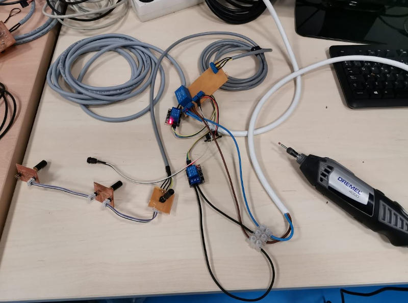
I test this programming on the device already assembled in the absence of finalizing parts and putting the board, relays and cables inside the box that I designed and is printing in 3D.

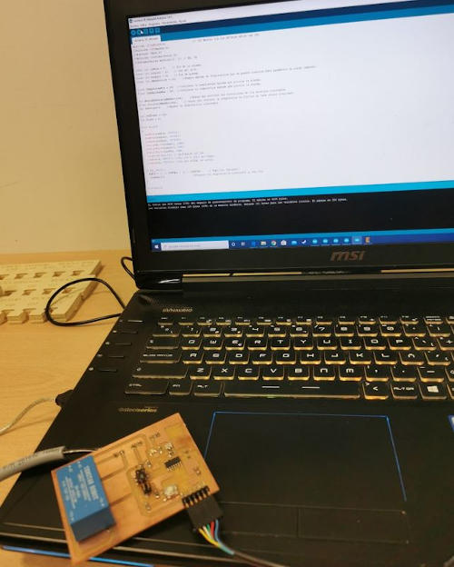
On the screen you can see the real-time reading of each of the 11 sensors mounted on the links of the window. And it is reflected every time the set temperature is reached so that the alarm goes off and the machine stops. (I’m doing all these tests with a Dremel at the moment).

Here you can see a video of these tests:
In order to have this data, I have connected an FTDI cable to my board, with which I have loaded the programming and I can see on the screen the temperature values measured by the different sensors.
But I have not connected the security device to the dremel to avoid damage to the FTDI cable.
* NOTE:* My colleague Álvaro had an unpleasant experience with this and more than one cable broke, so in addition to the loss of the cable, we had to find a supplier that had a quality cable (we bought two that were not working) and then pass a long wait for it to reach us. So I don’t want to risk running out of a cable like this again.
So after checking the programming in this way, I have also tested the safety device with the machine stop, in the case of the dremel that does not have an emergency stop, a relay operates that cuts off the power supply and stops the dremel when one hand gets too close to the moving tool.
In this new video I check that the relay performs its machine stop function, only when it is my hand that goes through the window, and that, if any other object or tool of different materials invades this screen formed by the sensors, the dremel continues working. This is just what I was looking for.
*Objective achieved!! * 😊
Now I have to mount all the control electronics in the box that is being printed in 3D and put the covers on the links that form the infrared window chain and this device will be finished.
Update:
After verifying that my board with the ATMEGA328P microcontroller works correctly with the programming created and is capable of processing the signal that comes from the sensors communicated in series through the I2C communication bus.
I make the assembly of all this electronics with its connections and put in the electronic control box that I have designed so that everything has its place and I already have 3D printed, all the components that have to be coupled to it, the board, the relays, the connections, the buzzer, the led …
This is the assembly process:
These are the components mounted in the box:

And this is the finished box, with its screwed lid and its identification label:

Once the box with all the electronic components is assembled, all the connections are made, all the window parts are placed, the sensors mounted on the links are correctly numbered and the programming is adjusted, this is the result of the IRW Safety device adapted to the Dremel.

The device cuts off power to the tool when a hand comes close.
Now, I want to test it with the roller bending machine.
6. Installing the infrared window on the sheet metal bending roller machine
Update
Roller bender test
According to my purpose, now I test the operation of the “Infrarred Window” for filly machine tool of greater size and that has a manual emergency stop device. (red manual emergency stop push button).

I connect the window with the current configuration, and the appropriate size for a small tool to the bending machine’s emergency stop system, and check that the device is capable of acting on the bending machine’s emergency stop and everything works.
Own connection of the machine to the manual emergency stop button.

The emergency stop of the bending machine I connect in series to the stop relay that I have on the main electronic control board.
*Serial connection of “Infrarred Window” safety device to the machine’s emergency stop button. *


In this way, the emergency stop is automated when a human member enters the danger zone.
After making the connections and provisionally positioning the window, without fixed fastening in front of the mobile rollers, I am going to do the proposed test.

In this video you can see the result of this test.
This is the satisfactory result of testing my safety device on a real roller bending machine available in the SEDICUPCT FABLAB machine shop.
*Another turn of the spiral achieved!! * 😊
Update
As I explained in section 2.2, I have created a wooden frame to mount the links with the sensors so that the area monitored by the sensors I have is as large as possible.

I use 3D printed connecting pieces to fasten the links to the wooden frame using screws.

I prepare the links to place in the frame asymmetrically between the top and the bottom of the window, and thus at a reading angle the sensors will cover the largest possible surface. Putting them alternately there will always be a sensor covering the area.

The result of this placement is this:

To test my IRW window on the bender I am going to use my artificial hand first.
I wait for my hand to reach the temperature of the human body before testing the operation of the IRW device.

I do the machine stop test, using the artificial thermal hand, acting on the bending machine emergency stop.
The relay of my electronic system activates the emergency stop of the bending machine when the artificial hand invades the established area with my safety device.
Finally, I am going to test the machine stop by doing a workshop task.
I’m going to run a sheet metal through the rollers of the bender.
And in that task, my hand is going to get very close to the rollers. See what happens?
I am left in doubt if my hand stays under the sheet metal, the machine would stop. So I do that check.
Everything works correctly.
I am very happy with the result!!!
The sun finally rises ☀️
7. Infrared Traffic Lights
To curl the curl, I want to test this device for another purpose. The access control.
I am going to test putting it in a vertical structure next to the frame of an access door to a room, and it will measure the temperature of the people who try to access it. It will give alarm when the person who is entering has a higher temperature than what is considered normal.
This can be very useful in a situation like the current one with the COVID19 pandemic.
Maybe we will put it into practice in our FABLAB.
Update
It seems incredible to me to have reached this point and now to be solving this other approach. It is a job that is even out of the spirals of my initial final project proposal.
Given the special circumstances of this 2020, I am proud to have achieved the goals and go one step further.
In point 2.2 of this section of my repository, some image of the milling of the pieces that I have designed to make this new development already appears.
The design is this:
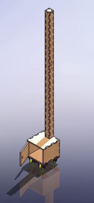
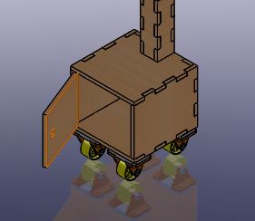
It is a portable wooden structure that has the electronics developed for the sensors of the IRW security device integrated, but now the purpose is to measure the temperature of the people who try to access a place where they will share space with other people.
In the lower cabinet that has wheels to facilitate its portability, will be the electronic control components.
The electronics is a replica of the one created for the IRW sfety device.
In the mast, the sensors go to different heights, so that it can be used for people of different stature.
And also a green led that gives entry permission, and a buzzer and a red led that warn of the alert of possible illness in the person who wants to access, since their temperature is higher than normal.
All parts have been manufactured on the CNC milling machine and have been assembled in the following order:
That’s how entertaining I’ve been…

Here are the two LEDs the buzzer and the IR sensors.

This is how my infrared traffic light looks. (TL-IRW).

And this is how it works:
It would only be necessary to change the temperature setpoint in the programming for the intended purpose.
We are going to start using it in the FABLAB, right now!!!
UPDATE after the presentation of my FP on July 1, 2020
Everything was happiness, even with the nerves of speaking English and presenting a work that has taken me months in just two minutes. But despite these two compelling reasons, I was confident in myself and that everything was going to be fine since the results of my project had been very good in all the tests, and at no time had my device failed.
100% of the tests had stopped the machine at the critical moment to avoid entrapment or damage to the limb that invaded the danger zone.
So, I was prepared, I had tried the device over and over again.
And the moment arrived…, while waiting for my presentation turn, my state of nervousness began to grow, creating anxiety.
All this is something that still surprises me, because I am used to speaking in public and teaching, activities that require a certain degree of exposure of knowledge and the ability to transmit it, and I face these situations on a normal basis, but I am Of course, between the Covid, my state of health, the stress of finishing the final project in record time, entering the FABLAB after hours due to restricted access control, the family and professional demand emphasized by the situation, caused the tension build up, and I felt like a pressure cooker.
So, the presentation was so-so, I got a bit stumped trying to speak very fast in English to give me time to say everything I wanted to say about my project and then I started to get even more nervous, and I don’t know if I I understood some of how fast and hasty she spoke, also with the disadvantage that I wear braces and it is difficult for me to pronounce. Total, nonsense.
This was added to the fact that on July 1 in the area where I work it is already very hot and this year is being especially hot, in addition, as the FABLAB was partially closed and for reasons of COVID-19 all the ducts of air conditioning in which air is exchanged, this was out of order, we did not have air conditioning.
All this made my body temperature rise abnormally and sweat profusely. The ambient temperature also rose due to having the machines and computers turned on for a long time and also due to the latent heat, my colleague Álvaro who accompanied me in the workshop and had to expose his work after me, was not very calm either.
So what shouldn’t have happened happened, and when I did the live demo that I had given myself in order to improve the not very bright presentation that I had tried to expose, my temperature and the environment were through the roof, and exceeded the maximum limit entered manually in the programming of the device, which made that when doing the test, the device did not trigger the stop of the machine and I almost died of frustration.
This is how my presentation ended, evidencing the importance of this, the last step to be taken, which I had taken into account and planned as future work.
This is what I said in the presentation of my Final Project, synthesized as much as I could and still, it was a bit long for the little time I had:


For me it was a bitter end. It took me a while to get over my frustration.
A lot of work and I consider it very good, behind a bad moment of NO success.
With all this, I think the questions posed as a task in this section of Fabacademy are answered, the questions are:
What task has been completed and what task remains?
Spiral diagram, all levels achieved and project development steps completed and documented, satisfactory results.
What has worked that has not?
Everything developed works.
What question needs to be answered?
What has not yet been developed and was proposed as a future improvement. This is the programming so that the temperature setpoint is calculated automatically from two variables: the worker’s temperature and the ambient temperature.
It is also necessary to provide for the creation of a device specification sheet, an instruction document and a maintenance protocol for the device.
What will happen when?
When there is a risk of entrapment or injury to the worker due to invasion of the danger zone, the machine stops working.
What have you learned?
In carrying out this project I have learned a lot about the different techniques used. Especially in electronics and programming, I have also had the opportunity to find different applications for CNC machines and miniature milling machines. It has been a very intense job and it has opened up new horizons for me. My goal was a bit ambitious and it would have taken a little longer to include the automatic temperature setpoint in the programming.
The biggest lesson “Take the time that each thing requires” and “Do not leave for tomorrow what you can do today”
8. Downloadable files of my final project
CAD and .stl files:
Module to support the IR sensor
Electronics Control Box
-
Electronics Control Box Base design (sldprt / Solidworks part file)
-
Electronics Control Box Top design (sldprt / Solidworks part file)
-
Electronics Control Box assembly design (sldprt / Solidworks assembly file)
Wooden structures made in CNC:
Wood Frame
Infrared traffic light wooden structure
Electronic elements:
Sensor MLX Board
- EAGLE file:
Sensor MLX Board EAGLE_project
- Board PNG files:
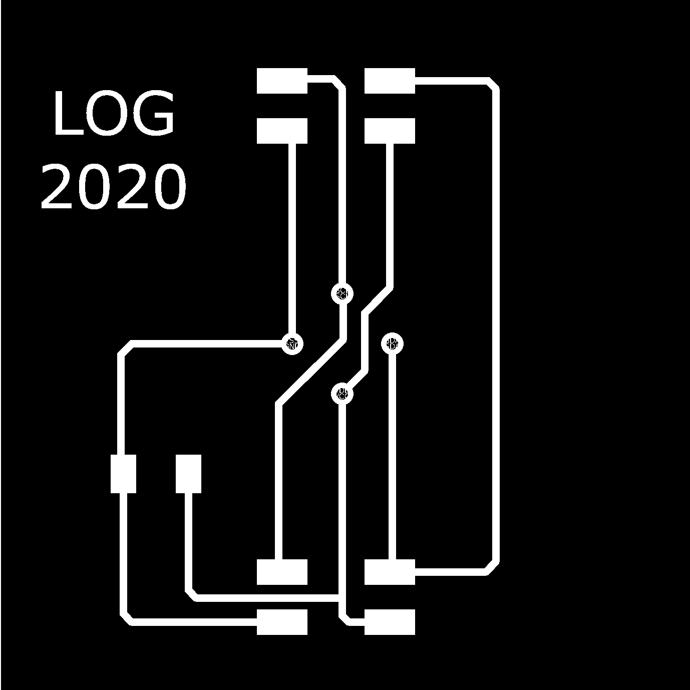
Sensor MLX One Board
- EAGLE file:
Sensor MLX One Board EAGLE_project
- Board PNG files:
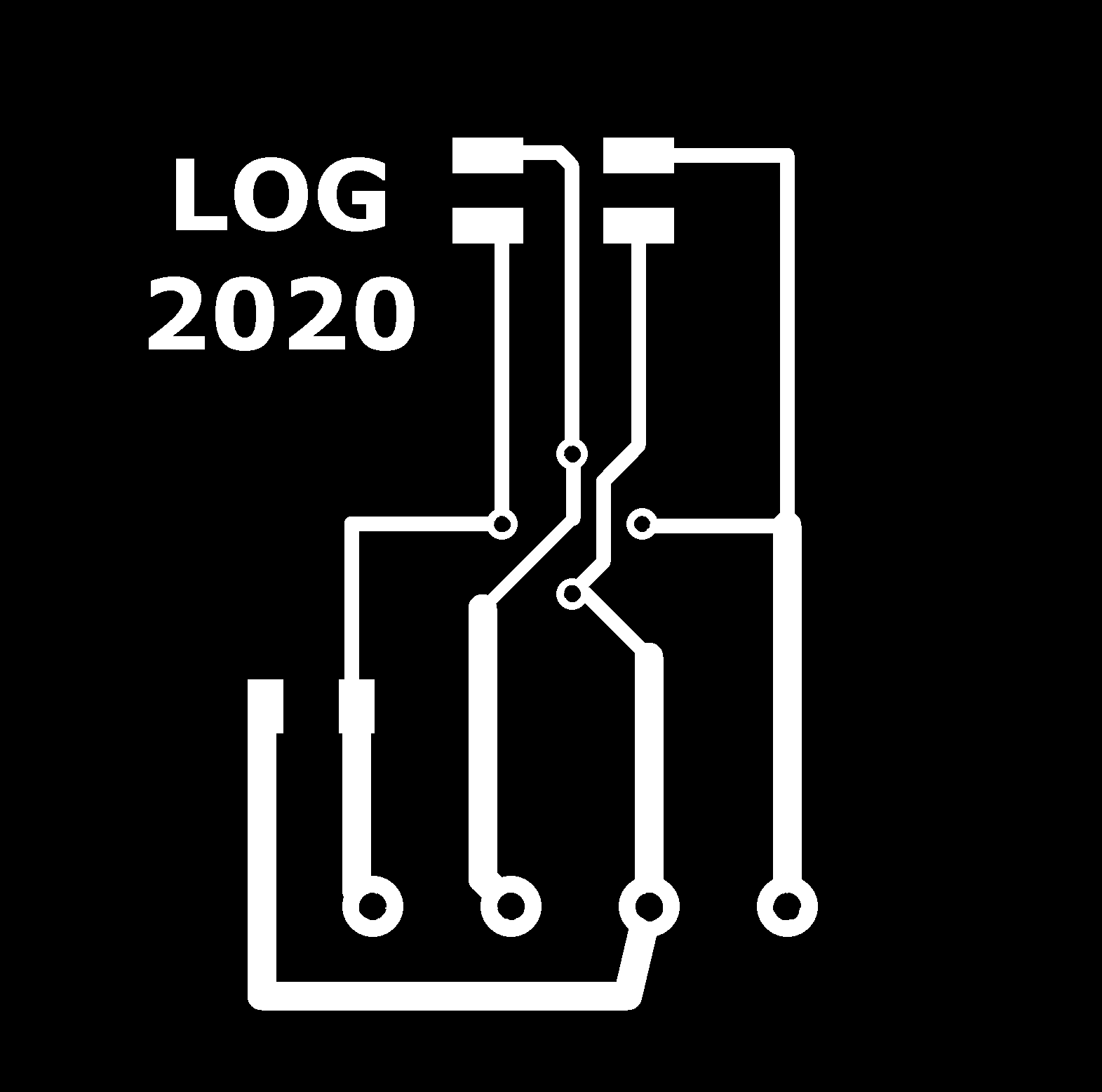
LOG-ATMEGA-328 Control board
- EAGLE file:
- Board PNG files: