11. APPLICATIONS AND IMPLICATIONS
This week I worked on Week 11 assignment:
It has been an individual work in which I have had to answer all these questions about my final project.
Statement
Propose a final project masterpiece that integrates the range of units covered, answering:
- What will it do? ✔
- Who’s done what beforehand? ✔
- What will you design? ✔
- What materials and components will be used? ✔
- Where will come from? ✔
- How much will they cost? ✔
- What parts and systems will be made? ✔
- What processes will be used? ✔
- What questions need to be answered? ✔
- How will it be evaluated? ✔
Aspects to consider
Your project should incorporate 2D and 3D design, additive and subtractive fabrication processes, electronics design and production, embedded microcontroller interfacing and programming, system integration and packaging.
Where possible, you should make rather than buy the parts of your project.
Projects can be separate or joint, but need to show individual mastery of the skills, and be independently operable.
I have continued using my weekly planning in which I have updated my activity in FabAcademy
As for the personal,
This is the week of the Easter Break, we are still confined, I am still on medical leave for my health problems and I am still not feeling very well, I have not fully recovered and I do not disconnect from work and the problems that are arising of the coronavirus pandemic and the implementation of alternative work plans in these circumstances.
My little daughter has gastrointeritis and my father has a cold and arrhythmia, he has a heart condition and this is another concern, and I am also worried about my little sister who is almost seven months pregnant and having problems.
*In short, it is not being easy at all.** *
“I can’t completely focus on anything while I’m everywhere.”
Also, I have had problems updating my documentation in the repository.
Regarding FabAcademy,
I have tried to solve the problems that arose from having incorporated a lot of information locally and when trying to upload it to my repository and exceed 10 MB, it was impossible, git was blocked, I had to clone the repository and try to upload my progress little by little without exceed 10MB in each git push. (I have told you this in an update to the documentation of the assignment of week 2, in which I learned to use GIT).
When this seemed to be working and I was able to update quite a bit, but not quite my progress, another problem has started to appear.
At the end of this week’s assignment information I have outlined the problems with Gitlab and how I solved them.
FINAL PROJECT MASTERPIECE
11.1. What will it do?
The started objective of my final project is to develop a sefety device adaptable to tool machines existing in mechanical workshops.
To achieve this main objective, the application of infrared technology for the development of safety devices in machines is proposed, based on the design of an infrared sensor window that can be manufactured and serves as a prototype.
The next phase will consist of the subsequent execution of functional tests of this prototype that detect, in the unsafe area, the presence of foreign bodies, discerning whether or not they correspond to parts of the human body and, if they are, perform functions automatic alarm (led and buzzer) and immediate stop of the machine.
An unsafe area is understood to be that of any machine in which moving parts are found that involve mechanical risks if they come into contact with the worker, which should therefore not be accessed by any part of their body, but where they should nevertheless normally be present raw materials, materials or products with which to work.
As a field of application for this device, all types of machines and tools operated by a power source other than human are considered as long as they incorporate a mobile tool, for example: bits, saws, etc., that generate a mechanical risk when the operator it introduces a part of its body in the dangerous work zone of the machine.
The device must act remotely, at a certain distance and without interfering in the normal development of the work process on the machine. Additionally, it will recognize the bodies introduced in the unsafe area, distinguishing the human limbs from the rest of the elements, thus avoiding the machine stopping when said area is crossed by materials or products that should be there during the normal work process.
The reason why infrared sensors have been chosen is the implementation of the variable “temperature” of the human body, this being a very characteristic parameter and that it usually suffers very small variations (between 36-37ºC) and that it is usually different from the temperature of objects in the environment.
This leads us to believe that a technology capable of measuring temperature, such as infrared technology, and that they can do so without coming into contact with the object, can satisfy all the required requirements and correctly fulfill the assigned function.
OPERATION EXAMPLE
In this video created in the assignment of week 3 you can see the operation of the designed infrared sensor window, acting as a safety device, and placed in a roller bending machine.
When the operator’s hand crosses the unsafe zone, the machine stops and hand trapping on the rollers is avoided.
11.2. Who’s done what beforehand?
At the moment I have not found in Fabacademy any work that relates thermography with the implementation of security in machine tools.
In fact, I have not found any external references of works similar to what I want to do either.
What I have found is a lot of information on the applications of infrared thermography to the inspection and maintenance of industrial machinery, but, in the scope of this technique as a safety device on industrial machines, I can only refer to previous work carried out from my own research group.
In this area, the first job in which thermography applied to machine safety was used, was carried out within New Safety Devices in Machines (NDSM) research group, and was an End-of-Master Project (TFM, in Spanish) by a student of the interuniversity master’s degree in Occupational Risk Prevention (PRL, in Spanish) between the University of Murcia (UMU) and the Technical University of Cartagena (UPCT), which was led by two colleagues from my research group and mentored by me, since the assembly and testing were took place at the Central Research Support Service (SEDIC) facilities that I coordinate and where the FABLAB of the UPCT is currently integrated.
This is its title:
NEW SAFETY DEVICES ON MACHINES USING THERMOGRAPHIC CAMERAS
This is the person who performed it:
Student: Juan Antonio Raja Valverde
And, this is the link where you can access this work done in 2013.
This was the machine tested:
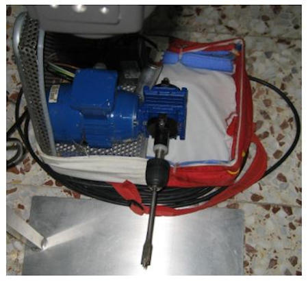
And this was the camera used in the test:
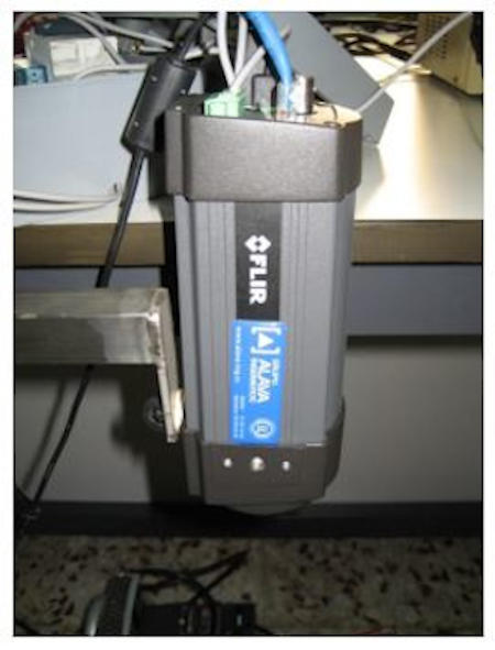
Given the results obtained, which met the stated objectives of controlling the automatic stop of a rotary machine, I continued with this line of research from the NDSM group, assembling a measurement system using a thermographic camera attached to the bending machine rollers seen in the image.

This other image summarizes the project:
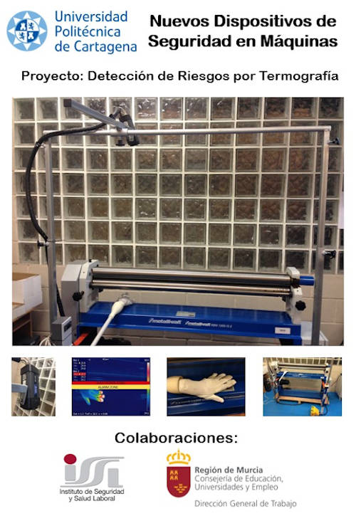
That gave rise to a communication at the ORP Zaragoza 2014 international congress dedicated to the Prevention of Occupational Risks which can be accessed from this link.
From here, it was possible to verify the efficiency of this technique, thermography, in order to be able to adapt it to machine tools and improve safety in its use.
The problem is that a thermal imager is expensive equipment, sometimes more than the machine to be inspected and to adapt the security system and, on the other hand, it is versatile equipment that can be used for many other uses, and its Incorporation in a single machine (even if it was economically profitable) would greatly limit its field of application, for example, we at SEDIC have two complementary chambers, used by researchers and professors for their research and teaching projects. If we condemn one of them to this use, we leave without being able to give service and without being able to carry out many other studies and works.
Furthermore, this would be unfeasible in a workshop where there are multiple machine tools liable of implanting a safety device.
11.3. What will you design?
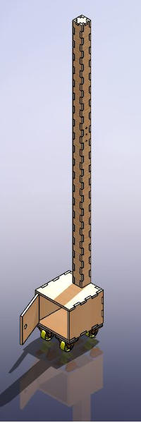
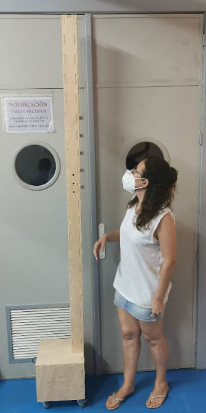
For the configuration of the safety device that is intended to be manufactured, a succession of parts must be designed in which the infrared sensors that emit temperature measurement signals to be monitored can be mounted. It will be like a chain of links where the infrared sensors are located and that can be modulated and adapted to machines of different kinds whose danger zone (or unsafe area) has a variable area, adjusting at home to the necessary size.
It is necessary to design the electronics capable of making the device work and carry out the programming of the software in addition to defining the communication system used.
There will be a control system, the inputs will be the measurements of the sensors and the outputs an alarm with led and buzzer in the first instance and immediately after the machine stops.
Mechanical design
For the links, a two-component modular part has been designed: sensor holder and cover.
This is the CAD design of the window links:
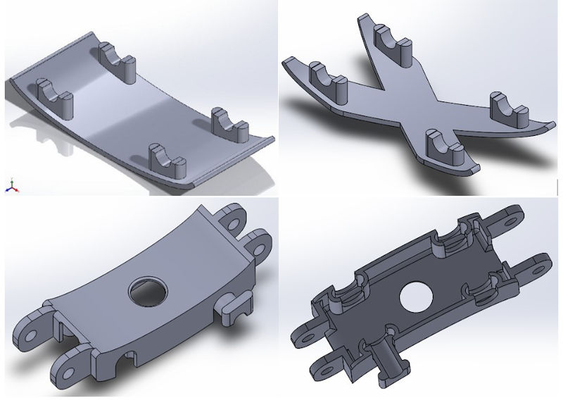
The parts will be 3D printed and can be placed in series and in parallel with adaptation parts of different sizes also designed in CAD and obtained by additive manufacturing.
More information in week 3 assignment.
Electronic design
The work sequence will begin with mounting a single sensor on a link in the chain that forms the window.
When the operation of this first part has been verified, the device will have more active sensors with which it will be attempted to cover the area considered to be a dangerous area of the machine.
These sensors will work under the guidelines of the integrated circuit in an electronic box.
This is the circuit that will be designed and will have integrated the program for the operation with the sensors and the activation of a led and buzzer as an alarm when the consigned conditions are met and later machine stop, acting on the power supply or on the machine’s own stop device, if it has one.
Image of the circuit designed in the assignments of week 10 and week 12:
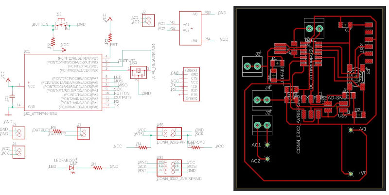
The programming and control of the electronic circuit will be done with Arduino. I2C (4-wire) communication will be used between the sensors and the Arduino.
Each sensor will have a memory address to name it during programming.
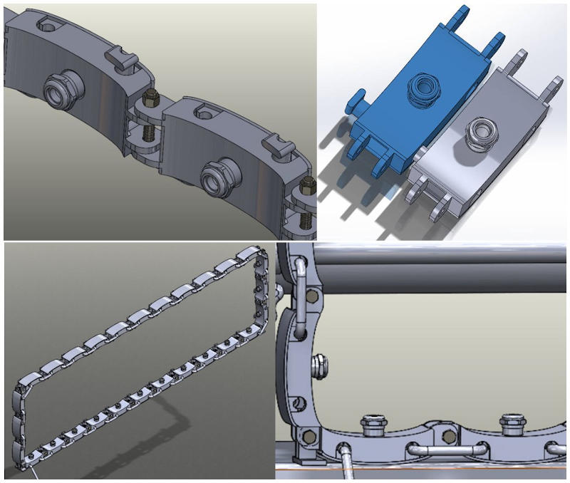
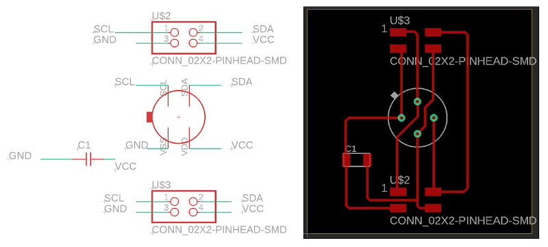
To meet the targeted functionality and modularity, a small circuit will be added for each link in the sensor chain.
This circuit contains a connector for the sensor, which facilitates its assembly and disassembly, and two connectors where the wiring between the links will go.
In the complete design, all the mechanical parts (links and clamping system) and electronic parts (infrared sensors with their circuit, wiring, control box) of the infrared sensor window system that will be the safety device will be assembled.
Programming will be done so that when the device is turned on it automatically identifies the number of connected sensors and their I2C addresses.
This will make it easier to change the window size and number of sensors settings without having to modify the program.
11.4. What materials and components will be used? Where will come from? How much will they cost?
For the manufacture of the support and the sensor cap of each link, the additive manufacturing technique will be applied and PLA or ABS filament will be used, depending on the FABLAB machine in which it is decided to 3D print these parts.

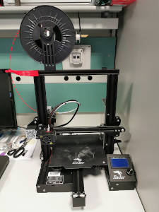
This filament is available from the FABLAB and is purchased through the usual local distributors. The amount used will be 1 kg approximately of material.
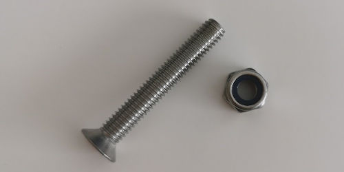
Screws, washers, and nuts will be required to join one link to another. This material is available in the mechanical workshop part of the SEDI-Cup-ct FABLAB.
As for the electronic material, I have identified all this material necessary to be able to manufacture the proposed security device.
Most of the components I have bought from Amazon due to deadlines and are on the way.
I have bought an Arduino starter kit that contains several of the components that I am going to use and in some of the cases I have bought a pack of several components for any problem that may happen and for economy.
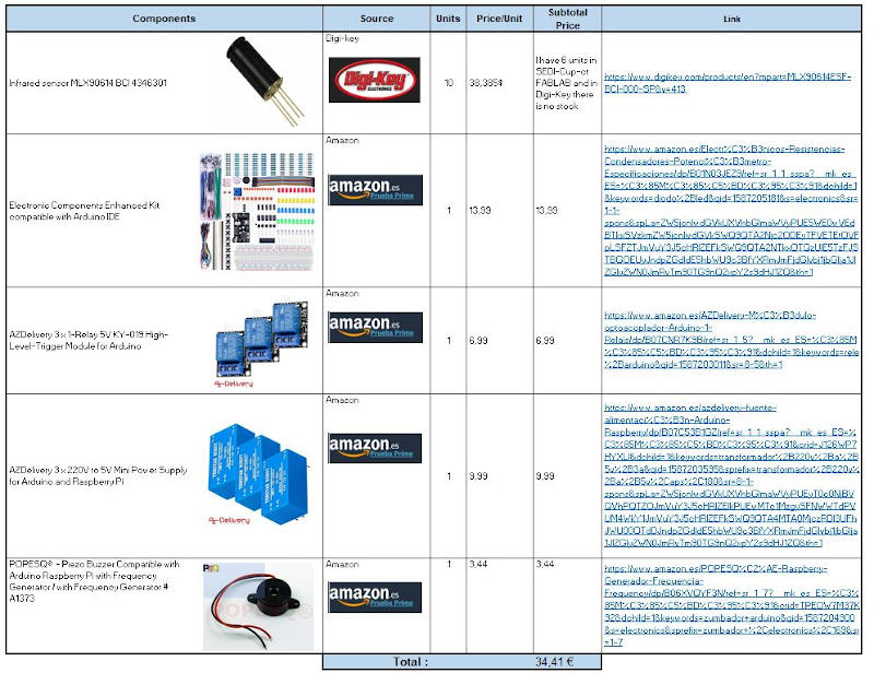
All this apart from the electronic material that I already had in the Fablab, the ATtiny44 microprocessor, resistors, capacitors, connectors, …
11.5. What parts and systems will be made? What processes will be used?
I will use 3D printing, hardware and if necessary mechanical machining for the link chain part of the window.
I will make the printed circuit boards and the assembly of the control box and the boardss of each of the links.
If necessary, I will make a laser cut of some material that allows me to make the parts that act as accessories.
11.6. What questions need to be answered?
In the next few weeks I hope to learn more.
I want to check that the boards configured as input and output devices work. See how I assemble and solve the operation of my final project with the stated objective. I’m also concerned about the sensor reading, and I wonder:
-
How to use the I2C communication protocol? I think that in the assignment of “networks and communications” I will learn it.
-
Will my sensors work well? Will I be able to get a good temperature reading?
-
Will I be able to test my device safely? I think I will find a way to minimize the risks.
-
Will the components chosen be suitable? I especially wonder about the topic of the transformer.
-
Will my alarms work well and will the emergency stop signal be received correctly? Will this stop execute correctly?
I will have to try it.
I will think it through very well and I will solve problems as I go along.
11.7. How will it be evaluated?
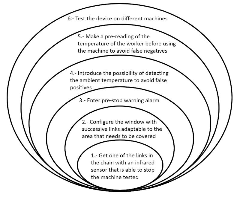
I have structured my final project by posing a series of objectives, from an initial objective, easier to achieve, including development phases, to reaching a security device that can be tested on different machine tools, I do not know if I can achieve it with the resources and the time I have, but everything will work.
All this is collected in a spiral diagram.
Each step in the spiral can be evaluated.
UPDATE:
During the completion of this FabAcademy 2020 training, after choosing my final project, many things have happened that have turned the world upside down.
As I finish developing in my final project, what occurs to me that it may be useful using the device for detecting human presence through temperature that I have designed as a security device that I have named IRW (Infra-Red Window), is give it an app like “Access Control” .
In reality, this idea was born with the reality that we have to live in these moments in which we are in the middle of the COVID-19 pandemic.
It occurs to me that my device can be used to control the access of people avoiding those who present any symptoms of fever without having to use thermometers.
That is why I have developed the Infrared Traffic Lights from IRW which can be seen below:
I think that by polishing the programming a bit and communicating the reading of the device with the opening of an access door. The passage of healthy people to rooms could be automated, limiting access to people with symptoms of fever.
There I have presented my idea !!