8. COMPUTER-CONTROLLED MACHINING
This week’s assignment is to carry out a project of a large format design that can be built with our FABLAB CNC milling machine.
First, as a group work, my colleague Álvaro and I are going to characterize the parameters of our machine, which is also recently acquired. This work will help us to deepen our knowledge of the machine and optimize the milling processes that we are going to carry out with it now and in the future.This week I worked on defining my final project idea and started to getting used to the documentation process.
The statement of both group and individual assignment is:
-
Group assignment
- Test runout, alignment, speeds, feeds, and toolpaths for your machine.
-
Individual assignment
- Make (design+mill+assemble) something big.
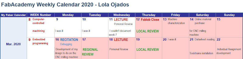
As usual, I have recorded what I have developed this week for the realization of this assignment, in my FabAcademy calendar.
This week has been critical and there has been a turning point in our daily routine, in general and in my entire life in particular.
This week in Spain, just the day after the FabAcademy Lecture, on March 12, 2020, a state of alarm was declared due to the worldwide pandemic of COVID-19.
This special situation affects the scope of work, domestic infrastructure, family organization, school planning, in short, something very difficult to face without losing your mind a little.
As for the personal, in my case, I have had to be operated on urgently for a health problem that I have been dragging since the last quarter of 2019 and has worsened.
With what my life has been complicated a lot. I am on medical leave, teleworking and trying to make my commitment to FabAcademy.
Before and during the beginning of this chaos, I have managed to go under exceptional authorization to enter the Fablab, to prepare equipment and finish urgent tasks, to carry out the Group Assignment together with my colleague Álvaro. And after that, make the online purchase (since the physical stores remain closed) of the necessary material to be able to carry out this assignment when it is possible to enter the lab again.
At the moment I am not in very good health either and I have to give space to recover.
I attest that it is a bad time for anything, but above all, to get sick of anything …
8.1. GROUP ASSIGNMENT
This is the link to access the space of group assignment from FABLAB León.
This group assignment has been done by my colleague Álvaro and me with the CNC milling machine that we have at our FABLAB in Cartagena SEDI-CUp-ct Fablab (link).
Our milling machine is the SW1325 de CNC Barcenas.
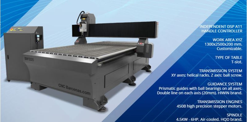
Other features:
-
Maximum speed:
-In air: 20 meters / min.
-At work: 15 meters / min.
-
Resolution +/- 0.05 mm.
-
Electromandrino
Brushless high frequency motor with air-cooled ceramic bearings. Power 4.5 KW. - 6 CV. · ER32 milling cutters from 1 to 20 mm. From 4,500 to 18,000 rpm. with adjustable speed from the machine. Capable of reaching 18,000 rpm. and perform great works of cutting, carving, 3D reliefs on wood, plastics, resins, foams and a multitude of materials.
8.1.1. Aspire software
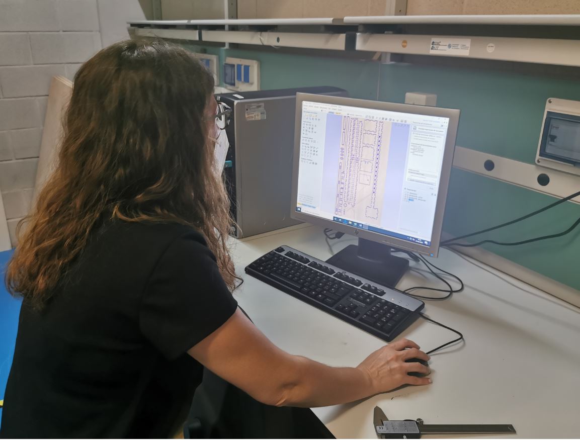
To generate the G-Code we use Aspire software. We design a part for the feed rate test. These steps will be general for all milling we do.
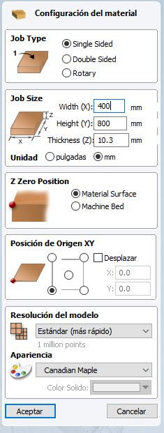
- We set the dimensions of the work material and the reference point for the Z Zero.
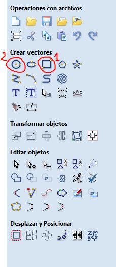
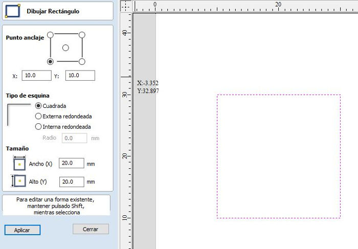
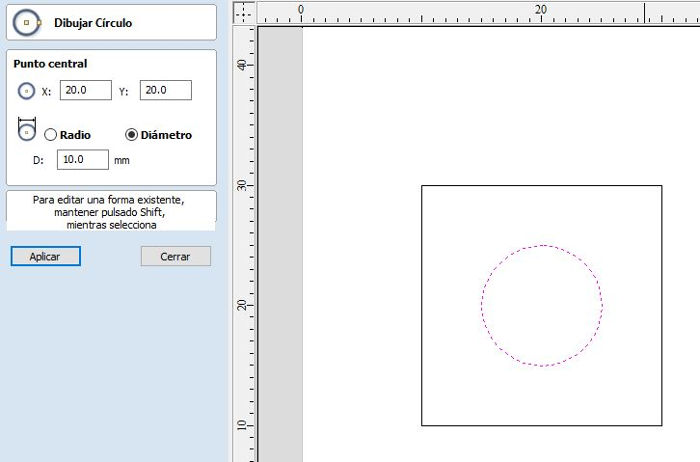
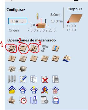
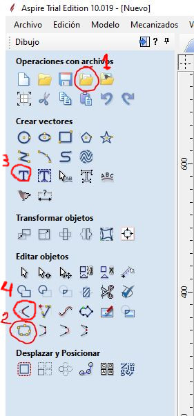
- We use the tools to create vectors to draw the piece (1)(2). We will draw a square, whose perimeter we will mill with a depth equal to the thickness, with a circle inside whose surface we will mill 1.5mm deep.
-
Selecting each vector (rectangle and circle) we configure the type of operation we want to perform. Basically, we will use 3 types of operation:
-
1 Profiling operation. We use this operation to mill the vectors perimeter. Useful for cutting outlines.
-
2 Pocketing operation. We use this operation to mill the inner surface of a closed vector. Useful for engravings y joints.
-
3 Drill operation.
-
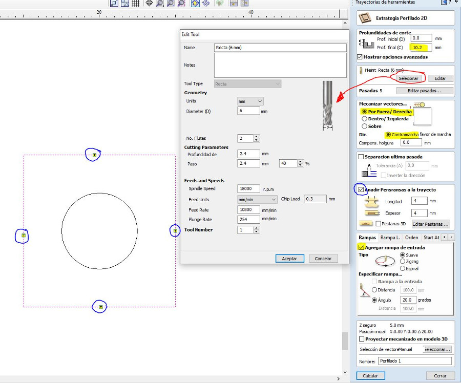
- For the rectangle we use a profiling operation. We set the cutting depth equal to the thickness of the material (or slightly higher to make sure we cut the bottom surface). We select the tool. We select the type of machining of the vectors “Outside / Right” and “Countermarch”. Add Penransas so that the piece is fixed throughout the milling.
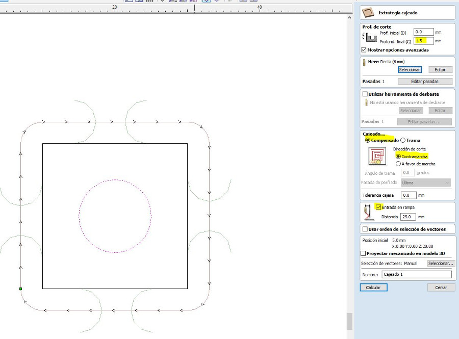
- For the circle we use a pocketing operation . We set the depth of cut equal to the thickness 1.5mm We select the tool .
- We can see a simulation of milling operations to check that everything is correct.
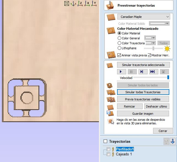
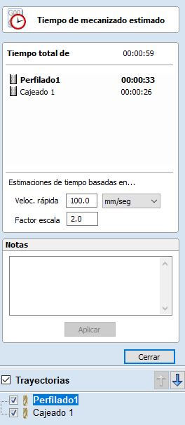
-Next we can see an estimate of the time that each operation will spend.
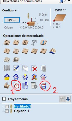
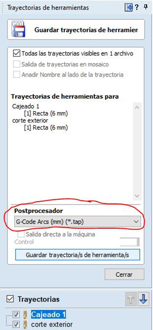
- Finally we save the G-Code file on the pendrive. For our machine we have to select the Postprocessor “G-Code Arc (mm) (* .tap)”
8.1.2. Operating the milling machine
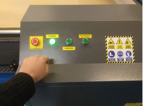
- Turn on the router.
-
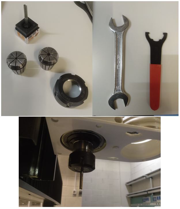
Insert the pendrive in the DSP with the files in Postprocessor format “G-Code Arcs (mm) ( .tap)” or “ISO plain G-codes-mm ( .iso) for the 4th axis”.
-
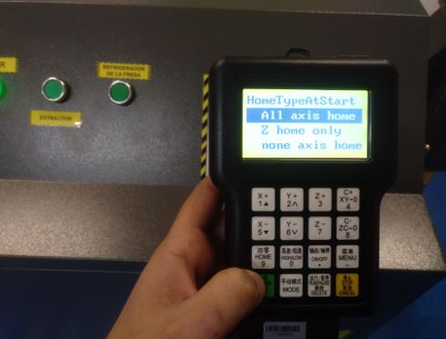
Do HOME. The DSP will display: HomeTypeAtStart.
3.1. Press axis home and OK key. The machine will be positioned at its starting point. The X axis to the left, the Y axis to the top of the table and the Z axis above. 3.2 The machine is now ready to work. This step is essential for the proper functioning of the machine. ALWAYS have to do HOME.
-
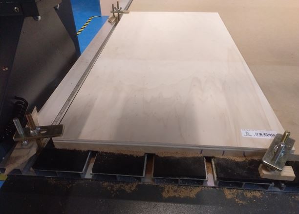
We place the workpiece and hold with grips.
-
We position the machine in the XY0 point previously marked in the software, generally the lower left point is used. 5.1 Once the milling cutter is in the desired position, we will mark XY0 by pressing the ON / OFF + XY0 key. Once pressed, the DSP will indicate the X and Y axes at 0.
-
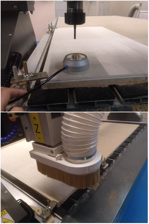
Position the Z0 of the machine: We will put the milling cutter of the machine in a position of the material that is flat: 6.1 WITH SENSOR: We will place the height sensor under the milling cutter (without touching it) and on top of the material. We press ON / OFF + MENU. First we will press the MENU key and without releasing we will press ON / OFF, we will now release both keys at the same time. The motor will slowly lower and the cutter will touch the height sensor, when it touches the Z axis will go up and the height taking will be finished. 6.2 WITHOUT SENSOR: We locate the position we want and press ON / OFF + ZC0 and then mark CLEAR Z.
-
Once we have the XY0 and the Z0 we can press ORIGIN / OK (in case we have moved the axes) so that they return to 0. It is not a necessary step since the DSP has already saved the XY0
-
Set the axis of rotation to 0: Press ON / OFF + ZC0 and then mark CLEAR A.
-
Load the machining files.
9.1. We press RUN / PAUSE DELETE and the DSP will show us two options. Here we must choose where we have saved the machining file. The 1st option (U Disk file list) is the one we will use since we will always use the pendrive. We therefore press ORIGIN. 9.2. The DSP will show us a list of the files that are on the pendrive. We will move to the file we want and accept it with the ORIGIN / OK key.
9.3. Next we must adjust the machining settings, which is as follows:
-
WorkSpd: Work speed when the cutter touches the material. Engraving and cutting speeds can range from 2000 to 6000. For more delicate operations we can reach 1000-200. The operator’s experience will tell these values.
-
FastSpd: Working speed when the cutter moves in the air. Maximum movement speed of the milling machine.
-
SpdScale: 0.500. Percent of WorkSpd speed at which the mill will begin work.
-
FallDown: 0.5. Do not modify this value.
-
-
Press ORIGIN / OK and the job will start. And turn on the aspiration.
-
While the work is being carried out we can make the following changes:
- Change the speed to the motor: Z + or Z-. From 1 to 8 speeds.
- Change the working speed: Y + or Y-. From 0.1 to 1.00 (it would be from 10% to 100%).
8.1.3. Runout
Runout is the tendency to rotate the tool around a center point that is not the center of the tool. Causes the tool to wobble rather than rotate cleanly and increases chip loads. It is very bad for the useful life of the tool, so it is good to know more about it.
It must be taken into account if it is observed that the milling machine changes its behavior. In principle our milling machine should not give problems because it is new.
8.1.4. Alignment
To ensure that the milling work does not come out of the work material, it is important to ensure that the edges of the material are aligned with the axes of the machine, especially for large milling.
To achieve this we follow these steps:
-
Align the work material with the edges of the hammer material, which should be aligned with respect to the machine since it touches an edge of the work table.
-
Check the alignment by moving the spindle along the x and y axes and measuring the distance to the edge.
8.1.5. Feed Rate
We have found information on how to calculate it on this website.
The feed rate used depends upon a variety of factors, including power and rigidity of the machine, rigidity of part hold-down, spindle horsepower, depth and width of cut, sharpness of cutting tool, design and type of cutter, and the material being cut.
One thing to remember is to make chips not dust. Chips will help by removing the heat produced in the cutting process thus increasing tool life and improving edge quality.
Feed rate is calculated using the following equation:
Feed = N x cpt x RPM
N - number of cutting edges (flutes)
cpt - chip load (chip per tooth) is the amount of material, which should be removed by each tooth of the cutter as it rotates and advances into the work. (mm per tooth)
RPM - the speed at which the cutter revolves in the spindle. (Revolutions per minute)
Feed Rate calculation
-
Material: Plywood wood, width = 10.2 mmm approx.
-
Milling tool: Straight flute type, d = 6mm, N = 2 edges.
-
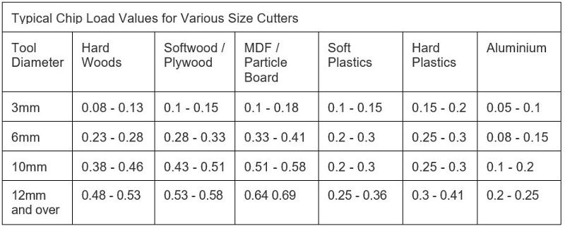
Chip Load: According to Chip Load table, ctp = (0.28-0.33)
-
Calculation:
Feed = N x cpt x RPM
Feed = 2 x 0.3 x RPM
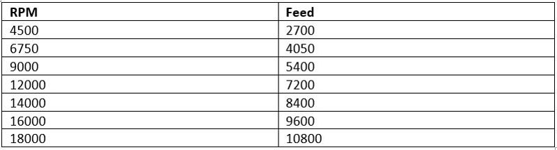
We will test milling at different speeds taking the calculated speeds as a reference.
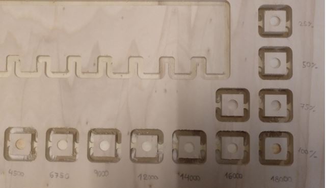
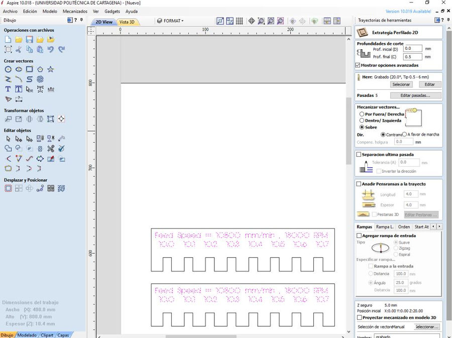
We have made the cut at different speeds of Spindle (the speeds that the machine allows) and rate speeds (starting from the speed that we previously calculated). There is no great difference in the surface finish. It seems that at 18,000 RPM and at 10,800 mm / min the result is somewhat better.I also haven’t seen smoke come out at low rate speeds
8.1.6. Pressfit test
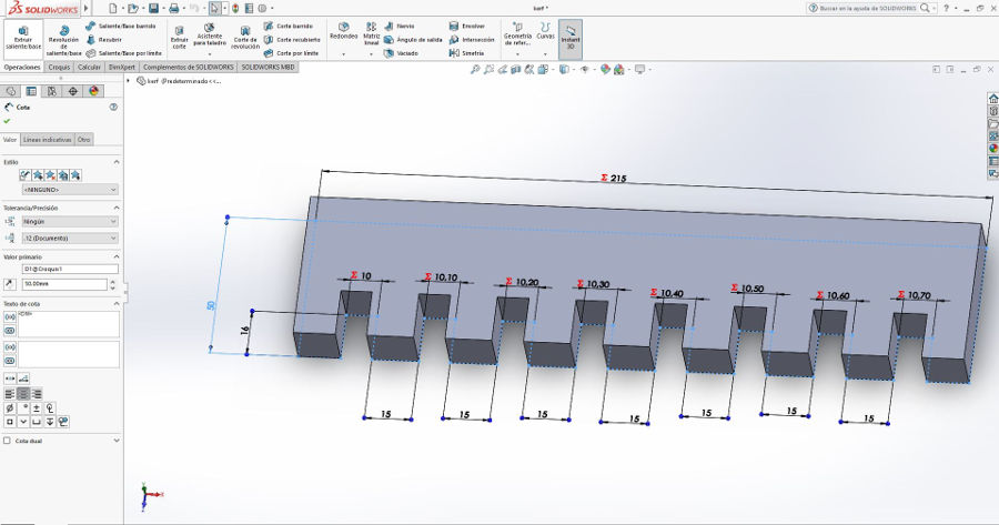
To check the pressfit we have designed a piece with different lace measurements. We have cut it with the following parameters: 10800 mm / min and 18000 RPM with the milling tool (Straight flute type, d = 6mm, N = 2 edges). In addition, we engraved a text at a depth of 0.5 mm with a V Carving type mill 20º x 0.2 x 3 mm.
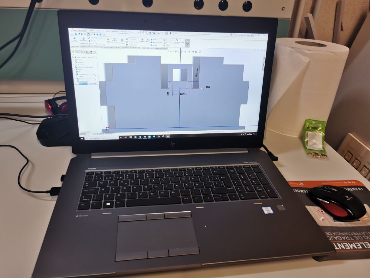
El diseño lo he hecho utilizando Solidworks. Creo un dibujo a partir de la pieza y exporto la imagen como dxf.
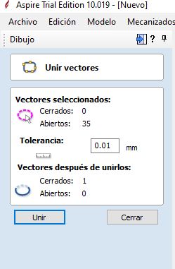
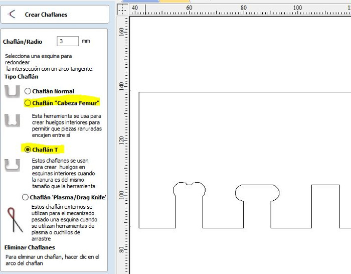
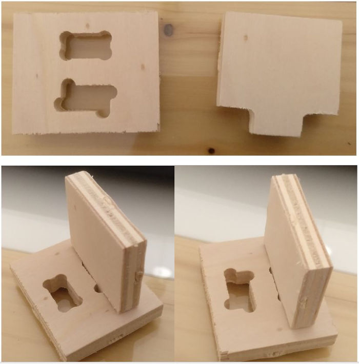
To import vectorized images as dxf in the Aspire software we have to click on “Import vectors from a file” (1). And then make sure that the contour is closed by clicking “join open vectors” (2). Also we have added a text to record the measurements of the different pressfits using the “Draw text” tool (3). Finally, we have used the “Create chamfers” tool (4) to round the inner corners that the cutter could not enter. We use the T-Bone y Dog-Bone types.
Results:
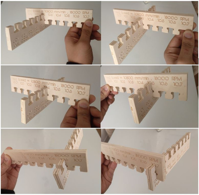
The greatest tightening I get with 10.02 mm although it costs a little to fit the pieces, therefore when designing joints we will take the same thickness of the material as a measure.
We have also tried other joints.
8.2. INDIVIDUAL ASSIGNMENT
To carry out this individual assignment I have gone through several ideas :
First Álvaro and I agreed to make furniture that could be used in the Fablab, and we decided that he would design a desk and I the chair that would serve as the desk.
Just when it was time to do this assignment, the Fablab closed due to COVID-19 and I started to design the chair but I didn’t finish it and also I wouldn’t have been able to manufacture it since I didn’t have access to the CNC.
So later, in full confinement, Candela, my youngest daughter, asked me to make her when she could go to the Fablab, a cabinet-shelf for the bathroom that she uses and she wanted it to be similar to one that He saw one day in the window of a hairdresser when he was walking with his father, and he took a picture of him. It was something like this:

I also started designing a really cool piece of furniture, but assignment work piled up alongside classes, work projects, and health issues, and I couldn’t bring this idea to fruition either. It is something that remains pending …
With all this history, finally, when I had my final project very advanced, the idea arose that it would be convenient to introduce the CNC milling technique in one of the phases of my final project, since I had used 3D printing together with other disciplines but not he had fabricated nothing subtractive.
In this mission I ended up designing two large-format structures to create a frame to hold the infrared window on the sheet metal bending machine and for the infrared traffic light to control access for people with fever symptoms.
Both projects are also documented in the development section of my final project (link).
8.2.1. Manufacture of parts with CNC milling machine
8.2.1.1. Design of Wood pieces to cut on the CNC milling machine
As I have explained before, for the case in which the infrared window is implemented in a large format machine tool, as is the case with the roller bending machine where I want to put it, the same method could be followed, completing more links with more sensors.
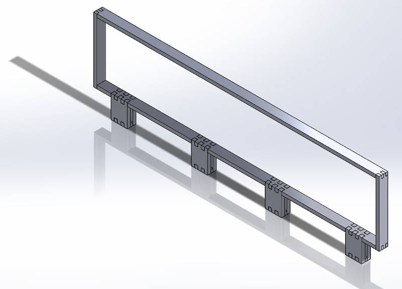
But, as an alternative, I have decided to create a frame design adapted to the bending machine, and then make it out of wood using the large format CNC milling machine. In this way I will also optimize the space and the arrangement in it of the sensors so that they cover the largest possible surface. Since I have a limited number of sensors to do my final project.
This is my CAD frame design:
This would be the rack with the sensors:
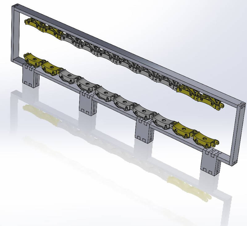
With textures it would look like this:
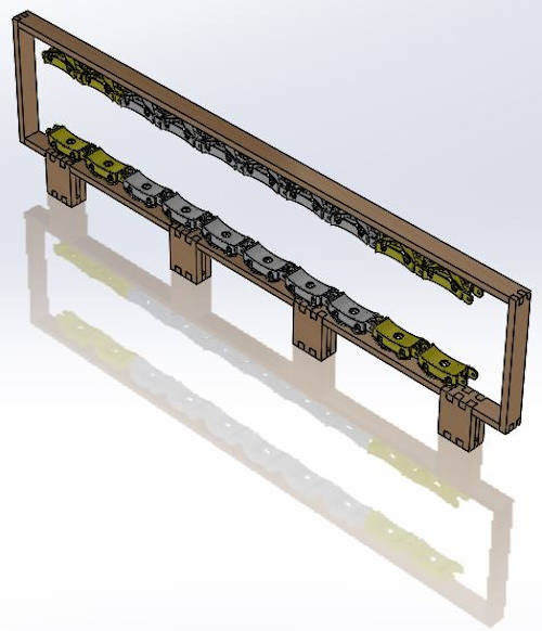
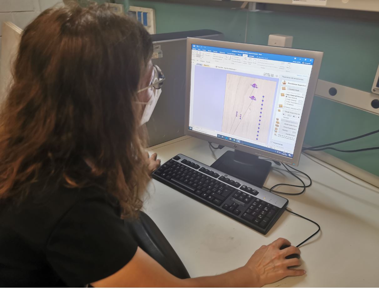
This is an animation of his assembly sequence:
I also thought about the application that occurred to me to give this infrared technology during the week of the applications and implications assignment, and decided to design the chassis of what would be the access control device with which you can control the temperature of the personnel that intends to access a shared space, in this way it will be possible to know if it presents this symptom and decide if access is allowed.
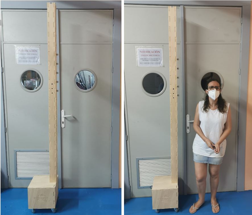
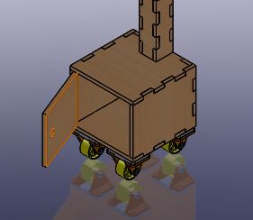
So I also designed the wooden structure where to put the sensors at different heights for people of different stature and that had a sound and light alarm that would warn when the electronic control box also located in this structure detected a feverish temperature in the person who pretended to access. This is the structure of my Infrared traffic light .
The design is this:
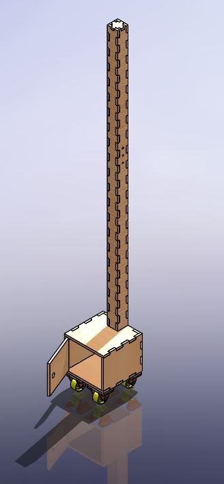
It is a portable wooden structure that has the electronics developed for the sensors of the IRW security device integrated, but now the purpose is to measure the temperature of the people who try to access a place where they will share space with other people.
In the lower cabinet that has wheels to facilitate its portability, will be the electronic control components.
The electronics is a replica of the one created for the IRW sfety device.
In the mast, the sensors go to different heights, so that it can be used for people of different stature. (I already mentioned this before).
And also a green led that gives entry permission, and a buzzer and a red led that warn of the alert of possible illness in the person who wants to access, since their temperature is higher than normal.
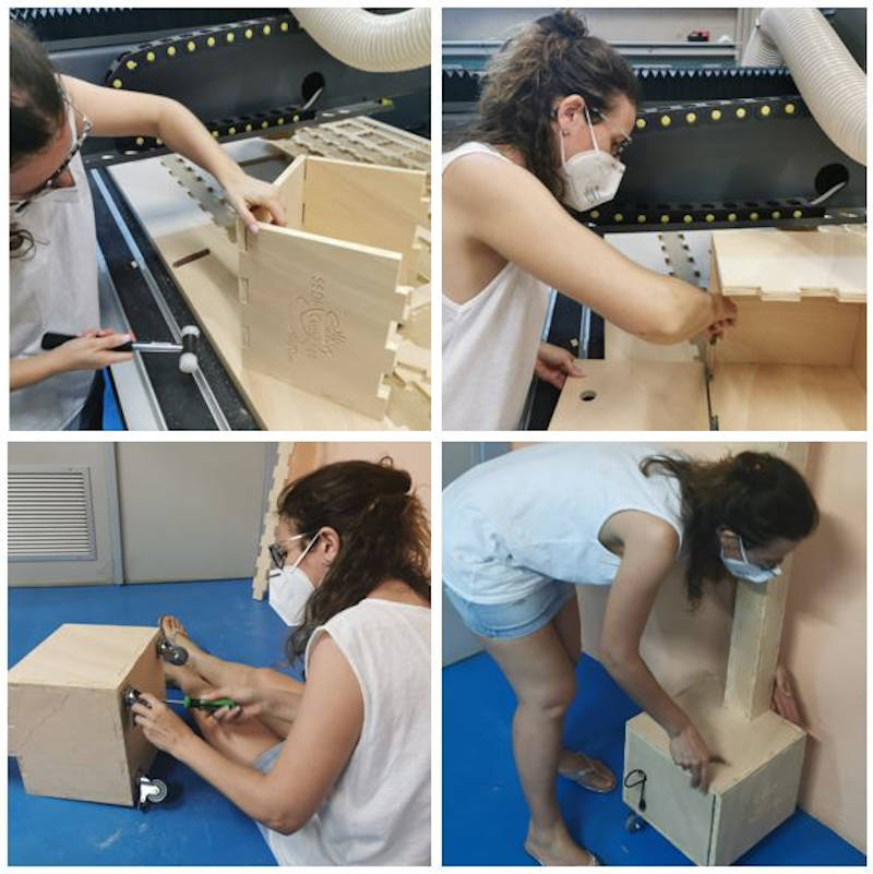
All parts have been manufactured on the CNC milling machine and have been assembled in the following order:
8.2.1.2. Configuration of files to send to a CNC milling machine
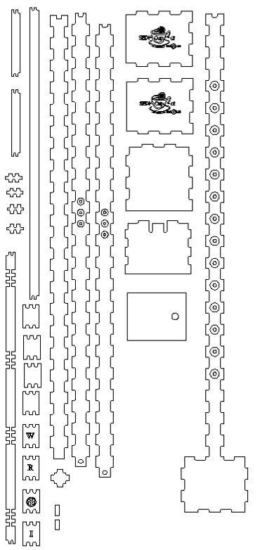
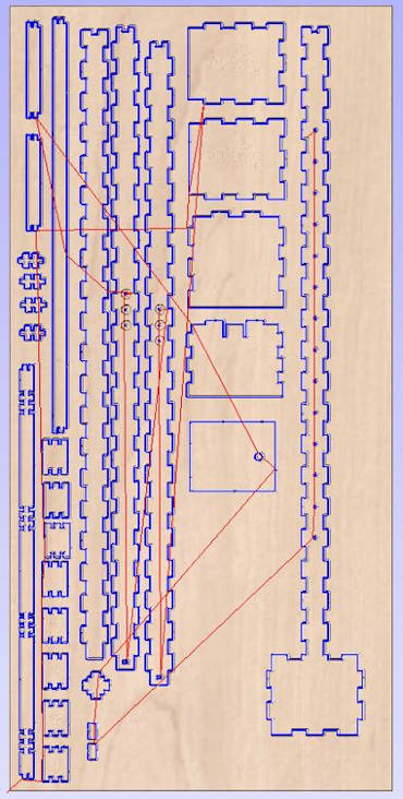
I created the manufacturing drawings of each piece in dxf of both designs that I imported from the milling machine software that is Aspire, and prepared the configuration to mill a 2.5m x 1.2m and 15mm thick, with the exploded view of both designs.
The result was this:
8.2.1.3. Preparation of the CNC milling machine
Then, I prepared the CNC to send the file and the milling process to take place:
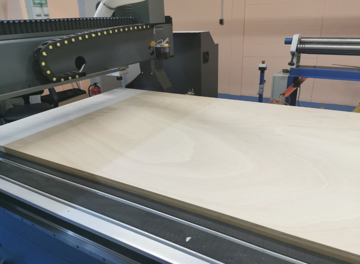
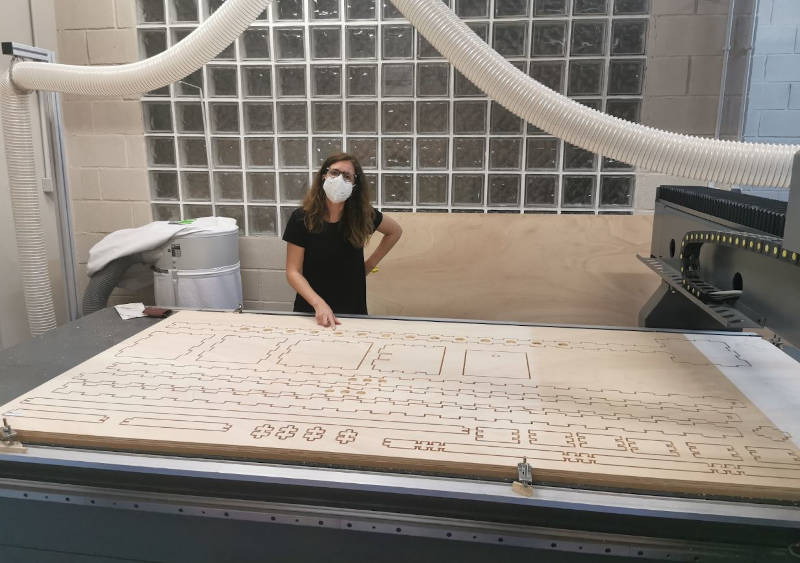
The milling machine did its job well:
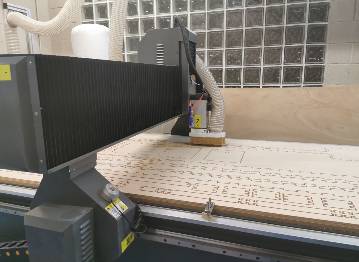
The result of the milling was this:
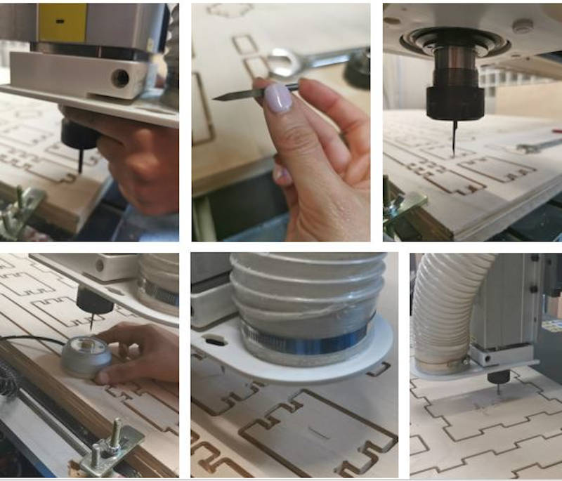
I made a tool change to engrave the wood with the IRW logo and our SEDI-CUp-ct Fablab.
8.2.2. Assembly of parts made with CNC milling machine
I separated the pieces of the wooden board and did the frame assembly:
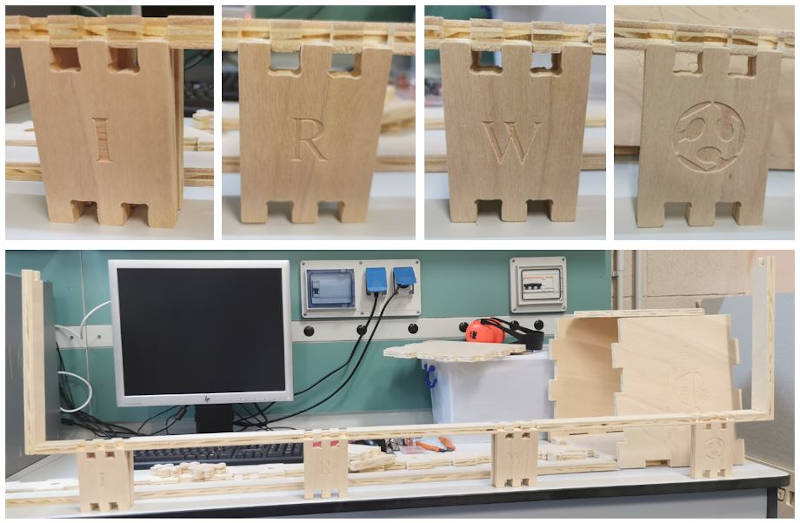
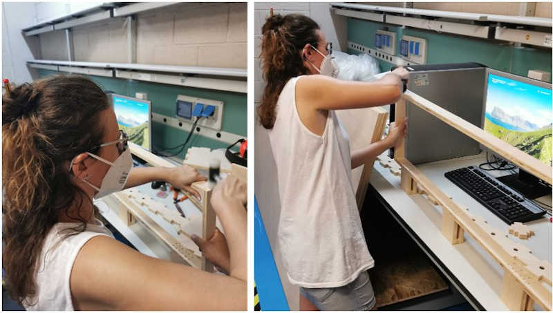
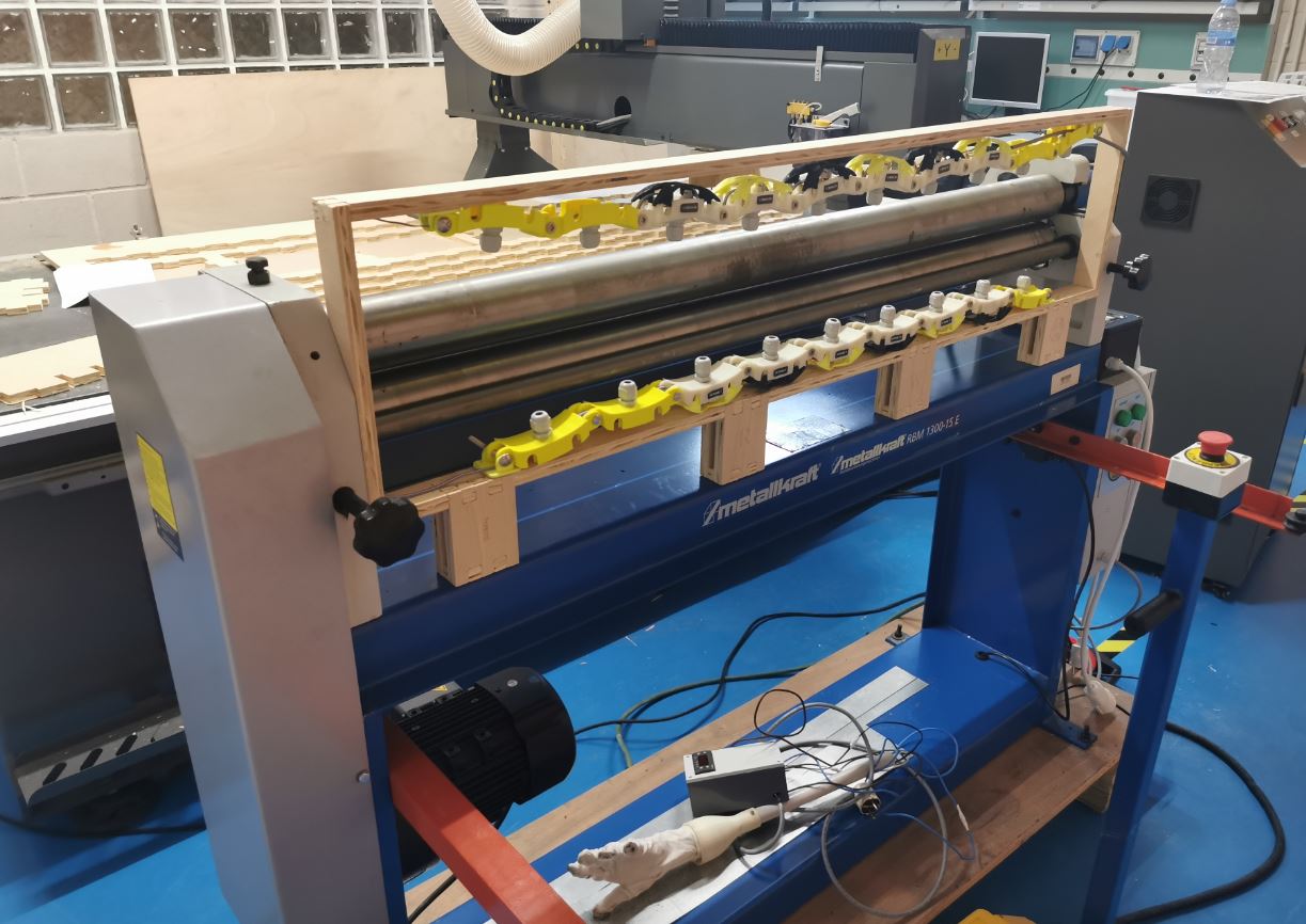
This is the frame mounted on the sheet metal roller bending machine.
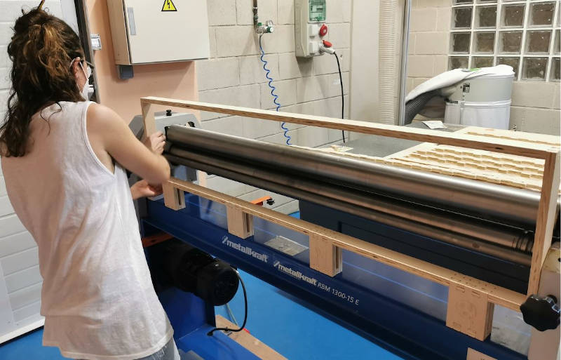
I’m happy, it was perfect !!!
Next, I assembled the infrared traffic light parts:
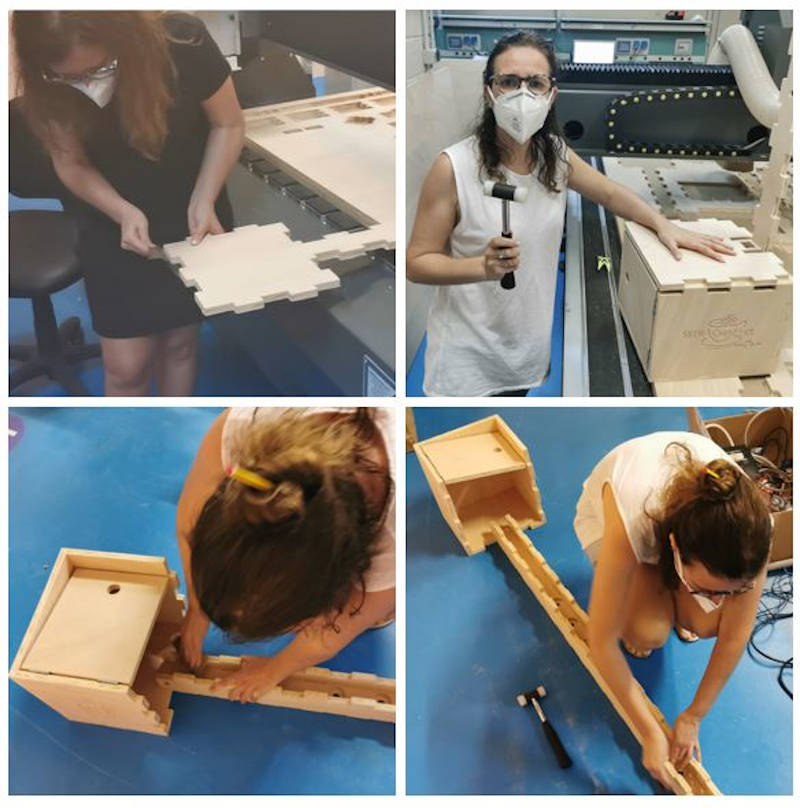
8.2.3. Results
This is the result of both assemblies mounted and fulfilling their operation.