6. 3D SCANNING AND PRINTING
This week I made the group assignment with my co-worker Álvaro Macián, we are both from Sedicupct-Fablab and our local Fabacademy node is FabLab León.
In my individual assignment I have made a design that I have then printed in 3D and I have done the scanning of my little daughter, which I will then print as well.
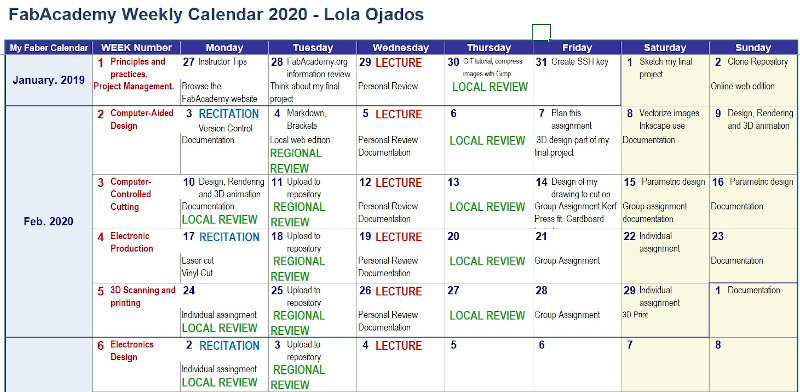
I have continued using my weekly planning in which I have updated my activity in FabAcademy
Post-assignment Documentation:
Update week 6:
In this week’s Random I got a prize.
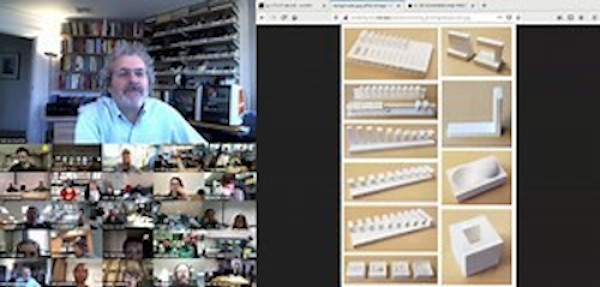
In the Review for week 6, on March 4, Neil asked me about my assignment for this week.
I was the first student that week to exhibit, I hardly have time to sit at the computer when I heard my name.
What nerves!
It has been very stressful, since I don’t control the language well, and I find it difficult to understand and express myself in a live conversation. But it has been a good experience and I have learned from their contributions to my work.
Especially since I have learned of the existence of software called GRABCAD.
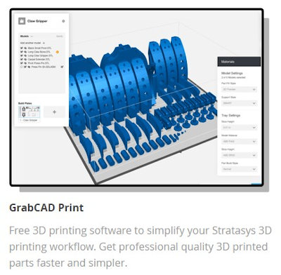
More information about GrabCAD, in this Link.
This software allows the configuration of the support material for the 3D printer Dimension bst1200 es, which we have at SEDI-CUp-ct FABLAB.
(In this link you can access the BST 1200 BST / SST 1200 User Guide).
Until now, the printing parameters and the configuration of the parts to be printed have been done with the printer’s own software CatalystEX.
This software is very closed and does not allow practically the modification of some parameters that are imposed in your printing configuration.
I have started testing with GrabCAD and I think this is going to be a real discovery !!!!
I would have liked to tell Neil more carefully about the content of the Extra-Assignment that I have included in the documentation for this week, the doping of materials as well as the recycling of them, crushing and extruding. The surface finishes that we give to the materials and some of the applications that we give to the scanning processes …
But it was very good to be able to tell Neil a part of what I have done in this assignment.
This is the link to the video of the review, I participated right at the beginning of it.
6.A. GROUP ASSIGNMENT
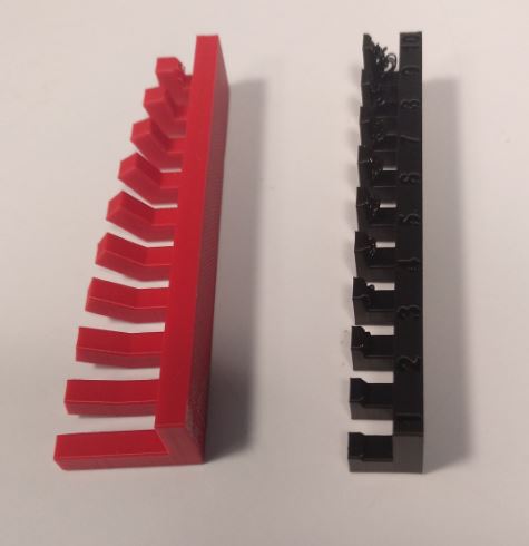
Test the design rules for our 3D printers
This group assignment was done by my partner Álvaro Macián and I together from our local node in SEDI-CUp-ct FABLAB, we are remote students of the Fablab León node.
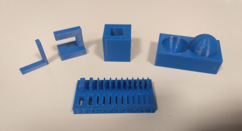
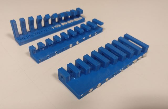
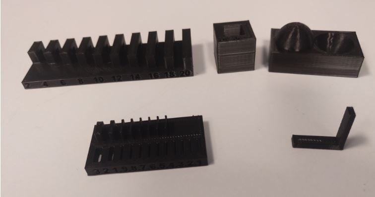
To perform the tests we have used the Neil models.
Our 3D printers are: - Dimension bst 1200es. - Ender 3 Pro. - Object30 Pro.
6.A.1. Dimension bst 1200es
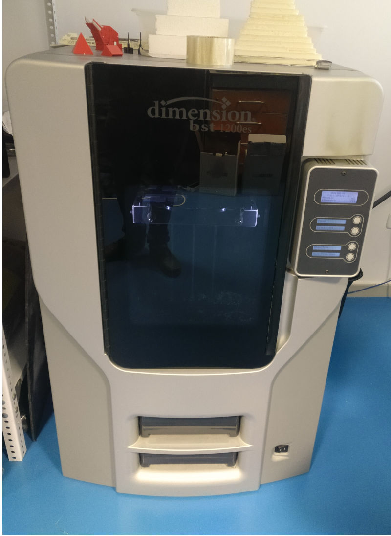
6.A.1.1. Characteristics
This printer is of the FDM type.
-
Modeling material: ABSplus in ivory, white, black, red, olive green, nectarine, fluorescent yellow, blue or gray.
-
Support material: Breakaway Support Technology.
-
Measures: 254 x 254 x 305 mm.
-
Layer thickness: 0.254 mm (0.010 in.) Or 0.330 mm (0.013 in.) Of ABSplus support and modeling material accurately deposited.
ASB plus has a different composition than the standard ABS, improving its mechanical properties.

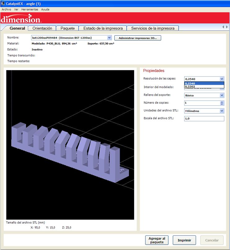
6.A.1.2. Software and print settings
This 3d printer necessarily uses its own software, CatalystEX.
We configure the layer resolution. We select 0.2540 mm to obtain a better finish.
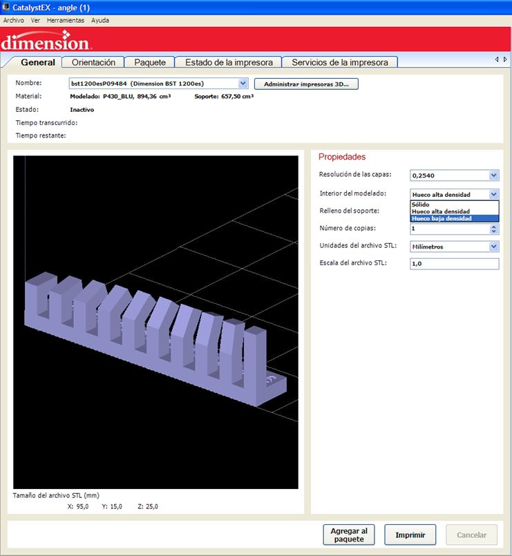
In the Interior option of the model we configure the filling density of the model. We select the “Low density gap” option to speed up printing time.
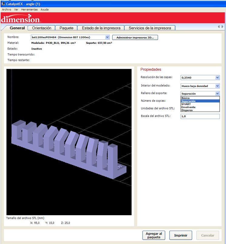
Support padding configuration. Always print with support material. We select the “Separation” option because it is the one that uses less support and it is assumed that it will be easier to remove it.
NOTE: During my review intervention, in the random on March 4, I discovered that this can change using software like GrabCAD.
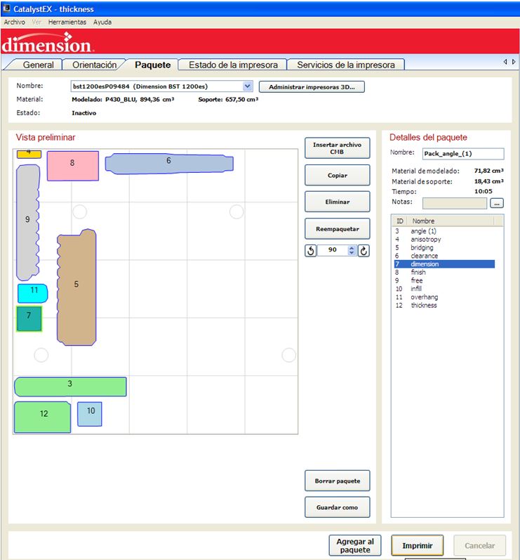
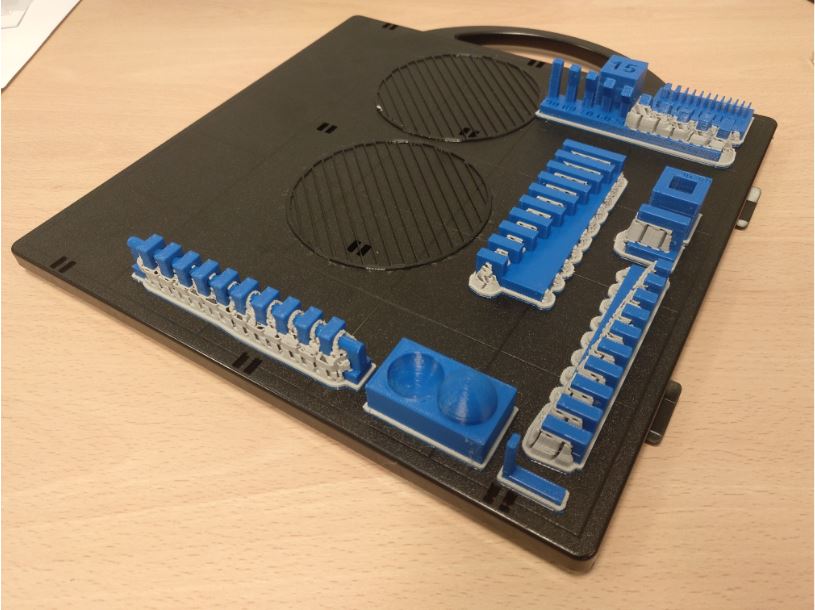
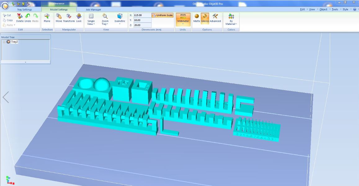
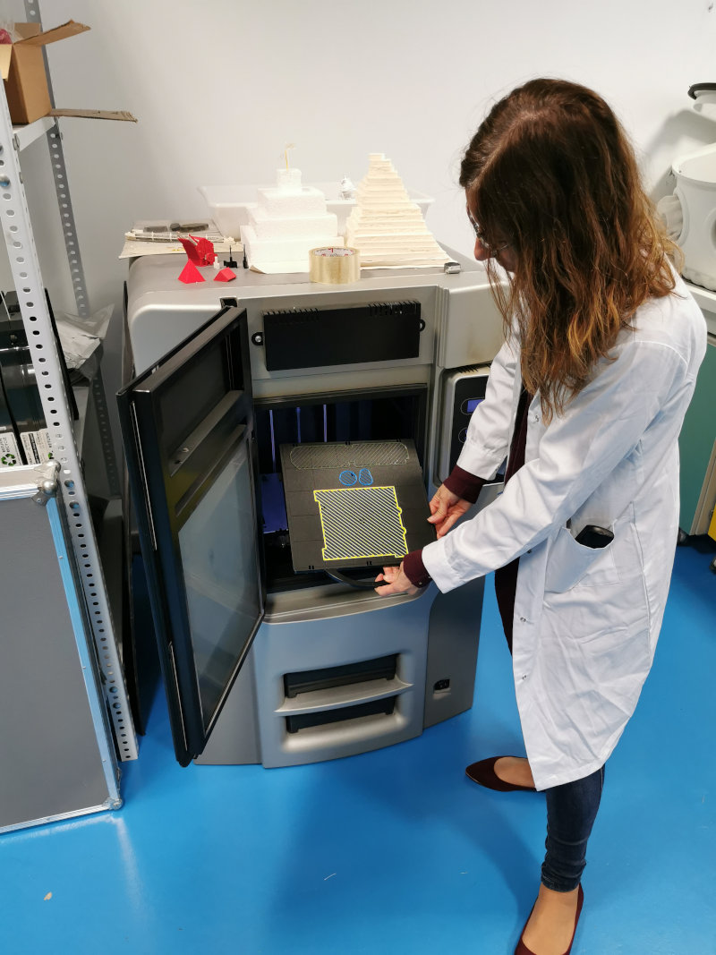
The pieces must be distributed in the printing tray without covering the circles (targets) which the machine uses as a reference. The trays are expensive, so we reuse them until there is no gap left unused (on the surface that has occupied a printed piece can no longer be reprinted). Tetris moment.
6.A.1.3. Results
-
The surface finish looks smooth.
-
The bridges and overhangs are perfect since it always uses support material.
-
The minimum wall thickness is 1 mm, if in the design the thickness is smaller it will also print it at 1 mm. For slots if it reaches 0.1mm.
-
The difference between the actual and design thickness is + 0.1mm for wall and -0.1mm for holes.
-
The support material costs a lot to remove in narrow spaces. So it is not recommended for such parts. It must be taken into account in the design.
-
Vertical surfaces break more easily than horizontal surfaces under stress. Although it holds a lot because it is ABSplus.
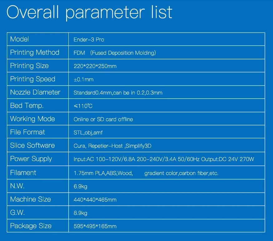
6.A.2. Ender 3 Pro
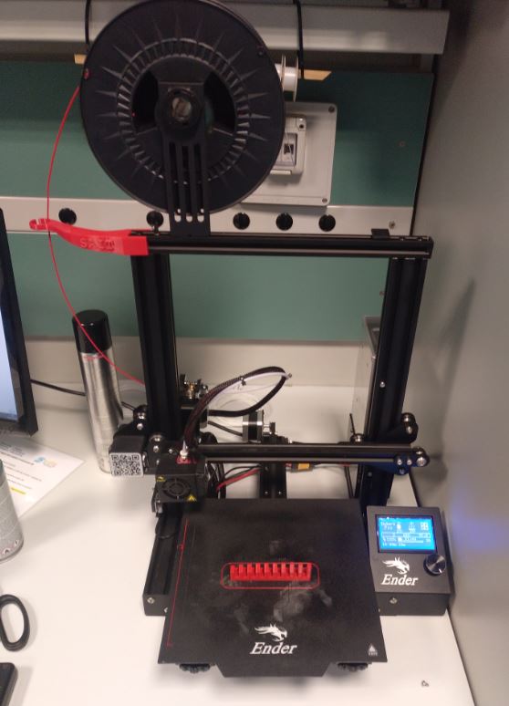
6.A.2.1. Characteristics
This printer is of the FDM type.
6.A.2.2. Software and print settings
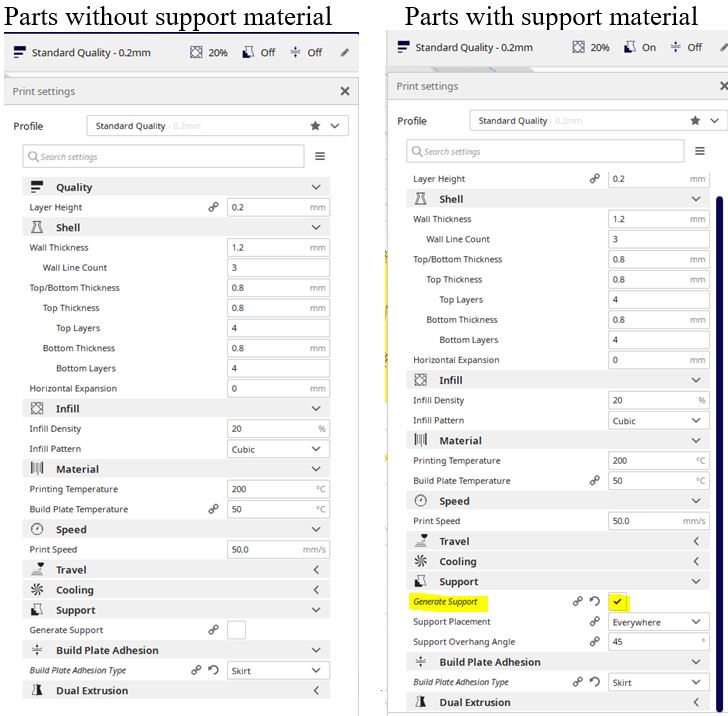
To use this printer we use Ultimaker Cura , free software. We use the 0.4 mm diameter nozzle.
We configure on the one hand the pieces without support material and on the other hand the pieces with support material.
6.A.2.3. Results
-
The surface finish looks smooth.
-
The bridges are perfect.
-
The lower part of the overhangs of more than 3 mm has threads that have come loose. To get a better finish you need support material.
-
The angles look perfect until 20 degrees of inclination.
-
The minimum wall thickness is 0.5 mm. For slots if it reaches 0.1mm.
-
The difference between the actual and design thickness is + 0.1mm for wall and -0.1mm for holes.
-
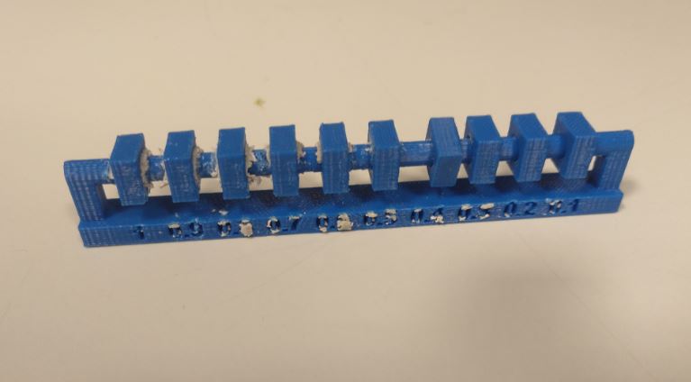
The minimum clearance for joints is 0.2 mm.
-
Vertical surfaces break more easily than horizontal surfaces under stress.
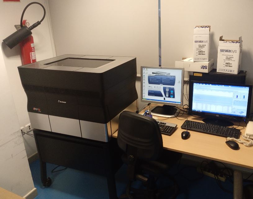
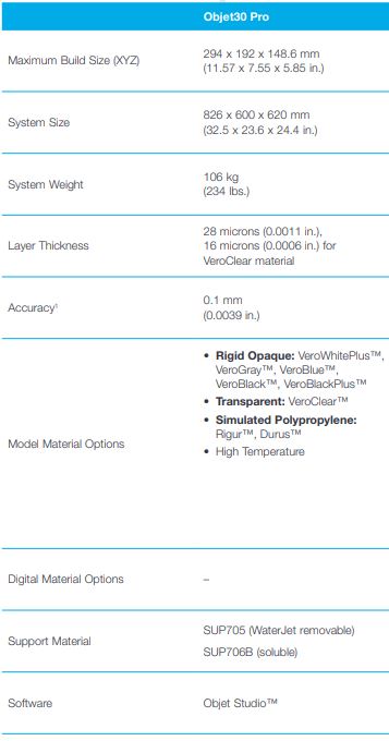
6.A.3. Object 30 Pro
6.A.3.1. Characteristics
This printer is of the Polyjet type.
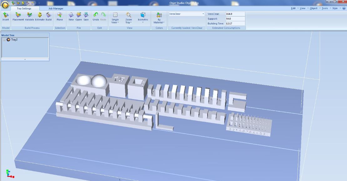
6.A.3.2. Software and print settings
This 3d printer necessarily uses its own software, Object Studio.
It has almost no parameters that can be configured. Always add support material. We can only choose the surface finish (Gloss or matt).
For the tests we have used VeroClear for the model material and SUP705 for support material.
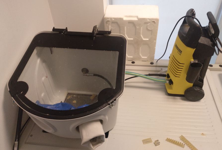
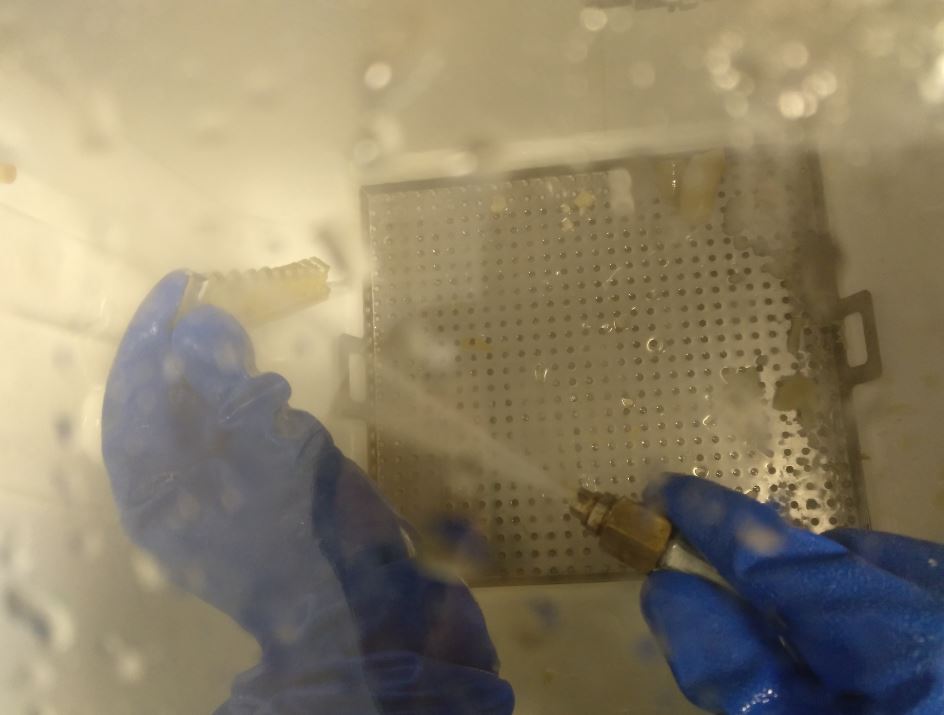
6.A.3.3. Results
To remove the support material a bucket with pressurized water jet is used.
-
The surface finish is perfect.
-
All geometries are perfect.
-
The difference between the actual and design thickness is + 0.05mm for wall and -0.05mm for holes.
-
The minimum wall thickness is 0.1 mm. For slots if it reaches 0.2mm.
-
The minimum clearance for joints is 0.2 mm.
6.B. INDIVIDUAL ASSIGNMENT
In this week’s individual assignment, we had to make a 3D design that was difficult to achieve by subtractive manufacturing and print it in 3D on one of the 3D printers available in our Fablab.
Another assigned task has been to perform the scanning of an object and perform the postprocessing to close and optimize the mesh resulting from the triangulation of the point cloud obtained with the 3D scanner.
6.B.1. Design and 3D printing
The statement of this part of the assignment is:
- Design and 3D print an object (small, few cm3, limited by printer time) that could not be made subtractively.
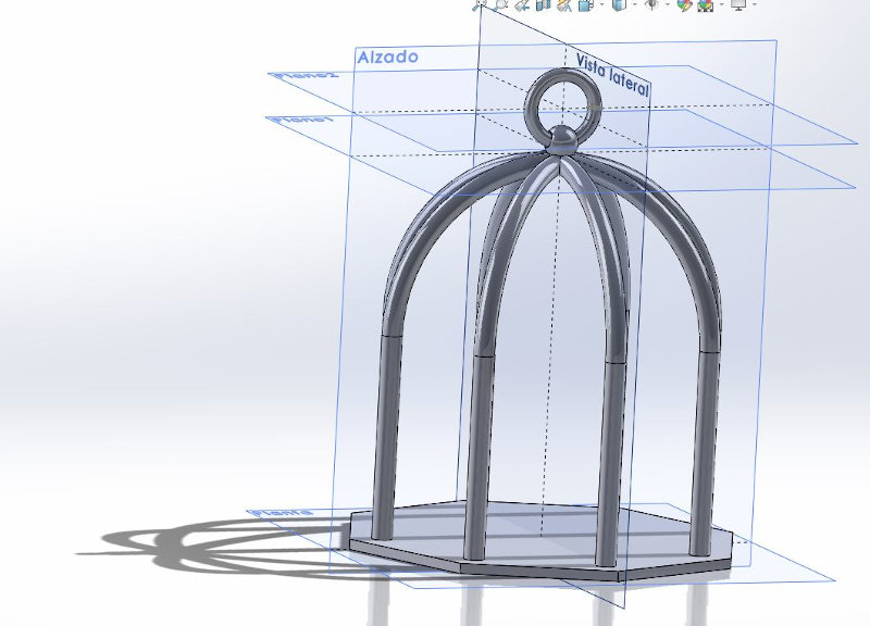
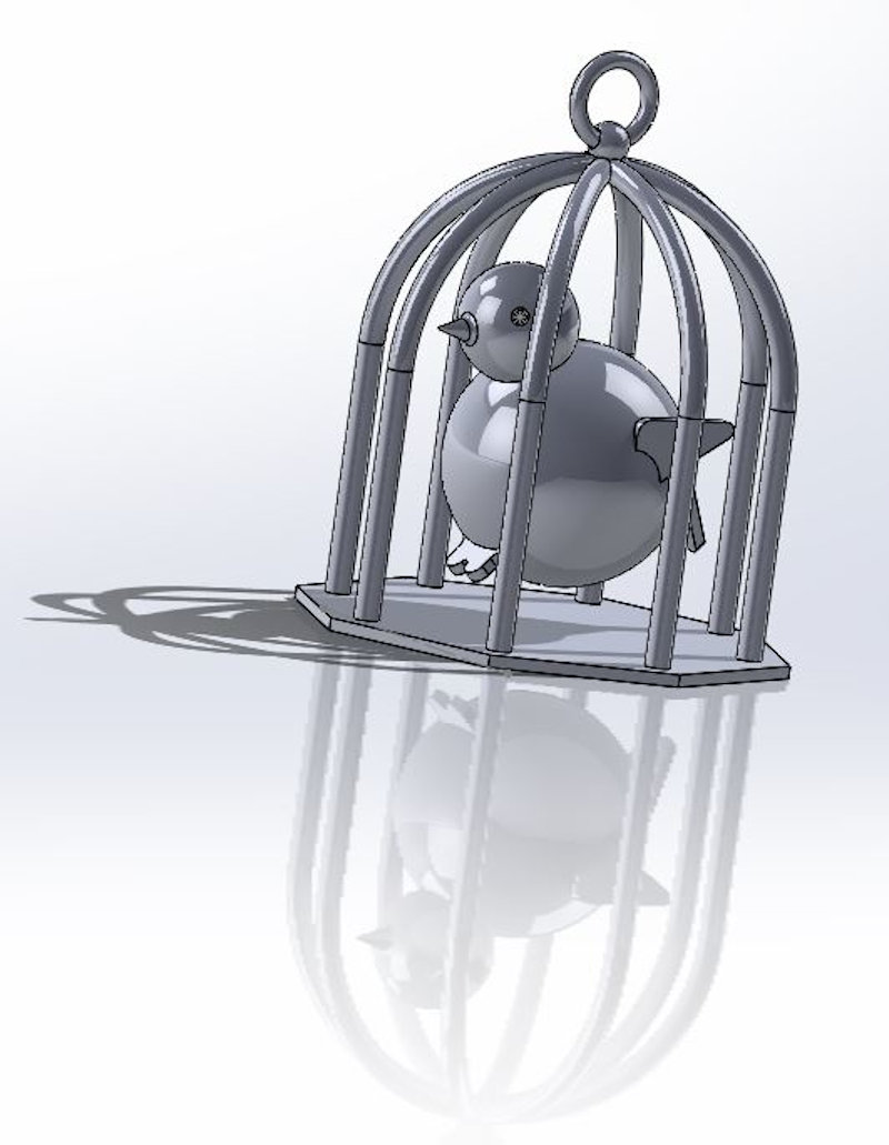
For this part of the individual asssignment it occurred to me to make an object inside another that was difficult to manufacture subtractively, so I thought of a bird inside a cage.
I have not wanted to make a very elaborate design, I have used solidworks and I have created my set of objects that I want to print in 3D.
This is the cage that I designed.
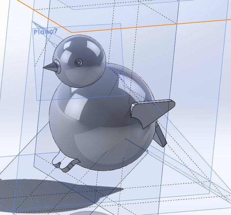
This is the little bird that will be inside the cage.
This is the design of the two objects made with the Solidworks CAD software.
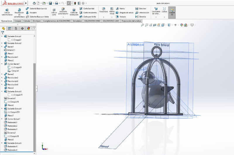
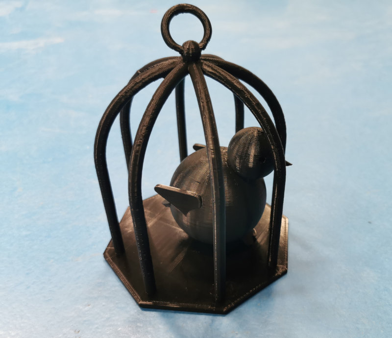
This is the bird inside the cage.
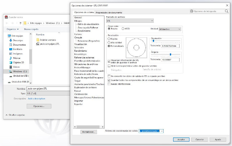
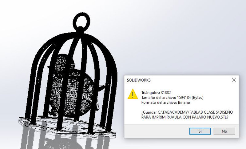
From Solid, I exported my design to stl format.
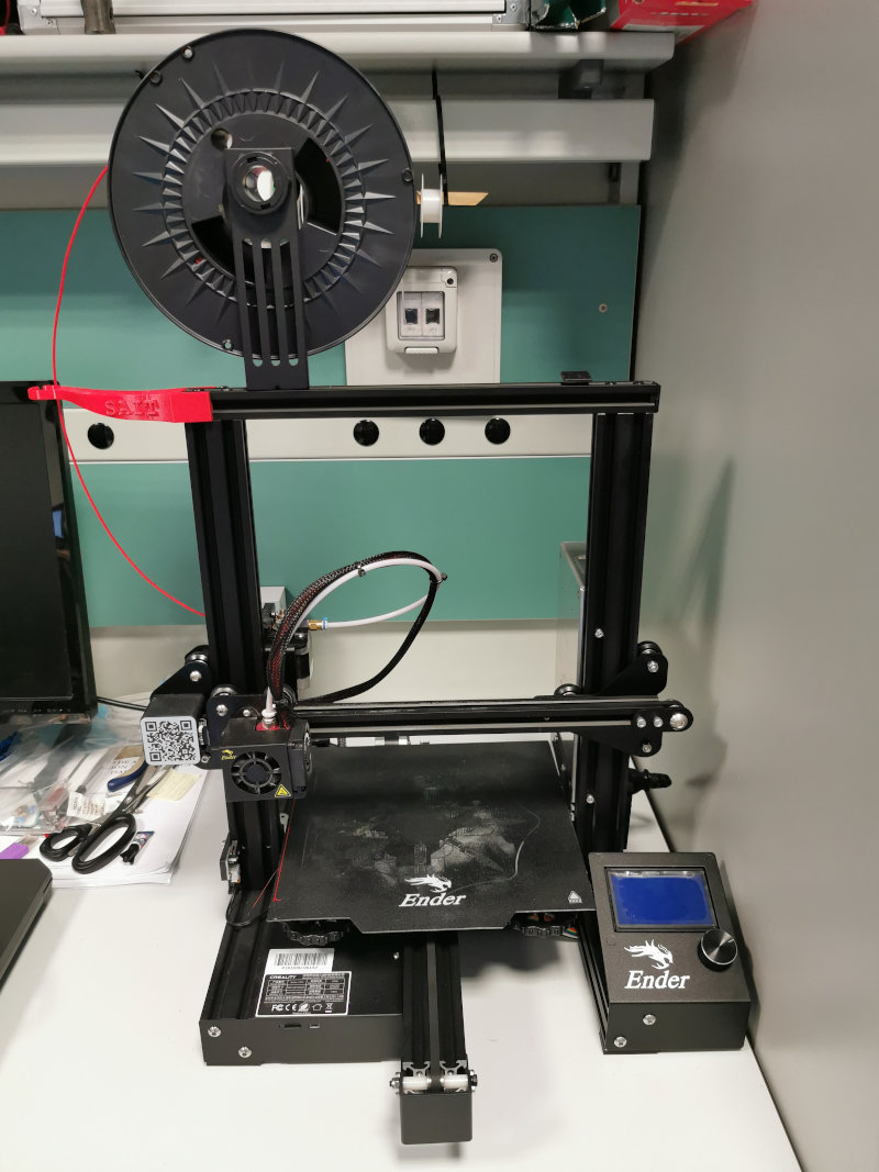
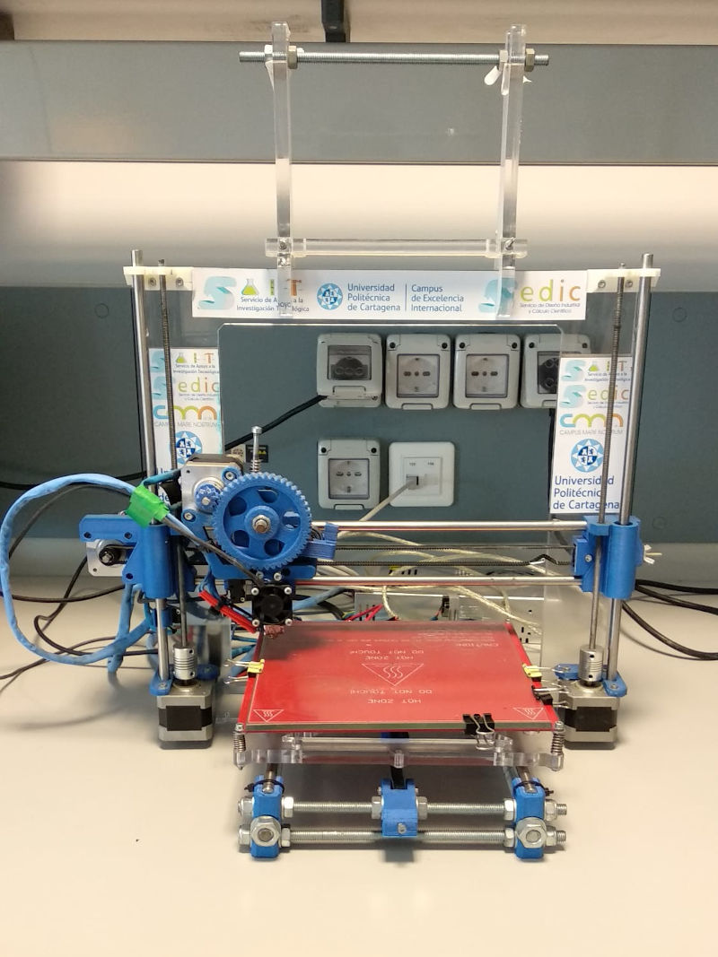
The 3D printer I used is the Ender 3Pro.
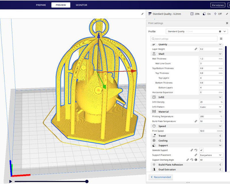
The software used for the configuration of 3D printing is Ultimaker Cura.
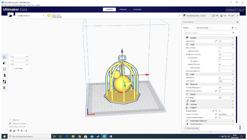
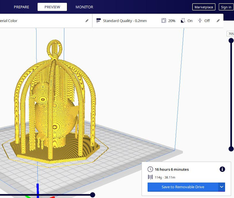
These are the parameters used and the result of the calculation of support material that the machine does with the parameters inflicted.
In total it took about 16 hours to print. (Maybe the little bird is a little fat).
While I went to bed.
The result was this:
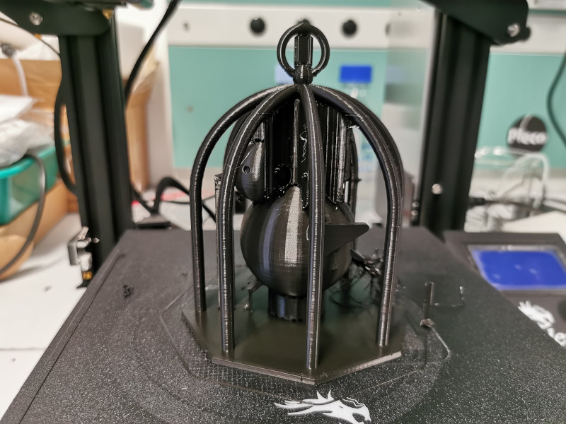
After removing from the machine I removed the support material.
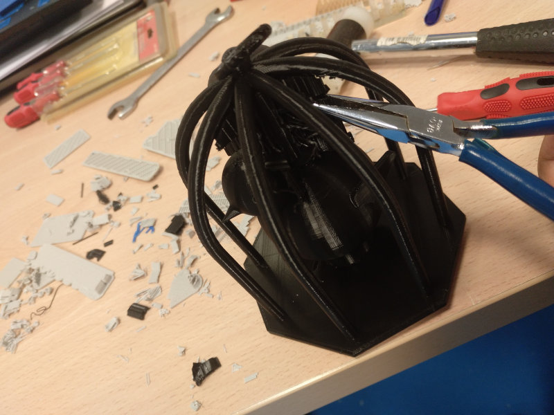
My little bird can move inside its cage.
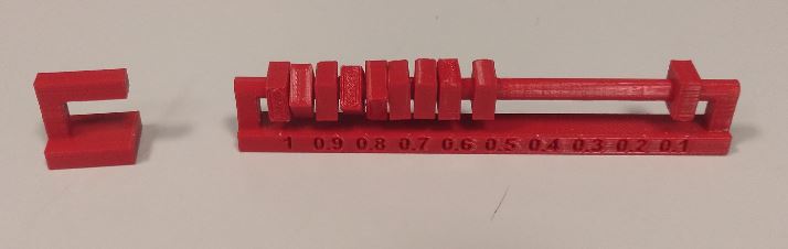
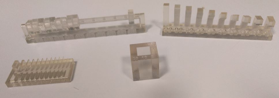
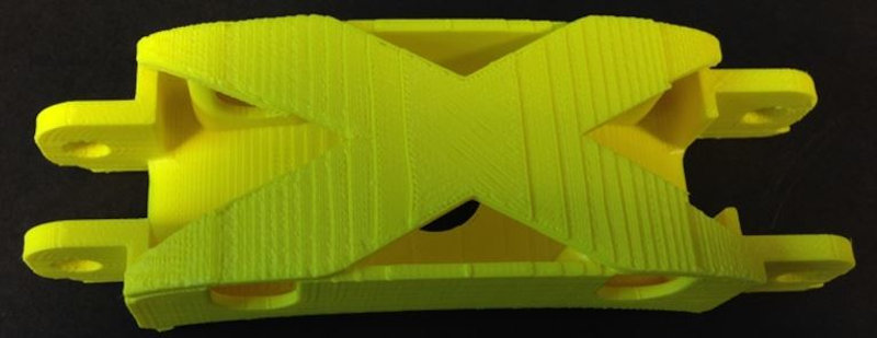
In addition to this task, I have optimized the design of the links in my final work and printed two of them in 3D with their accessories to see what the result was.
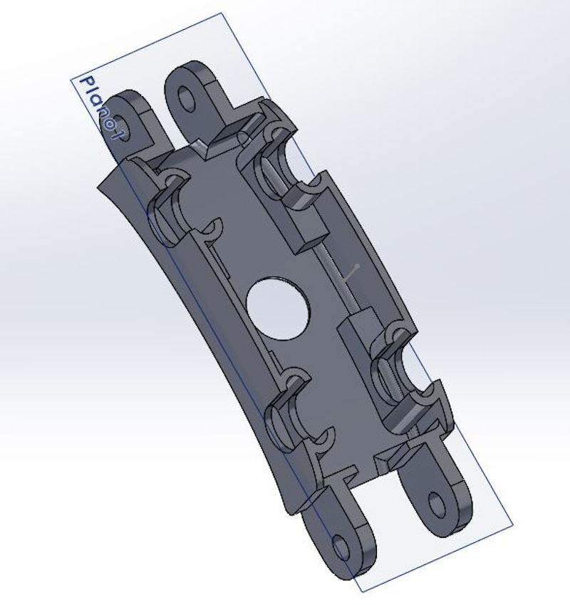
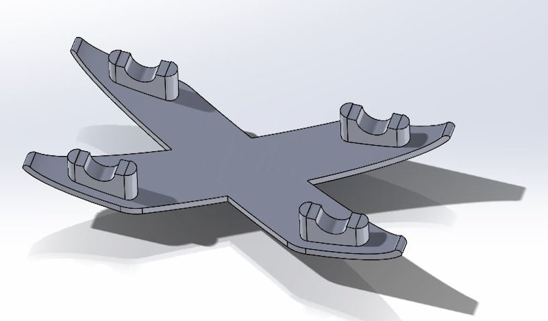
This is the result:
I will update these advances in my final project folder.
6.B.2. 3D Scan
In this case, the assignment statement is:
- 3D scan an object (and optionally print it)
I wanted to scan my little daughter Candela, who lends herself to all my delighted experiments.
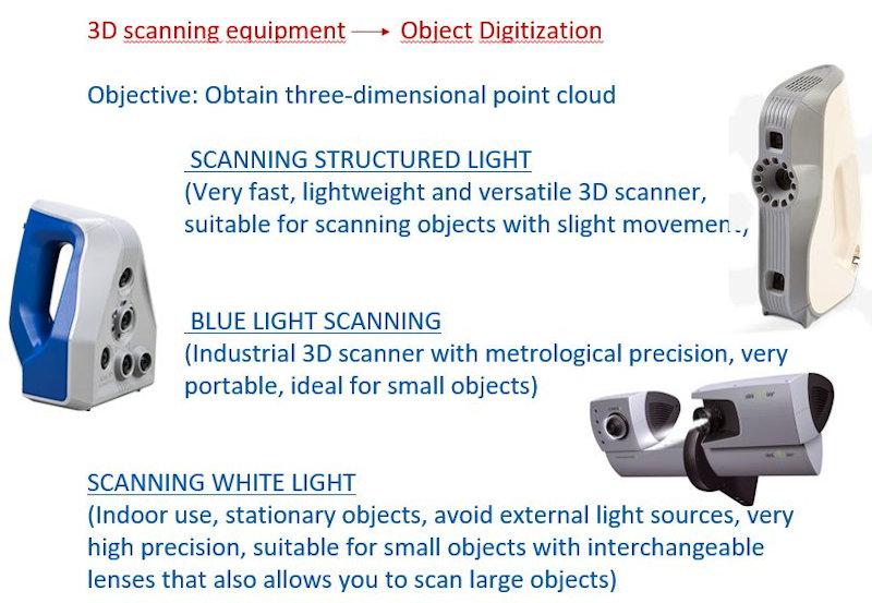
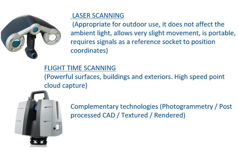
In the research support service (SEDIC) that I lead we have several scanners that we use depending on the object to be scanned and the expected result.
To scan to Candela I have decided to use the Artec EVA scanner (scanner estructured Light).
I have put the scanner on a tripod and I have seated her in a swivel chair, I have asked her to be as still as possible.
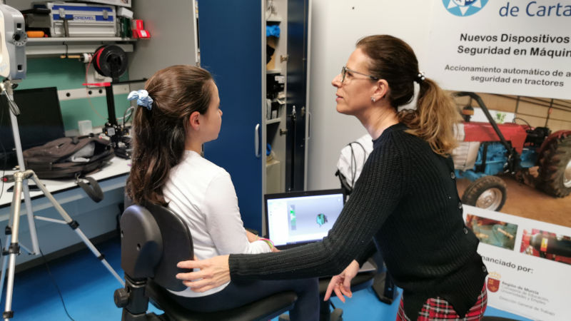
She has fun with these weird things her mother does although sometimes she asks me to look more like the moms of the other children…
This is a video of the Candela scanning process:
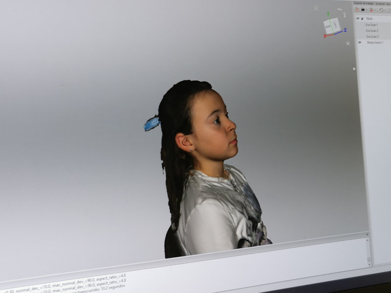
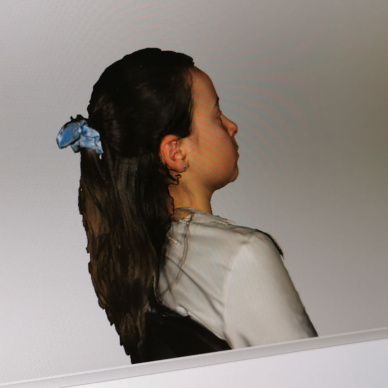
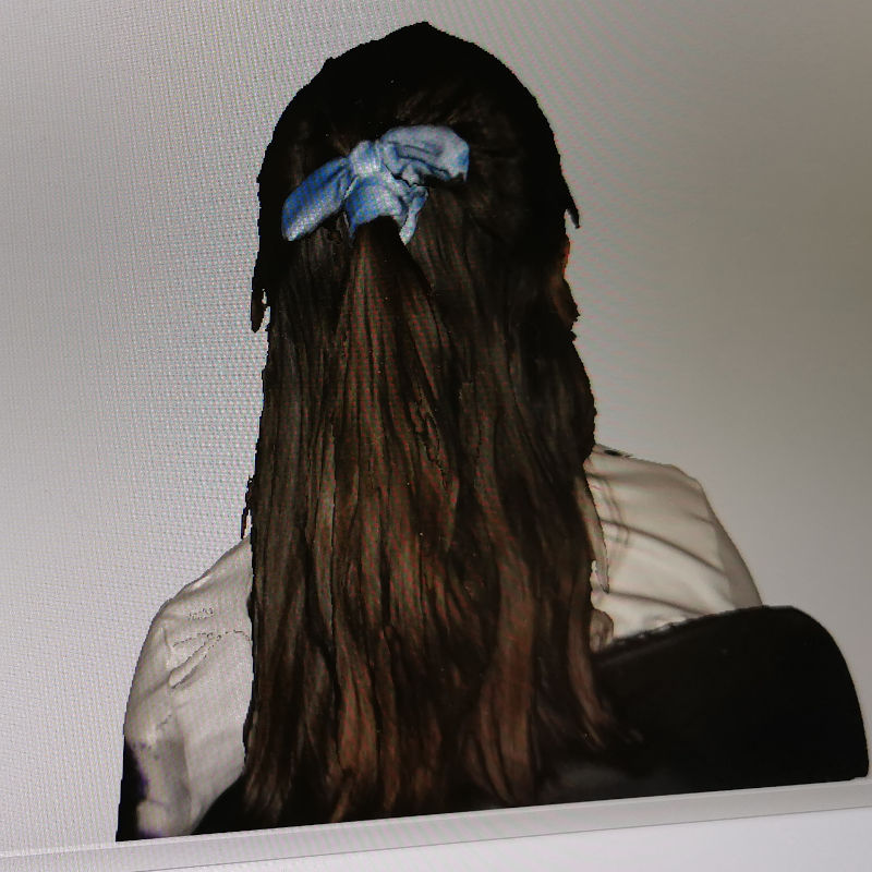
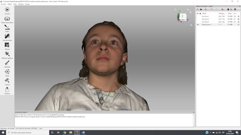
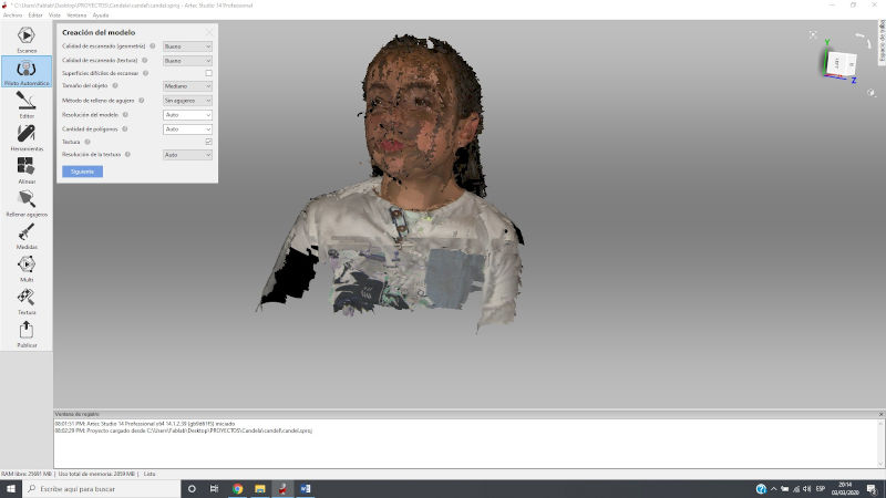
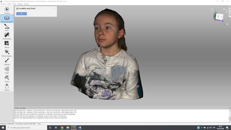
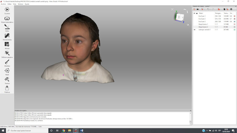
This scanner is also capable of capturing the textures associated with the cloud of points obtained.
Here you can see what I have managed to scan from Candela.
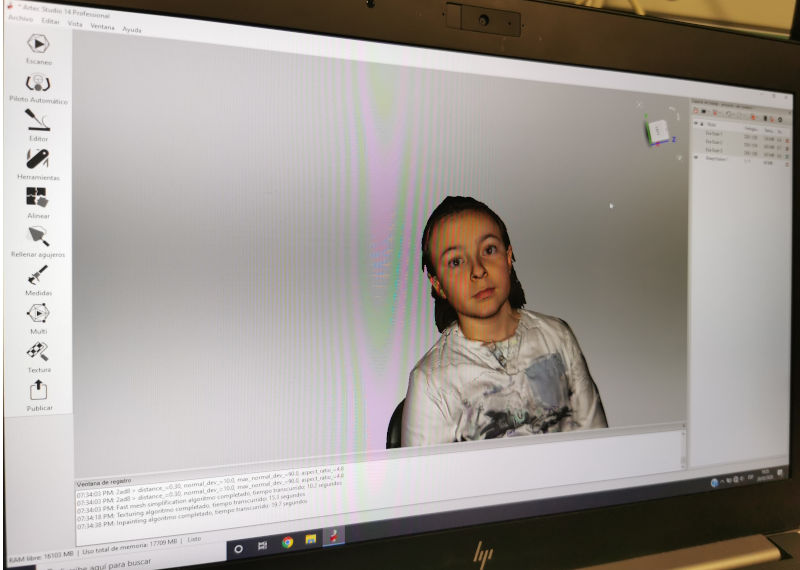
If I stop viewing textures and keep the scanning part that I want to try to try to print the resulting mesh in 3D, it looks like this:
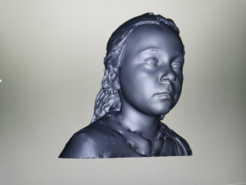
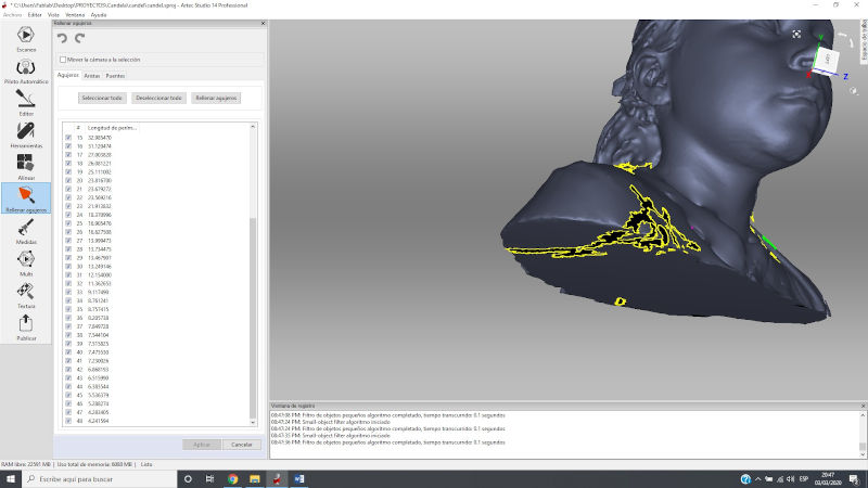
The most laborious has been to close the mesh.
From the ArtecStudio scanner software, I have located the mesh gaps and tried to close them with various tools available in this program.
This process requires patience, skill and some experience.
From now on:
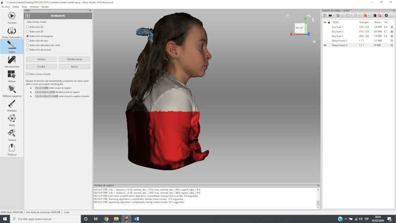
I check the bad overlays of the scan.
And I delete the parts of the cloud of points that deviate and do not match the rest of the shots.
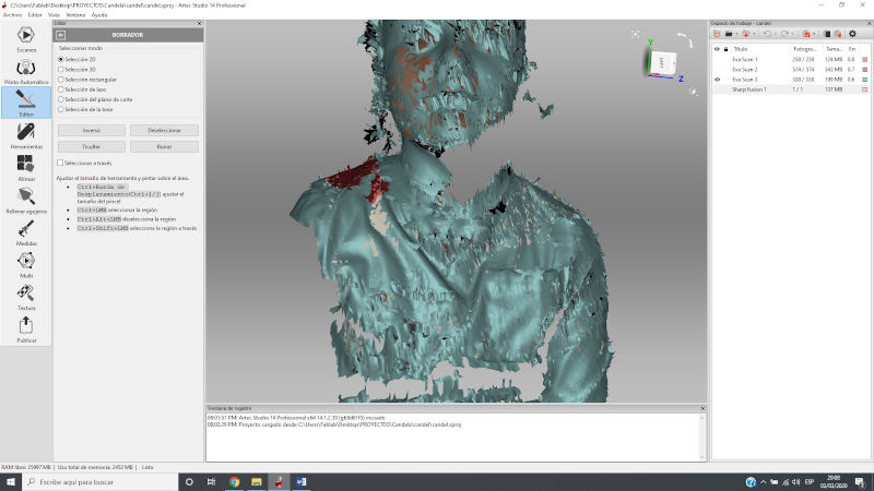
I remove the back of the chair that I don’t want to be part of the result.
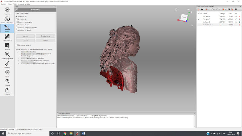
I merge the different shots with what I wanted to keep from them, with the “autopilot” option.
Then I cut the part I don’t want with “Eraser” tool.
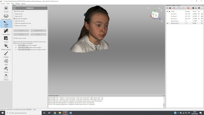
I continue the work closing gaps with the “fill holes” tool.
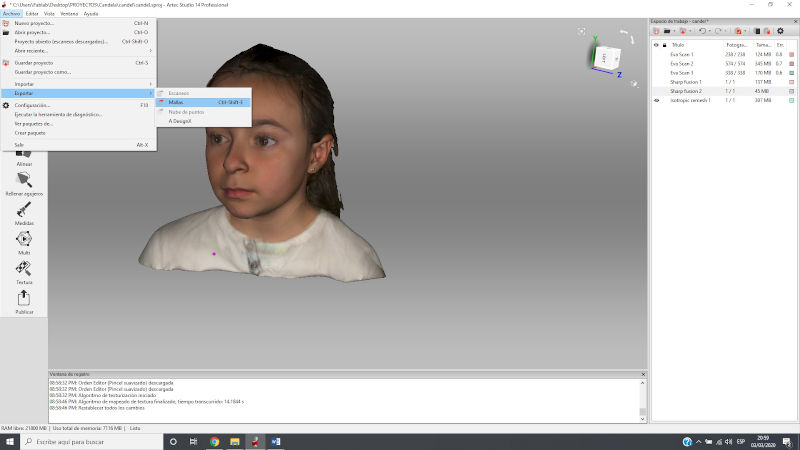
The mesh is exported as obj and stl.
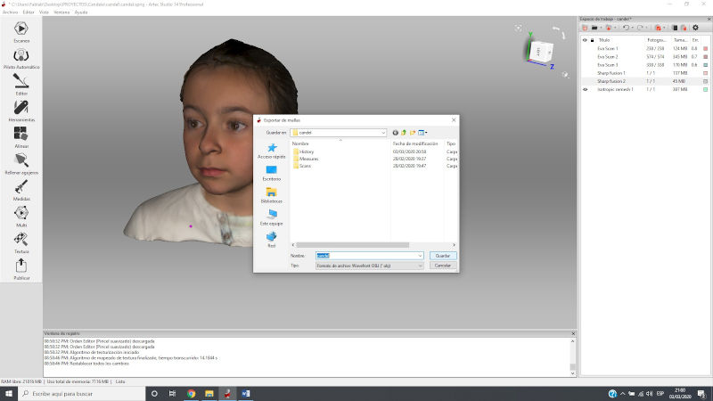
My mesh is ready to turn it into stl and be able to print it in 3D if it gives me time.
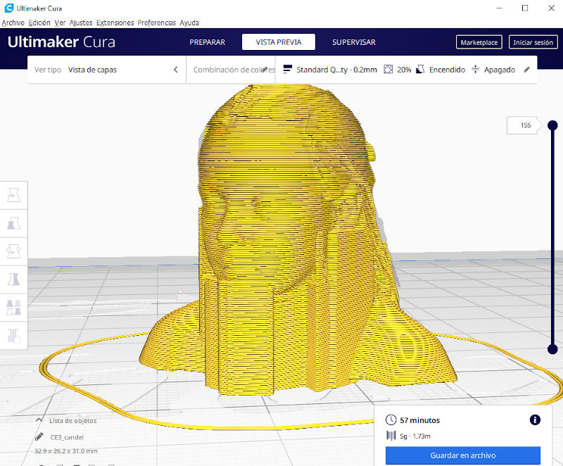
Finally I proceed to 3D print to Candela. I have used the Ender 3Pro printer.
For parameter configuration I use the Ultimaker Cura software.
This image shows the preview of the 3D printing process with FDM. The necessary material and the duration of printing are indicated.
After almost an hour, the 3D printing of Candela has remained that way.
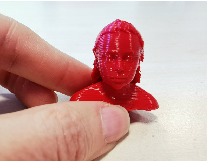
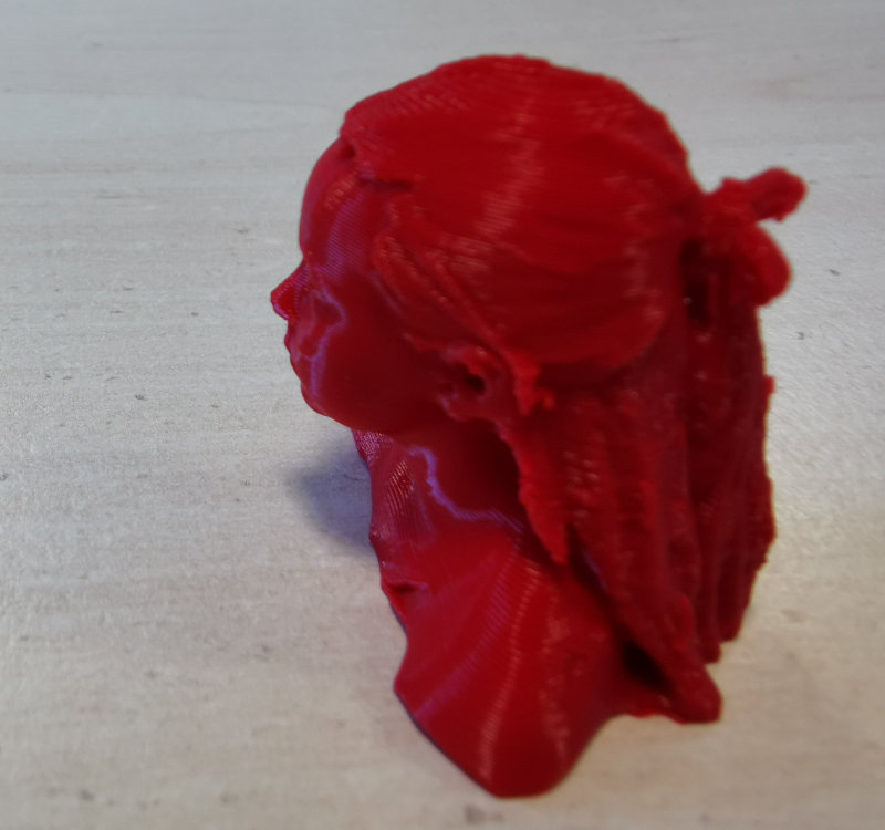
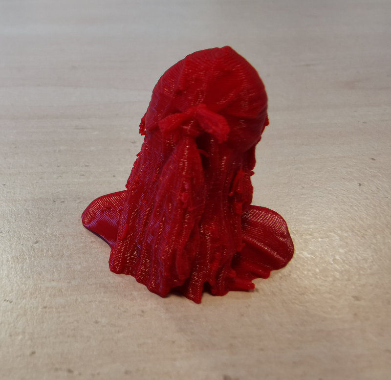
I think it has been very good and Candela will love it.
Tomorrow she will take her to school and explain to her friends how she made herself.
6.C. EXTRA ASSIGNMENT
The subject studied this week related to 3D printing and 3D scanning or three-dimensional scanning of objects is one of the fields in which I have developed my professional career for almost two decades now.
In the Research Support Service where I work (SEDIC) Industrial Design and Scientific Calculation Service, we acquired our first 3D printer in 2002, at first the researchers themselves were skeptical and did not believe much in the potential of this technology, but it was already as of 2010 when we took off and since then this service has not stopped growing, with the limitations of belonging to a small Polytechnic University.
That is why we would like to show some of the actions that we have been developing in relation to printing materials and prototype finishes.
6.C.1. Recycled materials for 3D Printing
The first 3D printing machine in the SEDIC is a Dimension bst 1200es, of FDM technology, and the material used is ABSplus.
This machine has a base where parts are printed that is disposable.
It is the disposable fungible base:
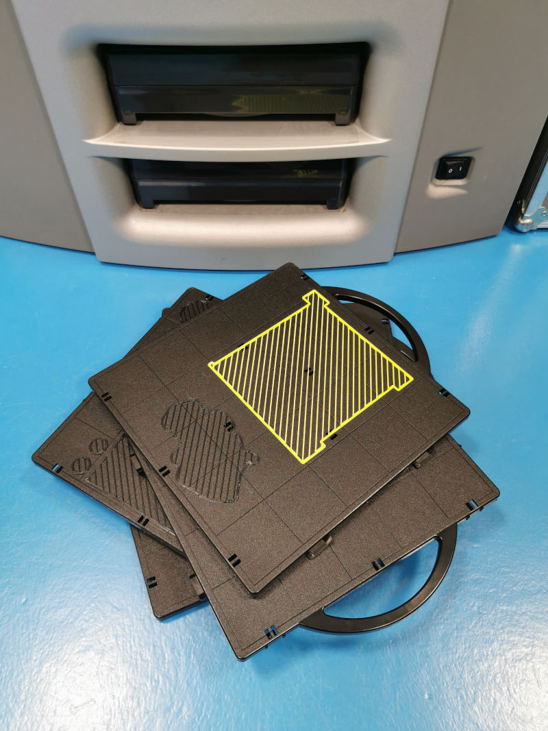
When buying the machine we did not know that the manufacturer was not responsible for removing this base or tray, they were times when sustainability was not taken into account.
But I thought it was a great waste not to reuse these bases and decided to do something with them.
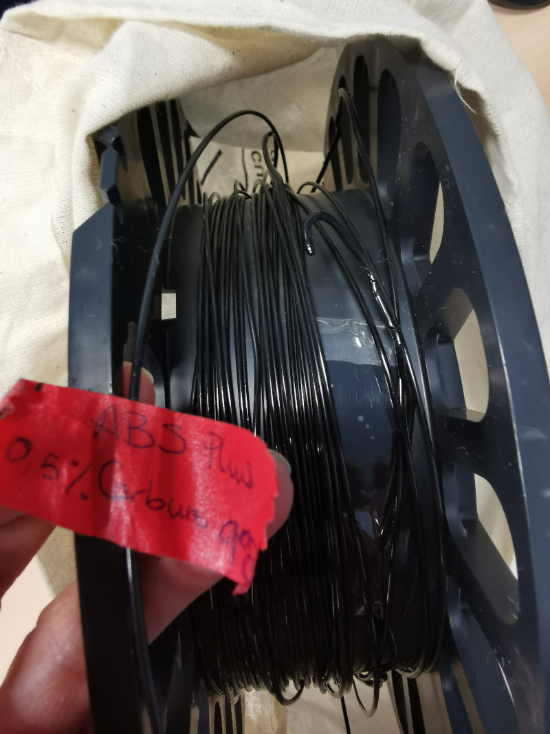
In our own laboratories I did material composition analysis and WOW !!
It is ABS similar to the filament used for printing.
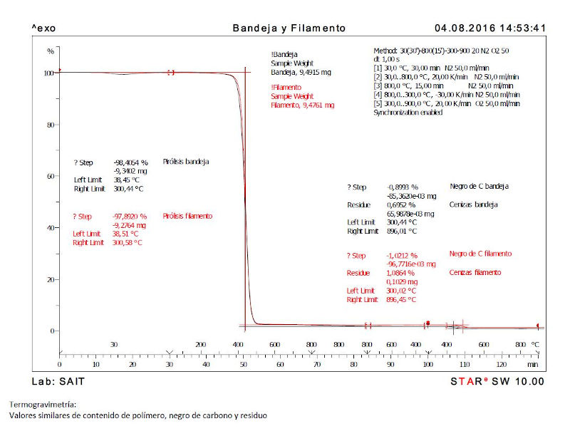
The red curve is that of the filament composition of the manufacturer who uses the printing machine, and the black curve is that of the composition of the disposable bases.
So I sent to crush the bases that I was storing for a long time so as not to throw them away with the rest of plastics.
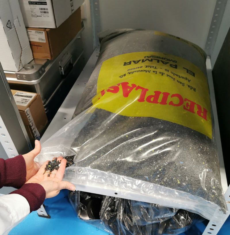
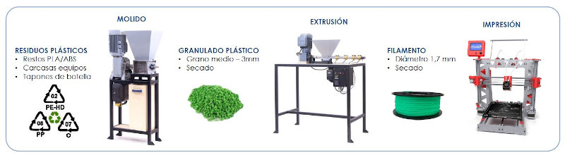
Now I am assembling my own plastic mill.
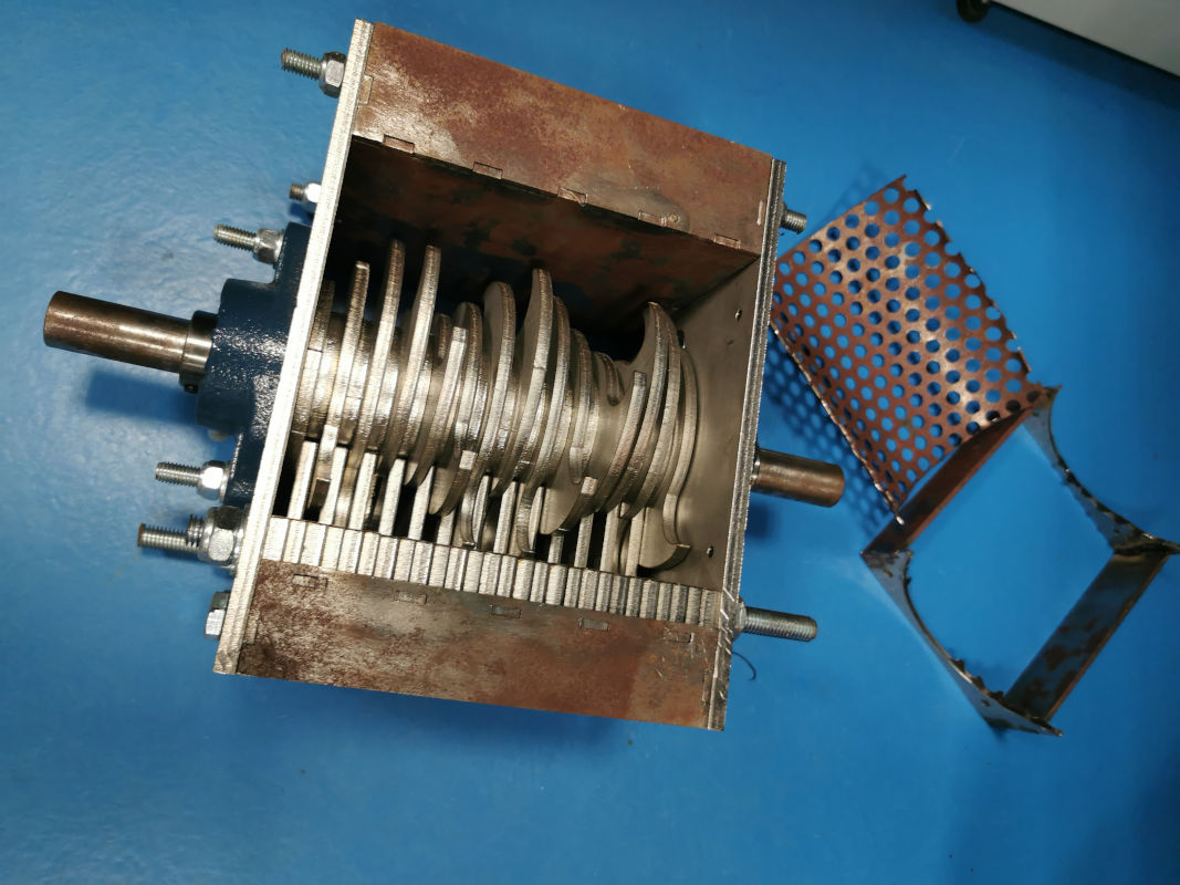
With an extruder and that crushed plastic we get our own filament.
NOTE
*As I mentioned before, the week of this assignment I had to participate in the random, and Neil asked me about the extruder. *
*I was very nervous, in addition to finding it difficult to understand and express myself in English and more under this tension, so I did not know how to explain my opinion about this machine very well. *
So I want to do it now.
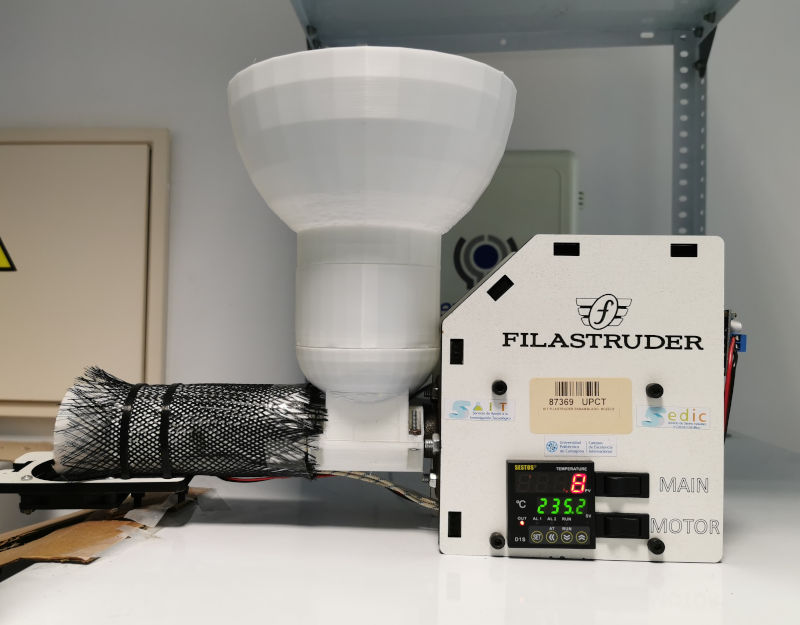
Filastruder is a small laboratory extruder to be able to extrude and obtain filament on a small scale. It is very practical, easy to use, does not weigh, does not need special or additional installations. The volume of plastic needed for filament production to start is approximately 50 grams of material.
That approximate value is the minimum, but you can obtain a much greater amount of filament that can be wound later and thus get our own coil of recycled material or from commercial pellets, both options, in which we have sometimes added additives.
In our laboratory, we do not need much more for the requirements that are presented to us. It is not an industrial extruder but it does its job very well in our Fablab.
We bought it directly from the United States in 2016 and it is currently more accessible and has a better price.
There was a before and after of Filastruder, having it allows us to carry out a lot of tests with different materials and additives in different proportions and with this we make composition and resistance studies of materials and allows us to know and characterize new plastics to use in 3D printing.
More information about this extruder can be found at this link.
We have also made a winding for the filament that comes out of the extruder.
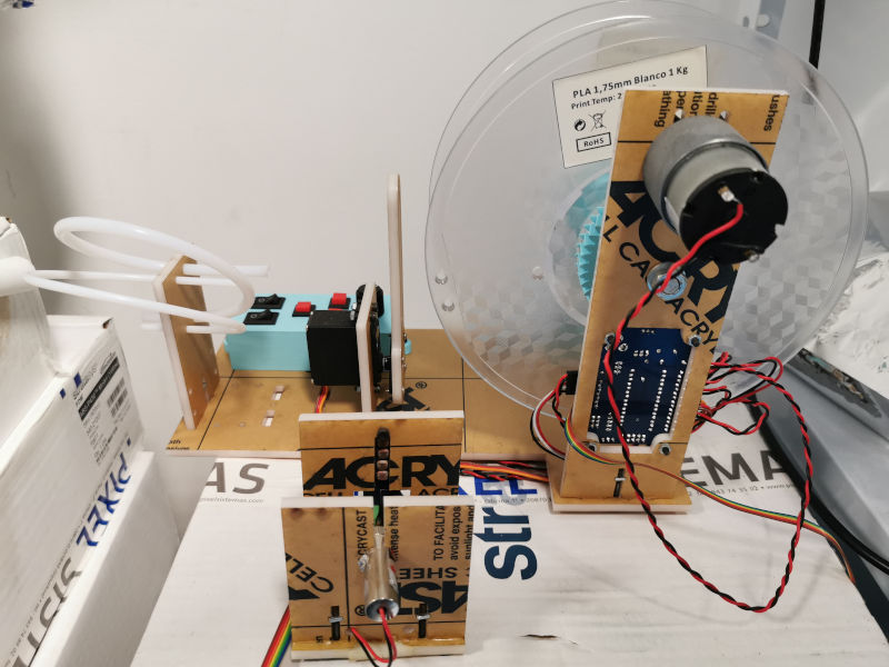
We use this recycled plastic filament in printers such as Prusa or Ender … and we get new models.

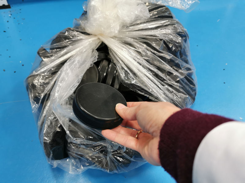
In addition to using these bases, we now recycle many types of plastic. In our laboratories there are containers that instead of throwing, we take advantage. Especially caps and containers.
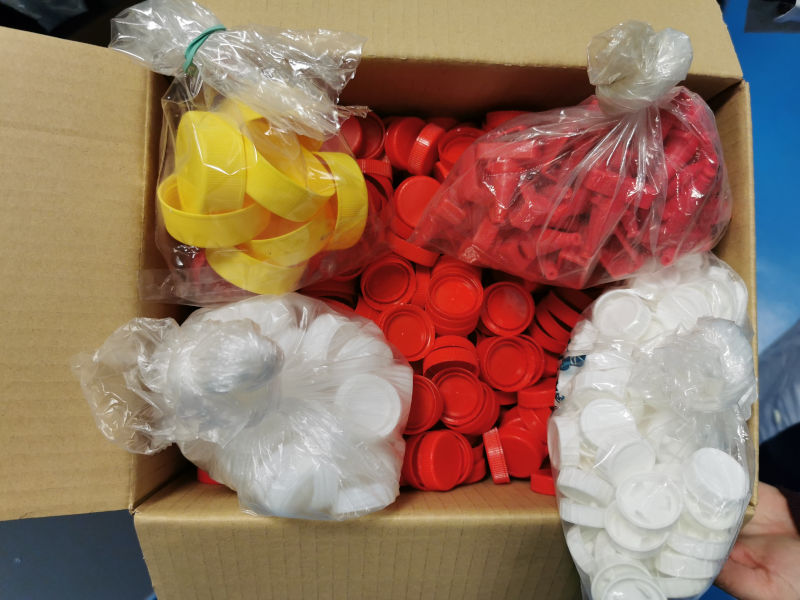
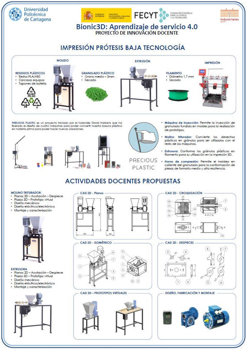
I am currently management a Final Degree Project to a student and we are creating a structure that integrates the entire recycling process, in which the plastic grinder mill takes the pellet to the extruder hopper and passes the filament to the extruder. overwhelming and we have our filament to place in the 3D printer. It will include safety measures so that the mill does not start up if it is not completely safe.
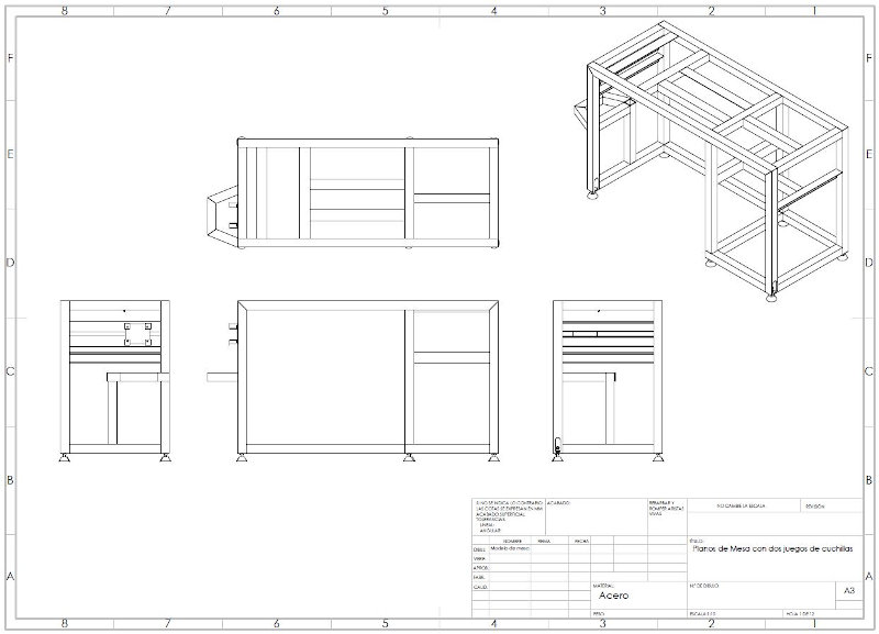
This is a diagram of the structure assembly that will integrate the plastic crushing mill, the extruder, the winding machine and all the accessories.
This Final Degree Project is framed within a Teaching Innovation Project, which aims to integrate the concept of the ODS objectives (Sustainable Development Goals) based on finding a sustainable way to manufacture prostheses, thus also doing social work.
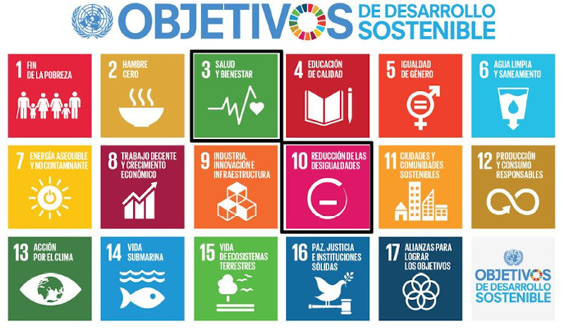
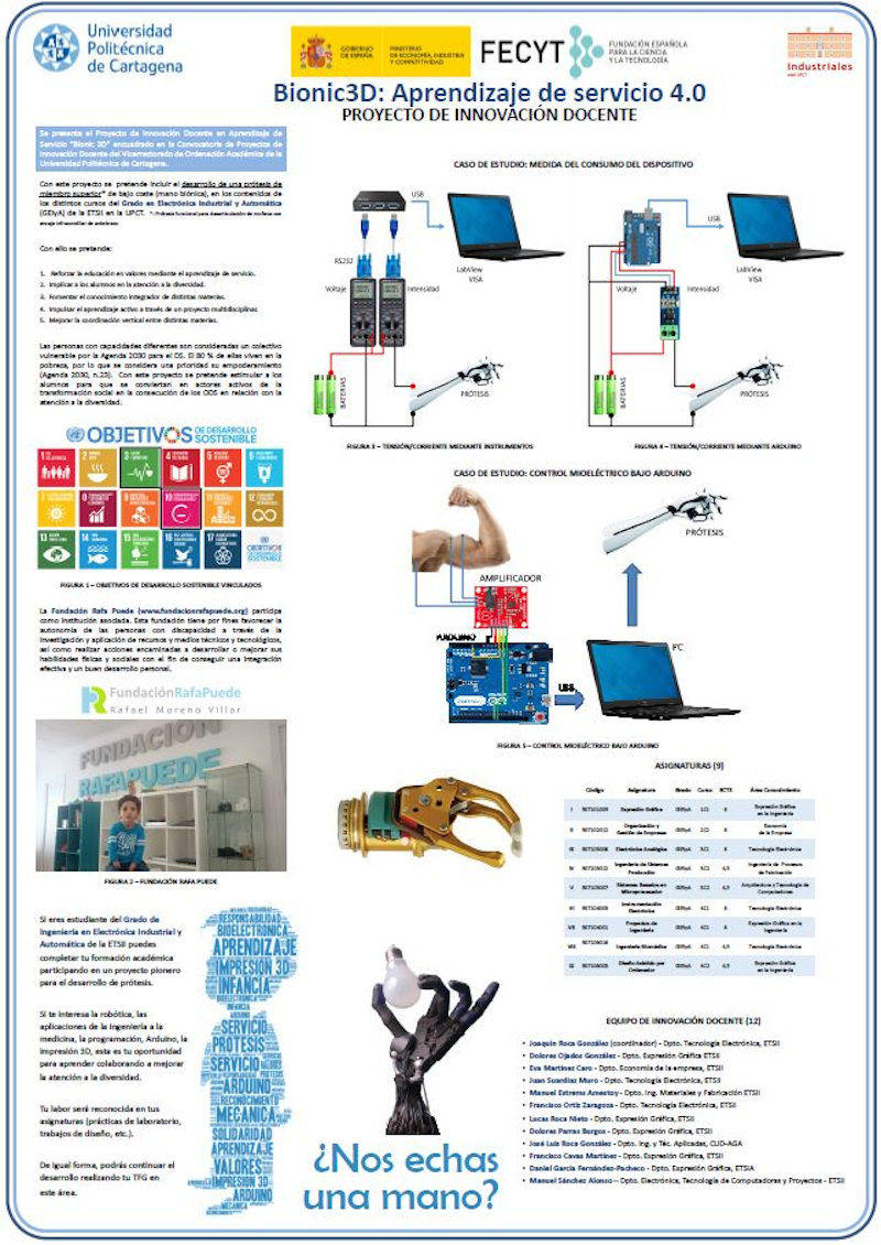
This is the part of the complete Teaching Innovation project that is being addressed in the Final Degree Project that I am currently leading.
On previous occasions other works have been to develop prostheses, especially for upper limbs, and mostly children.
These low-cost prostheses with recycled materials have allowed children to have a “hand” with which they were not afraid to play on the beach or do acrtivities that could damage the prosthesis. In most cases, they did not dare to carry out certain activities with their sophisticated prostheses of noble and expensive materials if they had one.
In this way, they have prostheses of their favorite superheroes that if broken can be fixed or reprinted.
In the attached image you can see one of the projects, led by me, developed in this line in which students of Engineering Degree are involved.
6.C.2. Additive materials for 3D printing
In this field, we have carried out different studies to obtain our own additive material and to compare the results of these additives to the common 3D printing materials that are usually thermoplastic.
About five or six years ago I began to carry out research work to verify that this recycled plastic (ABS at first) and the models created with this material are of quality.
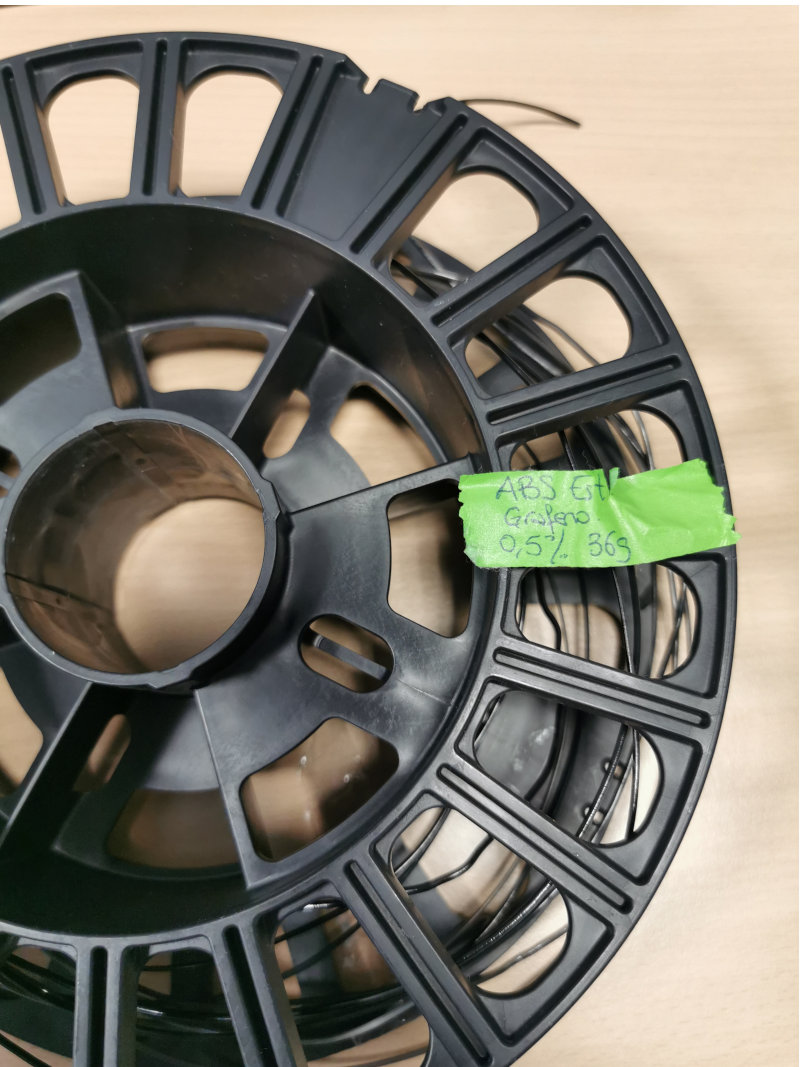
This results in another Final Degree Project directed by me in 2017 that studies the characteristics of this recycled plastic and additive with nanomaterials such as Graphene or Silicon Carbide.
STUDY OF THE IMPROVEMENT OF ABS PROPERTIES THROUGH THE ADDITION OF DIFFERENT NANOMATERIALS. RECYCLING AND REVALUATION
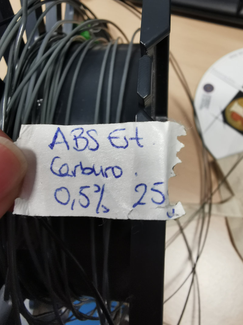
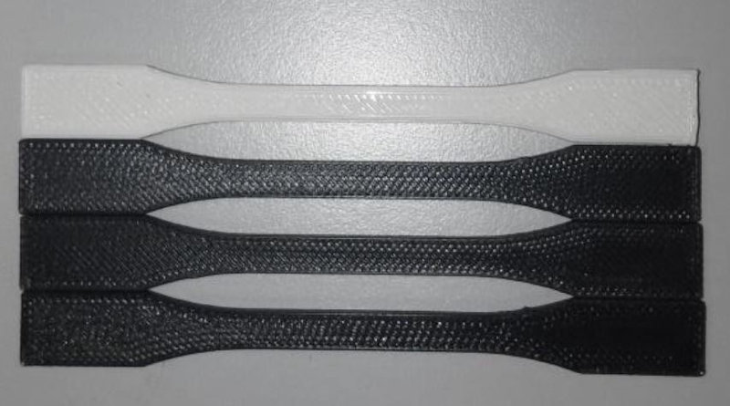
The trials of this study were performed on these patterns:
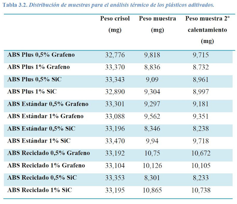
These are examples of the filaments obtained used to print 3D specimens subjected to tensile / traction, impact and hardness tests.
Some of the mechanical traction specimens tested::
These are the results and conclusions of this work:
Results:
The results obtained determine that the ABS can be recycled and reused, since very similar values have been obtained in the mechanical tests between commercial plastics (ABS Plus and Standard ABS) and the recycled ABS.
In addition, these values indicate that the recycling method used is appropriate, since what has been done has been to extrude the crushed plastic and reuse it, which does not affect the properties of the plastic and allows a new use to be established for material that has already fulfilled the function for which it had been designed.
This result can be very positive, as it helps not to pollute the environment, which is a great sustainability objective.
Conclusions:
It has been shown that an engineering plastic such as ABS, which has great properties on its own, can be even better with the addition of small amounts of nanomaterial, in this case, graphene or silicon carbide, which can place it as one of the best engineering plastics that currently exist, being able to meet the needs of very specific applications.
It has been concluded that the use of high-tech mechanisms is necessary to achieve good results in this area.
A new use for ABS has been determined, being able to be recycled and reused for other possible applications while maintaining their properties and even improving them, with the addition of nanomaterials.
Taking into account the amount of plastic that is produced daily on the planet, and the large amount that is disposed of polluting the environment, finding ways to recycle plastics to give them a new use is always a great find.
Future Research Lines:
This work may be the beginning of great discoveries, as there are possible future lines of research, such as:
-
Determine how much nanomaterial must be added to a plastic so that it starts to be a conductor of electricity.
-
Analyze at a chemical level the link that occurs between the polymer chains and the nanomaterial.
-
Optimize extrusion and printing techniques.
-
Carry out these tests with other materials such as PLA.
-
Deepen the study of 3D printing methods and geometries and positions of the models to be printed.
The drama was, that in less than a year after finishing the TFG this student died of sudden death, very young and everyone who worked with her was shocked.
It was terrible.
We continue to recycle plastic materials and perform tests, but we have not raised a study like this. Very recently, the mother of this girl called us to ask us to disclose and continue her work and now we have resumed it.
Other works related to 3D printing developed in the SEDIC and directed by me, have to do with the use of geometries obtained by 3D printing used as noise level reducers. As an example I refer to these two works that may be of interest:
NOISE ATTENTION USING 3D PRINTING METHODOLOGIES Link to document
ADDITIVE MANUFACTURING AND NOISE ATTENUATION IN OFFICE WORK Link to document
6.C.3. Surface finish of 3D printed parts
In this section I want to show some of the surface finishes that we apply to 3D printed parts and objects.
Sometimes we use products that reduce the stratification of material deposition layers.
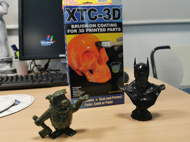
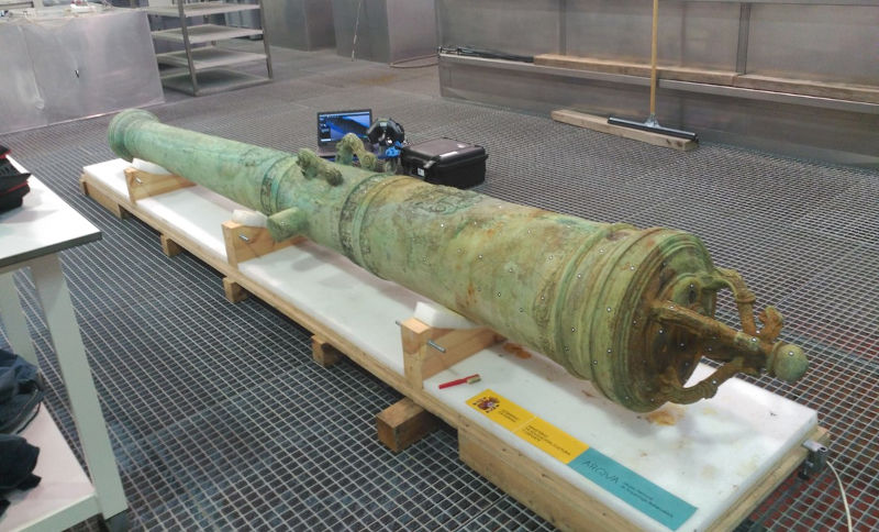
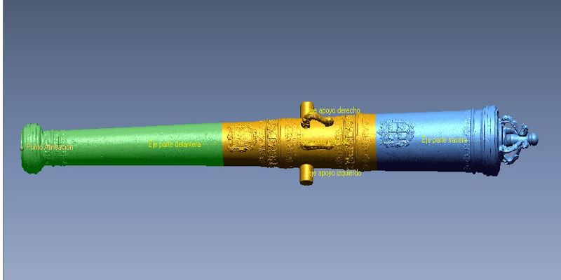
Other times we apply products and paints that simulate the material that the object originally had when it came from 3D scanning.
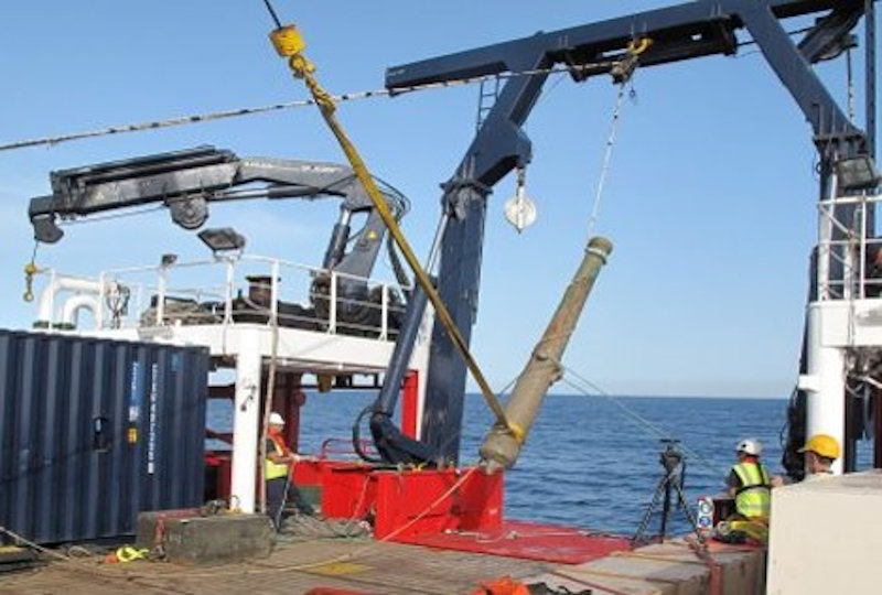
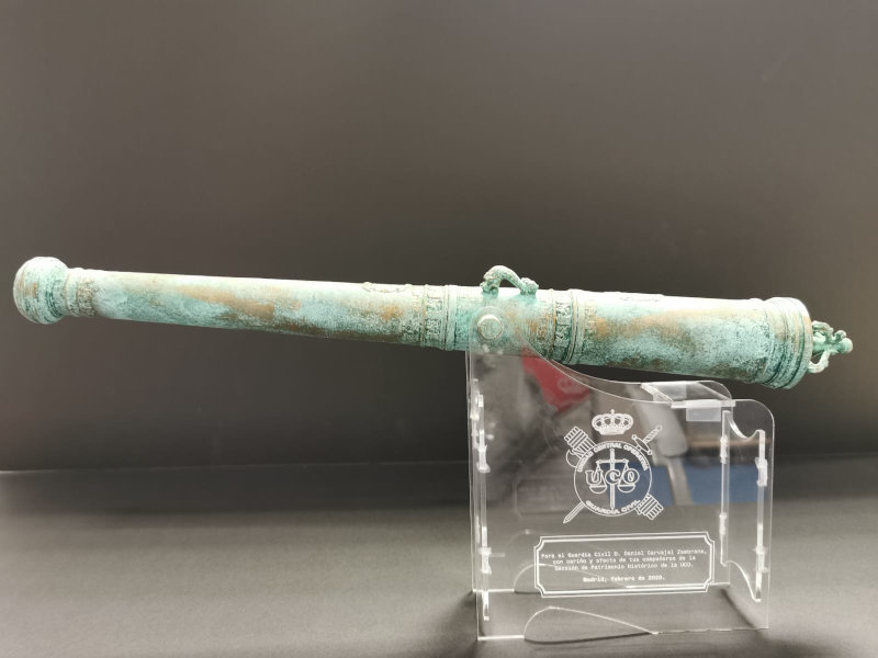
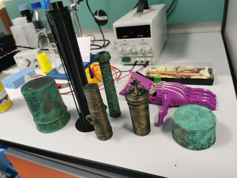
As is the case with these canyons rescued from the sea. From a sunken frigate called “Our Lady of the Mercedes” that carried within it a real treasure that Spain had to litigate with the treasure hunter company “Odisey” and won.
This treasure of gold and silver coins and valuable objects is now in the national museum of underwater archeology that is in our city, Cartagena.
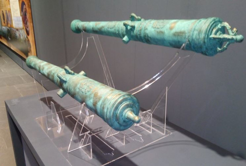
These are the two guns exposed in the museum at 1/2 size (approximately 2.5m in length)
This is one of the canyons scaled to 50cm in length.
And this is a small replica of about 15cm in length and with another finish.
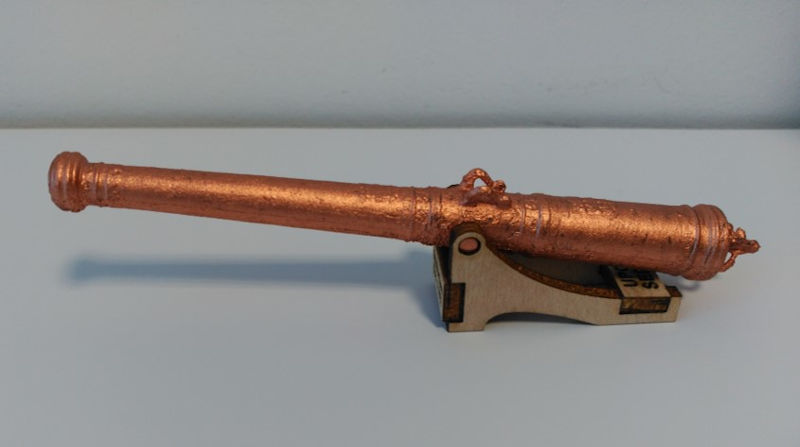
All these replicas of the barrels are supported on supports designed in our Fablab, made of methacrylate or wood, cut and engraved in the laser cutter and assembled so that the barrels are held in a suitable position to be able to expose them without causing them to lose prominence.
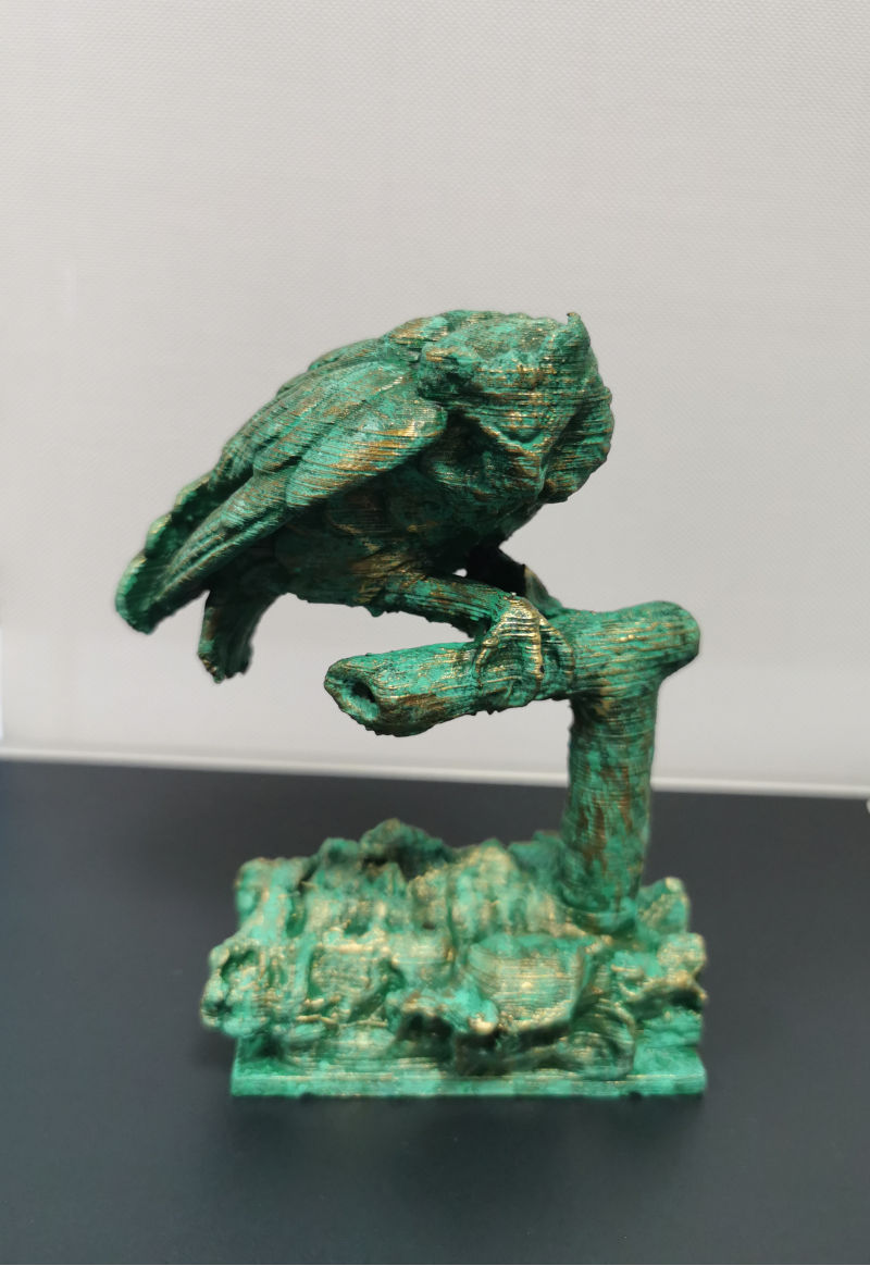
This other figure comes from a sculpture and its replicas were the trophies for the winners of a painting contest. We had to change the angle of position of the trunk to change the center of gravity of the set and that the bird did not fall forward due to its own weight.
This other image is from a sculpture of Holy Week in our city.
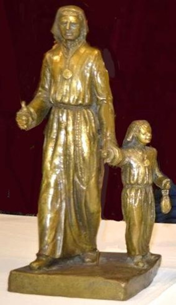
It’s about casting imagination and looking for options so that the objects are as we have imagined or as they really are. We are always doing tests …
Sometimes we like the result and other times, not so much …
6.C.4. 3D scanning applications
I find it interesting to tell some of the applications we give to 3D scanning.
Calculation of dimensions, volumes and densities.
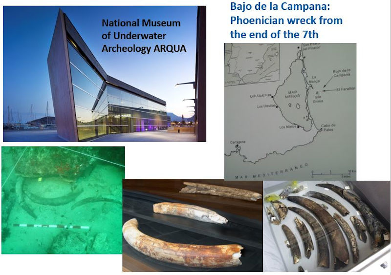
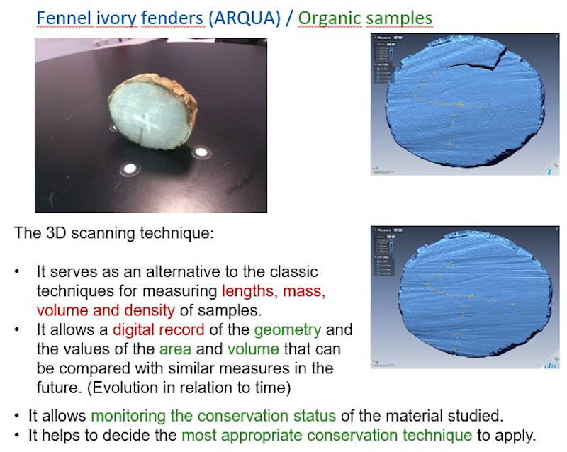
Elemplo 01: Scanning of elephant ivory fangs from an underwater wreck
The volume and density of small pieces were calculated and this helped specialists decide which was the best conservation method applicable.
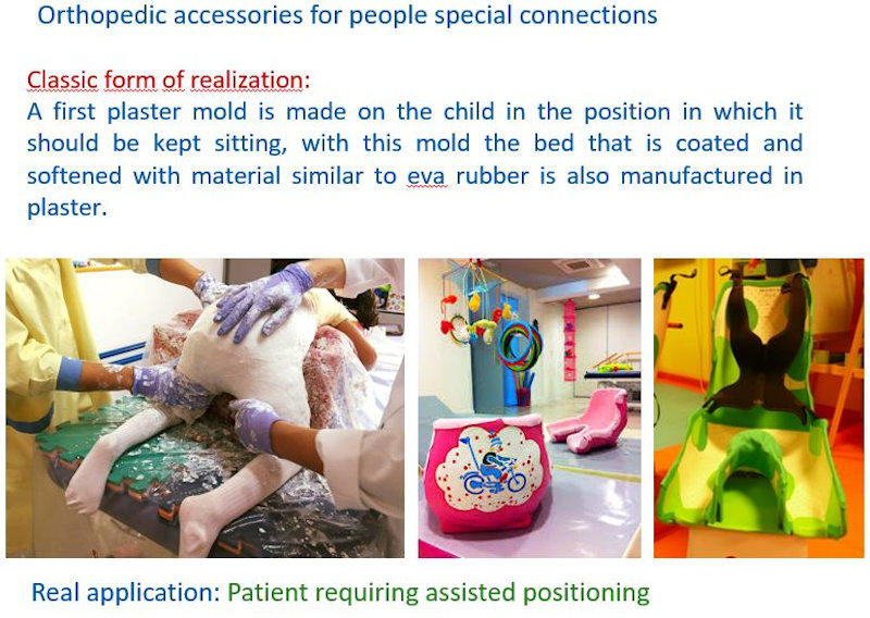
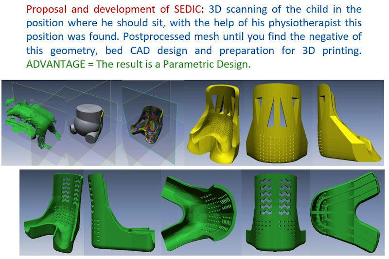
Elemplo 02: Scanning of patients who have to make a custom orthopedic accessory
I could show more examples that I find interesting, but many jobs that require us require confidentiality and on the other hand, I would never finish documenting this assignment.