9. EMBEDDED PROGRAMMING
This week I worked on
Individual assignment:
- Read a microcontroller data sheet.
- Program mi board to do something, with as many different programming languages.
- Pogramming environments as possible.
Group assignment:
- Compare the performance and development workflows for other architectures.
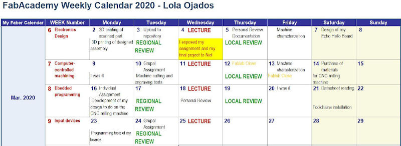
I have continued using my weekly planning in which I have updated my activity in FabAcademy
This week is being especially tough.
In Spain we are in a state of alarm, we all collaborate to reduce the number of coronavirus infections, which is affecting practically every country in the world.
The Fablab remains closed and I have almost no material at home, but above all, I do not have the machines with which to complete my assignment.
From the SEDIC research support service that I run at the university where I work, we are working on several 3D printing projects for medical equipment, we collaborate with a working group in search of a ventilator design for patients who need it , looking for ways to reduce the disinfection time of ambulances and more initiatives in the fight against the coronavirus. I am dedicating a lot of time to it, together to start teleworking for people who work with me and have never done it.
Also, my children are at home without going to school and I assume the functions of teacher of their subjects, and of their extracurricular activities, music, languages, instruments …
A real madness!

In this situation everything is upside down, head down …
And this image in which the text “life goes around many times” appears gives a little illustration of how we are these days.
*Reminds me of the design I made in the week 6 assignment of a bird in a cage, now we humans are being “caged” by an unknown external threat to our generation. *
Within all this chaos.
I’m going to try to document what I’ve accomplished this week from the proposed assignments.
9.A. GROUP ASSIGNMENT
As in previous assignmemts, this week I made the group assignment with my co-worker Álvaro Macián, we are both from Sedicupct-Fablab and our local Fabacademy node is FabLab León.
The Group Assignment page is at the following link.
This is the second week that our FABLAB remains closed due to the coronavirus pandemic.
We work from home and communicate by videoconference whenever the network allows us, at the moment there is a lot of data traffic and sometimes it collapses.
It is difficult because we have limitations of everything, materials, machines, communication …
But right now the best we can do to help stop the infections is “Stay home.”
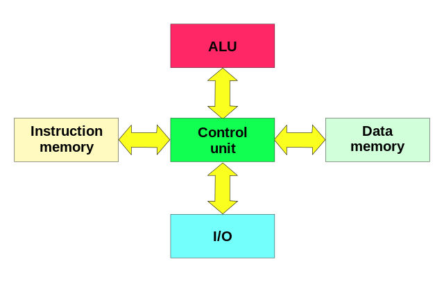
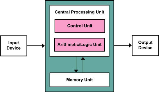
In this link, we found a description of the types of microcontroller architecture that exist.
Some types of microcontroller/processor architectures:
-
Harvard Architecture:
- Texas Instruments TMS320 C55x processors.
- The AVR microcontrollers from AVR from Atmel Corp and the PIC from Microchip Technology, Inc ..
- Von Neumann architecture:
-
ARM architecture:

- ARM microcontrollers family.
- Raspberry Pi boards, STM32 microcontroller,…
-
RISC achitecture:
In computational architecture, RISC (from English Reduced Instruction Set Computer, in Spanish Computer with Reduced Instruction Set) is a type of CPU design generally used in microprocessors or microcontrollers with the following fundamental characteristics:
- Fixed-size instructions presented in a small number of formats. - Only the loading and storage instructions access the data memory.
9.A.1. Workflows for AVR microcontrollers (Harvard Architecture)
9.A.1.1. Development environment for AVR.
Setup for all of your AVR programming
These steps will only have to be done the first time to configure our USBtinyISP programmer and toolchain.
Summary:
-
Install Git
-
Install the Atmel GNU Toolchain
-
Install GNU Make
GNU Make is a tool which controls the generation of executables and other non-source files of a program from the program’s source files.
-
Install avrdude
AVRDUDE (software for programming Atmel AVR Microcontrollers)
-
Update your PATH
We need to tell Windows where to locate all of the tools you’ve just installed when you type their names on the command line.
Start menu > Control Panel > System > “Advanced System Settings” > “Environment Variables” >”Path” > “New”
The three values to add are:
C:\Program Files\avr8-gnu-toolchain\bin
C:\Program Files (x86)\GnuWin32\bin
C:\Program Files\avrdude
-
Install Drivers for your Programmer
The USBtiny programmers use a generic libusb driver, but Windows 10’s driver signing policy makes the installation more complicated. Fortunately, there’s a tool that helps with this. Download Zadig and launch it. Plug in your programmer, and select the “USBtinySPI” device in the list. (If it doesn’t show up, go to the Options menu and click “List All Devices”. The driver you want to install (to the right of the green arrow) is either libusb-win32 or libusb0. Click the “Install Driver” button. You should only have to do this once.
-
Sanity Check
In Git Bash:
make –v

avr-gcc –version
Connect your programmer to a USB port
avrdude -c usbtiny -p t45
9.A.1.2. Set the programmer ATtiny45
-
Get and Build the Firmware AVR.
Download and extract the firmware source code
In GitBash: cd (source code directory)
makeThis will build the hex file (fts_firmware.hex) that will get programmed onto the ATtiny45.
-
Program the ATtiny45
Edit the file called Makefile with WordPad.
Near the top of the file, find the line that says:
PROGRAMMER ?= **usbtiny**and change usbtiny to whatever programmer you’re using:
-
Small translucent blue programmer: avrisp2
-
Large translucent blue programmer: jtag2isp
-
White box with blue stripe: atmelice_isp
-
Any fabbed board with an ATtiny on it: usbtiny
-
Plug the board into a USB port. In GitBash:
make flash
This will erase the target chip, and program its flash memory with the contents of the .hex file you built before.
make fuses
This will let the chip use the reset pin to program other boards, but will disable the ability for this chip to be programmed again.
- Blow the Reset Fuse
9.A.2. Programm an AVR board using the USBtiny
Use the programmer with a hello board using the Arduino IDE. To do this, load the libraries for attiny programmers.
http://fabacademy.org/2019/docs/FabAcademy-Tutorials/week08_embedded_programming/attiny_arduino.html
9.A.3. Workflows for ESP32 microcontrollers (Xtensa LX6 Architecture)
To program this board we can use the Espessif tools or using the Arduino IDE.
9.A.3.1. Espressif IoT Development Framework (IDF)
This link explains the steps to configure the programming environment.
In Windows:
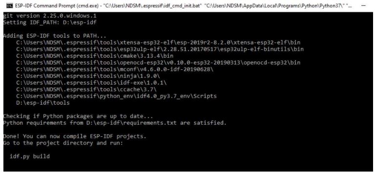
- Install toochain
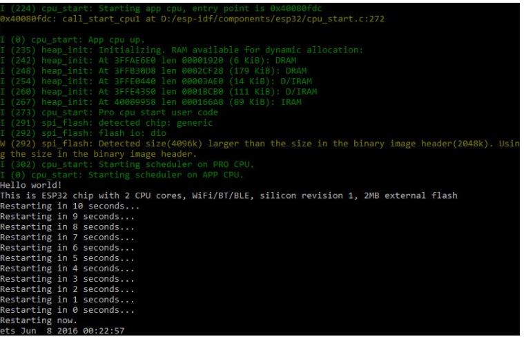
At the end of the installation the console opens and this appears:
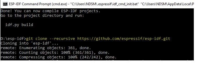
- Clone libraries
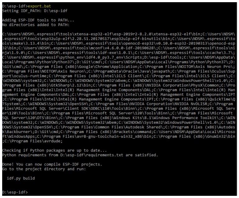
- Set up the environment variables
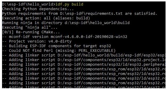
- Build a project. Build the hello-world example from the libraries.
Type “cd hello-world” and then:
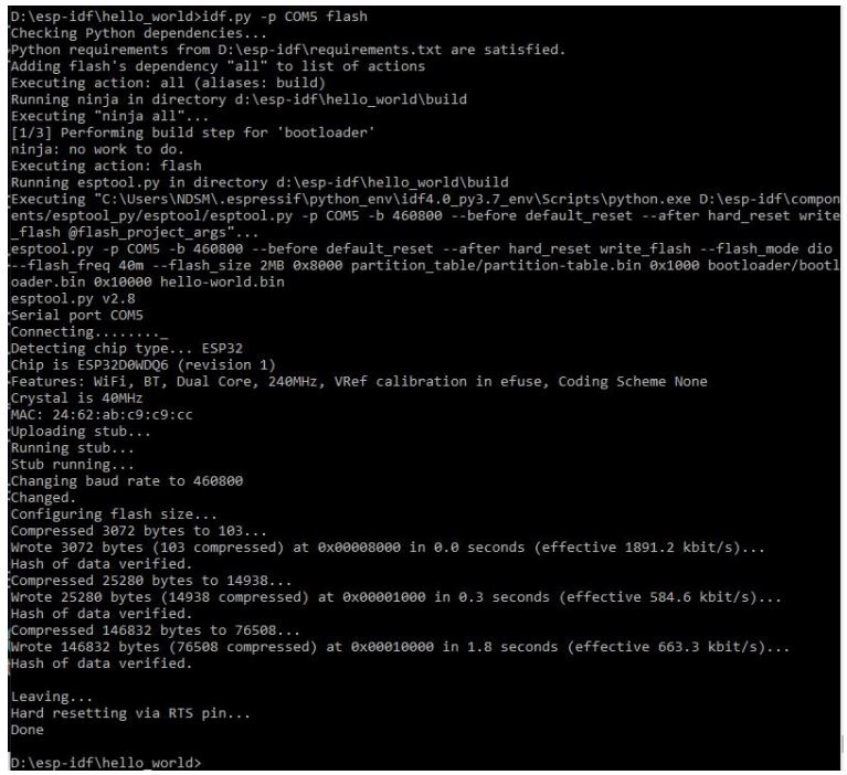
- Flash onto the Device
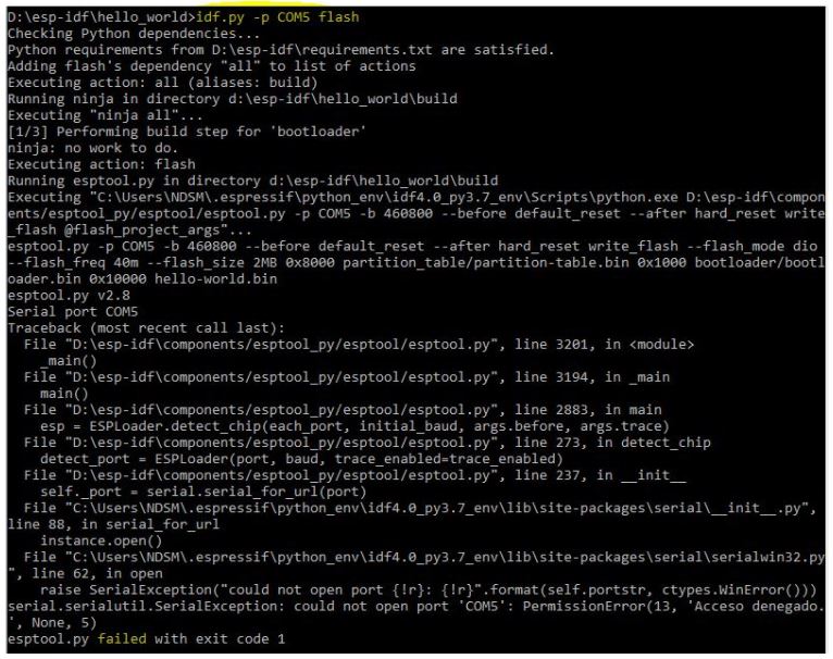
Error!!! I have to push the RST buttom and then type it again.
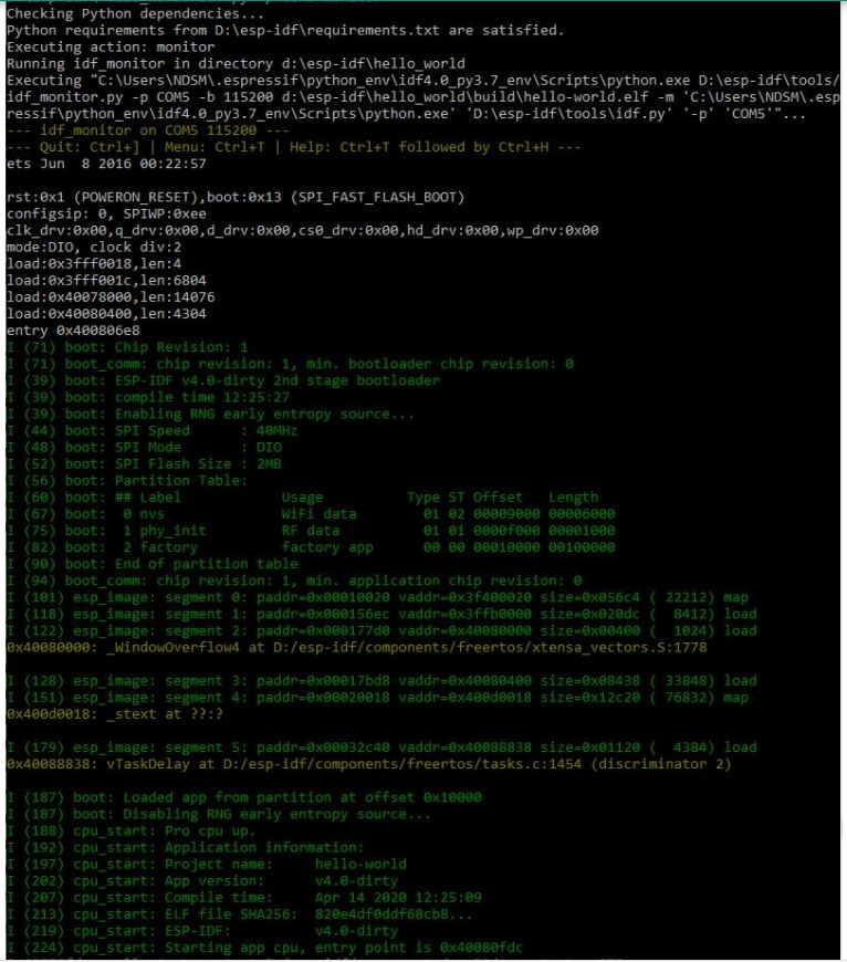
- Open the IDF Monitor to check if “hello_world” is indeed running.

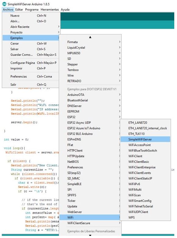
9.A.3.2. Arduino IDE
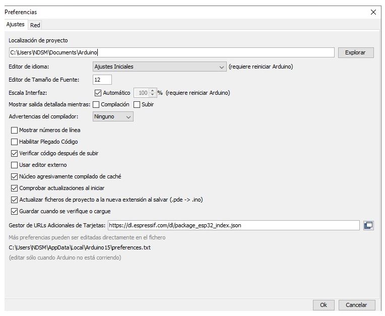
- In “Preferences” paste the URL to get the esp board
https://dl.espressif.com/dl/package_esp32_index.json
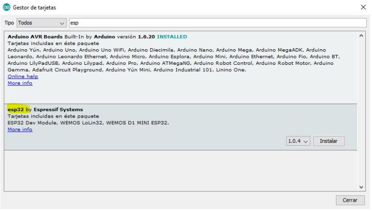
- In “Board management” install “esp32”
- Select the board “DOIT ESP32 DEVKIT V1”
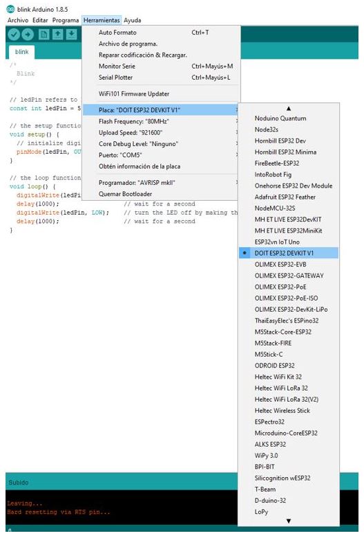
There are many examples to learn how to program it.
9.A.4. Workflows for ARM microcontrollers (ARM Architecture)
ARM is 32 bit Instruction set (CPU) Architecture or Microprocessor while AVR is family of microcontroller.
ARM can be both used as Microcontroller or as Microprocessor (Coretx M series or Cortex A series) while AVR used only as Microcontroller.
ARM has high Processing power as Compare to AVR.
Any OS can be installed on ARM based machine but no such facility in AVR.
More memory in ARM while less RAM/ROM Used in AVR.
ARM is mostly 32 bit while Avr comes in 8/16/32 bit variant.
ARM is High speed and Costly while AVR is cheap and effective.
The toolchains for the ARM family are practically the same as for the AVR family.
We currently don’t have access to the fablab so I won’t be able to test it.
9.B. INDIVIDUAL ASSIGNMENT
- Read a microcontroller data sheet.
- Program mi board to do something, with as many different programming languages.
- Pogramming environments as possible.
9.B.1. ATtiny 44 DataSheet
To carry out this individual assignment I am going to use the “Hello Board” that I have designed and manufactured for the week 7 assignment.
This board has an ATtiny44 microcontroller, and its datasheet can be found at this link.
This is what the ATtiny 44 microprocessor datasheet looks like that is built into my “Hello Board”:
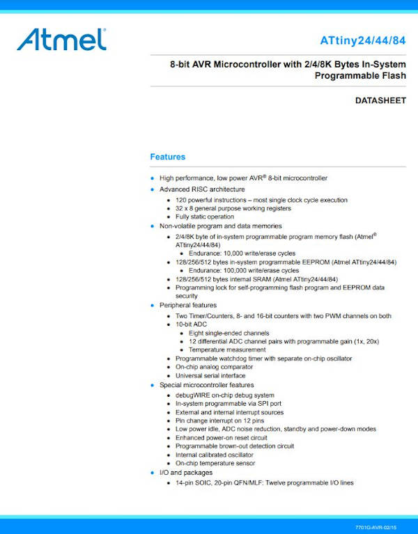
The first time you are faced with reading a data sheet of a processor like the ATtiny44, you feel a bit lost because it is difficult to understand, but by breaking down the information it includes, you can get to extract the necessary to run the project that we have considered.
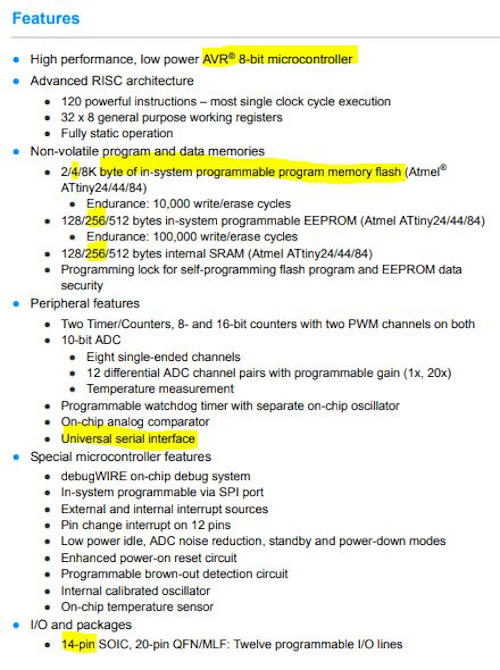
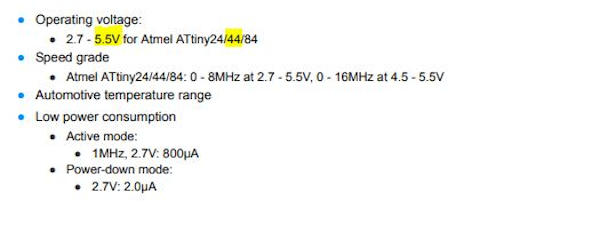
The first thing I find on the data sheet are the characteristics of the microprocessor, which I think can help me, I have underlined them in yellow.
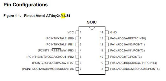
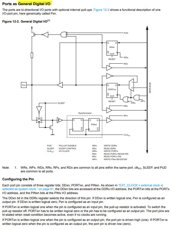
In the datasheet, the microcontroller’s pin configuration and its distribution appear where the function of each pin is indicated. This information is necessary and very useful to be able to design and program a board.
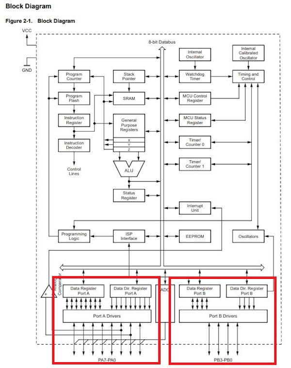
In this other graph of the Block Diagram I can see the structure of the elements that make up the programmer.
For me, it is quite difficult to understand. I distinguish that there are 2 separate ports for inputs and outputs with their respective pins. Each port will have different functions and characteristics.
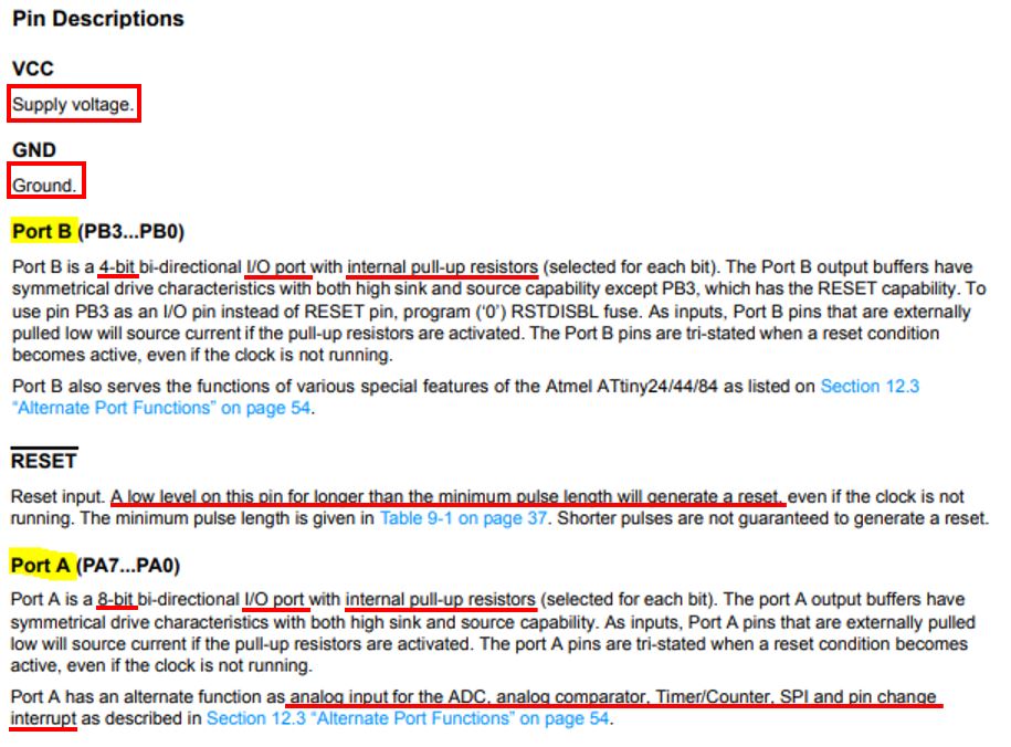
In the Pin Description section, the differences between these two ports and the RESET function are explained.
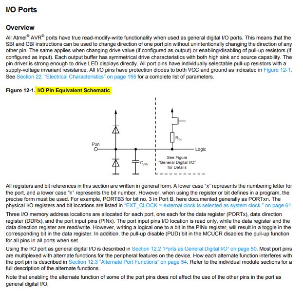
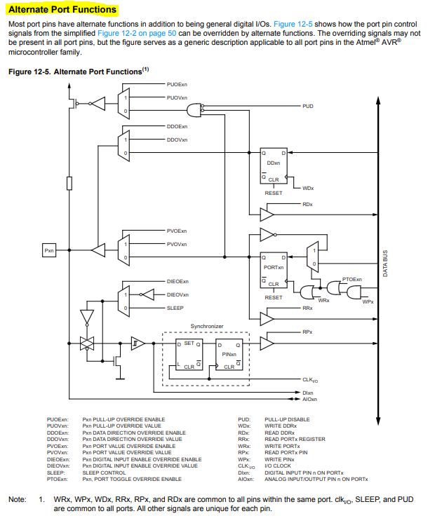
In another of the sections, referring to input and output ports, I have been able to read and find out about the characteristics of these ports and also about their general functions and alternative functions.
Actually the data sheet of a microcontroller like this that I am studying, the ATtiny44, is a complex but very complete document with information of all kinds about the configuration, distribution, functions, ports, the elements that compose it. ..
In this specific case of the ATtiny44, its datasheet has 196 pages.
Therefore, from these main data that I have managed to understand and distinguish and with which I can begin to work to design and manufacture a board with an identified function using this microcontroller, you can deepen everything you need by consulting the different sections of the data sheet for each question or query that needs to be made.
9.B.2. Programming my board
I am going to program my Hello Board which has an ATtiny44 microprocessor built in using the UsbTinyISP programmer, which I made previously in the week 5 assignment.
9.B.2.1. Toolchain installation
First, I have checked if I have the toolchains installed on my computer. And I don’t have them, since I did the electronics productions practice on the FABLAB computer that is there and I don’t have access.
So I had to go through the same steps as in section 5.B.2 of the week 5 assignment, but this time on my personal laptop, which is the one I can now work with from home.
To do this, I first set up the environment by following this tutorial for Windows. (Image of the tutorial is displayed when accessing it).
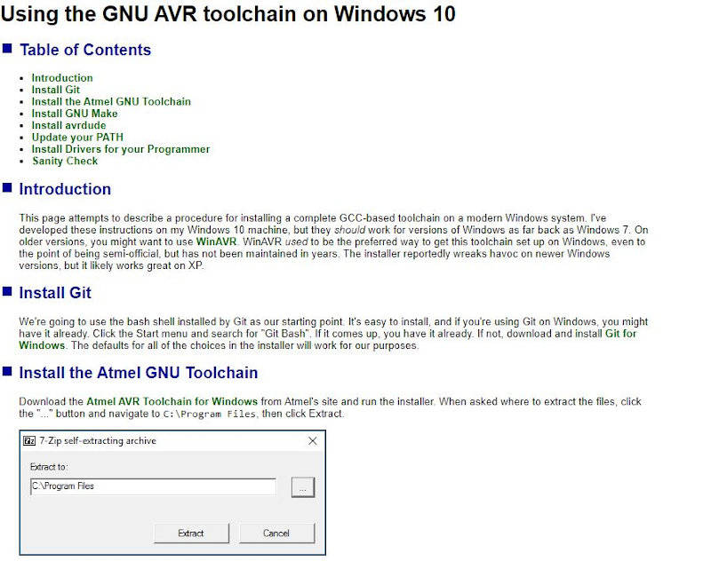
And the steps followed were these:
-
Download Avr Toolchain for Windows
-
Download GNU Make
-
Download avrdude
-
Download Zadig
I had a “Problem!” When editing the path make sure the path is correct. The tutorial indicated:
C: \ Program Files \ avr8-gnu-toolchain \ bin
But in my case I had to put:
C: \ Program Files \ avr8-gnu-toolchain-win32_x86 \ bin
And if it doesn’t, close Git Bash and reopen it and perfect.
9.B.2.2. Prepaning ARDUINO IDE to programming
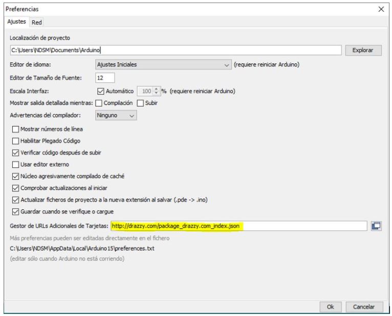
First you have to tell the Arduino IDE the URL where to find the package to work with the Attiny boards.
From File> Preferences
You have to paste the text: http://drazzy.com/package_drazzy.com_index.json
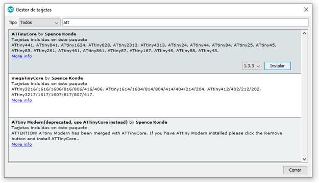
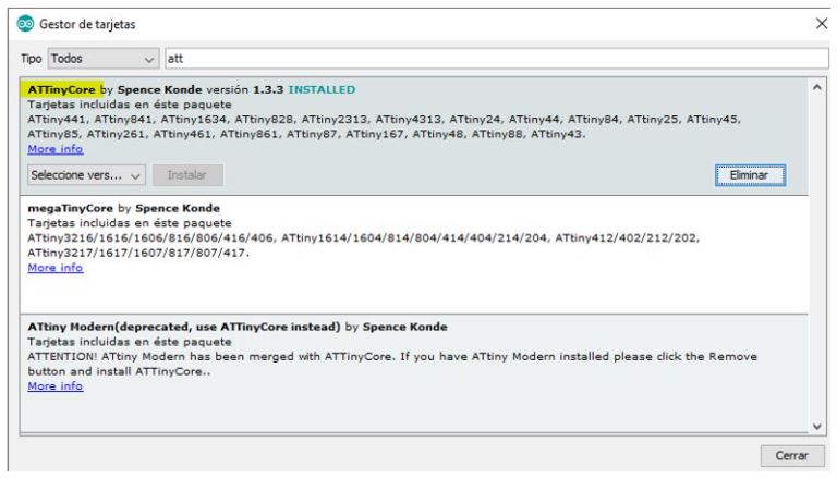
Then go to Tools> Board> Board manager
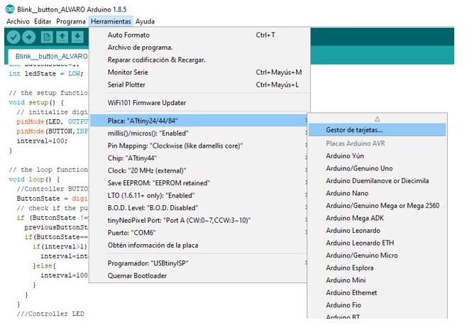
Find ATTinyCore package and install.
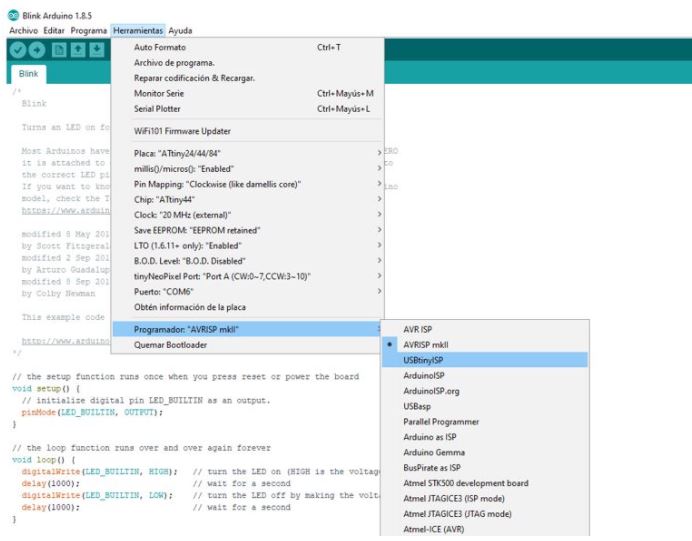
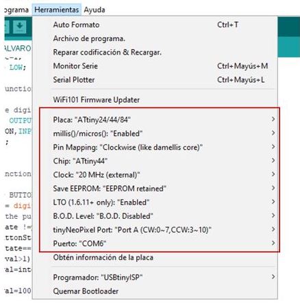
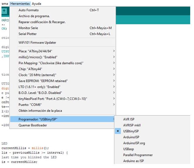
Now we select the parameters of our board in Tools:
Now set the fusible bits of the microcontroller. Click Burn Bootloader.
Note: This step is important if you need to set the clock. I still don’t know what my programming will be, but it is better to leave this set so that the clock works correctly in case of using it.
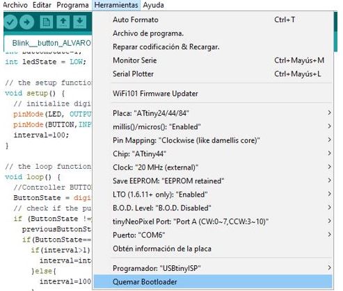
Select the programmer that we are going to use, USBtinyISP.
And with this I could now program, to see if I can do something…
9.B.2.3. Board code testing
I start from the * blink code * and test my board with the button and LED .
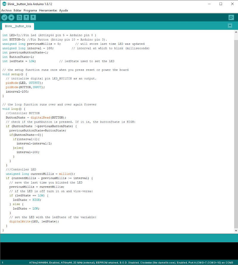
With this code and the modification that I have made on it, what I want (and I hope) to happen is that while the button is pressed, the LED will be on and when the button is not pressed, the LED will stay off.
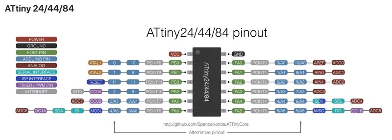
In this code where I use the button and the LED., To know what pins to use in programming, I have based on the pinout scheme of the Datasheet of the ATtiny44 microcontroller, which is the one that has my Hello board. This is the scheme:
This is the code created from the blink:
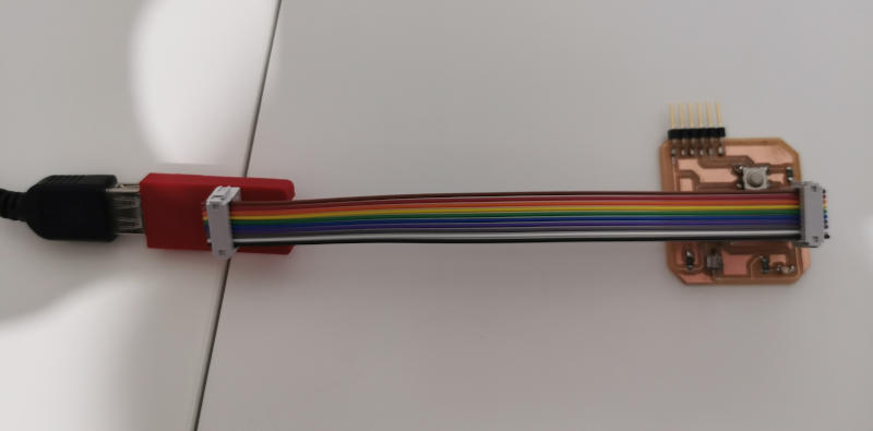
To test if my board works, and the programming, I first make all the necessary connections:
Now I test this programming on my own Hello board.
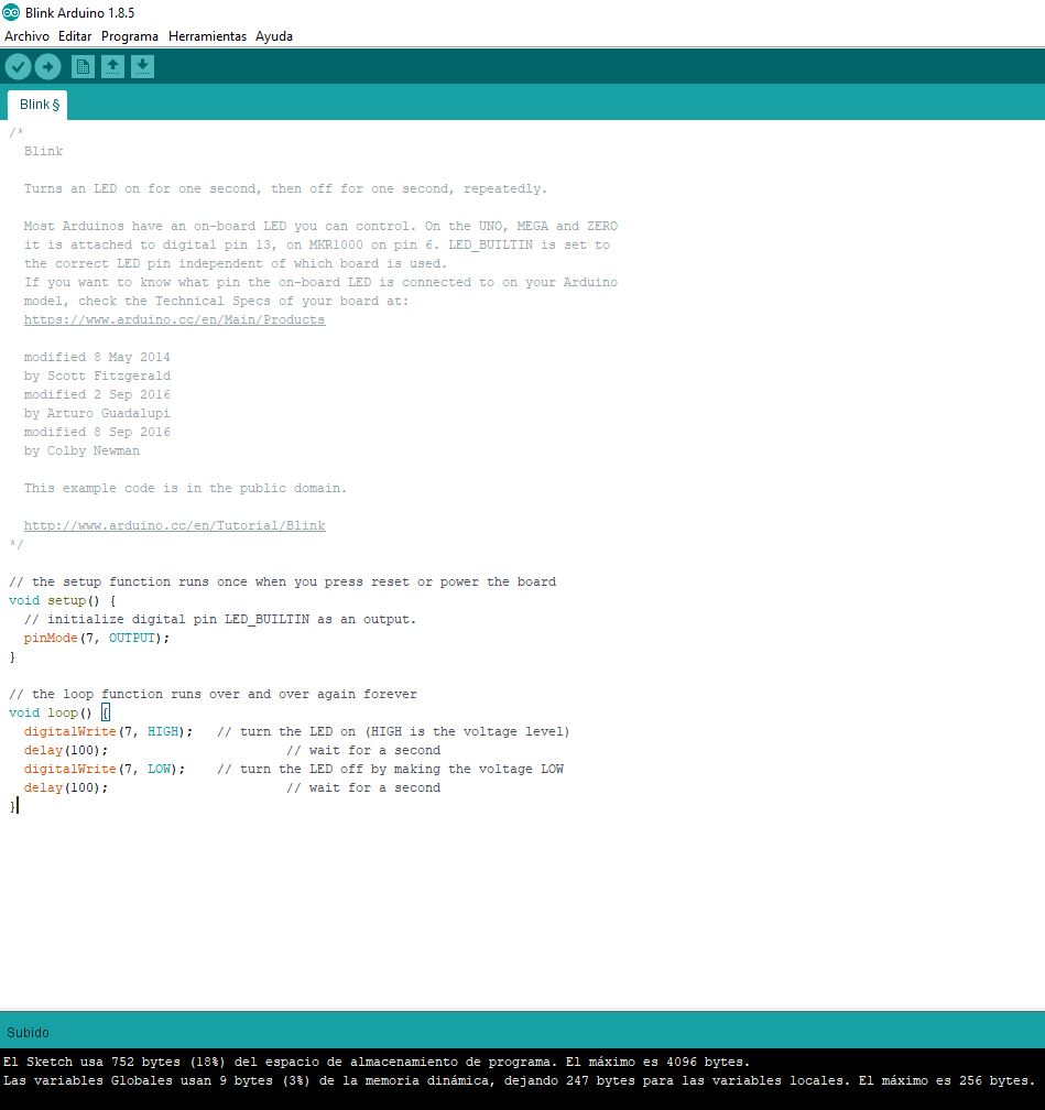
First I test the initial code that I used to check that my programmer worked in the assignment of week 5 and that also helped me to see that my Hello Board created in the assignment of week 7 also worked correctly.
Once I have verified that my first code works, I will test the code modified by me from that blink.
The little finger that made the push button test is that of my little daughter Candela. She is my talisman and surely with her help, everything will work better. :)
And it works well !!!
- Programm file Arduino_program
9.B.3. Pogramming in several environments
To do this section of this assignment I am going to try to program in a C environment using Git Bash.
To do this, I access the Fabacademy Tutorial that can be found at the following link and this is what appears:
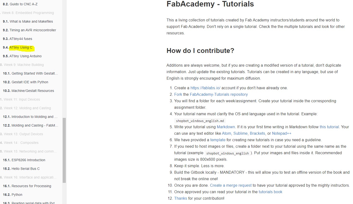
Within all the available tutorials, I look for the one that explains how to program a Microprocessor type ATtiny using the C programming language.
This is the link that allows me to access that information:
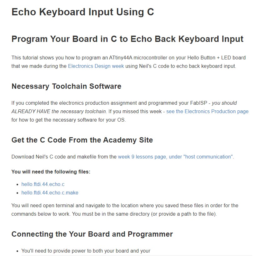
I follow this entire tutorial and program according to the steps specified in it.
I download these C code files listed in the tutorial link, from Neil’s “echo” code:
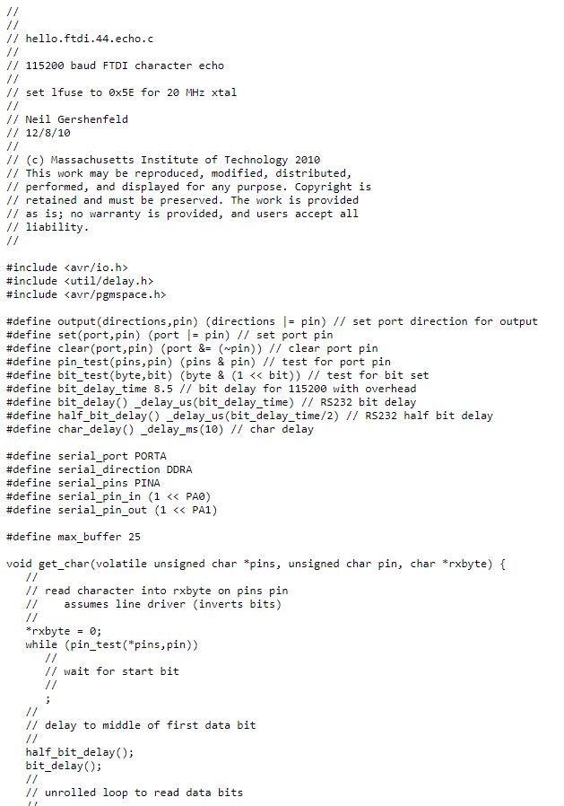
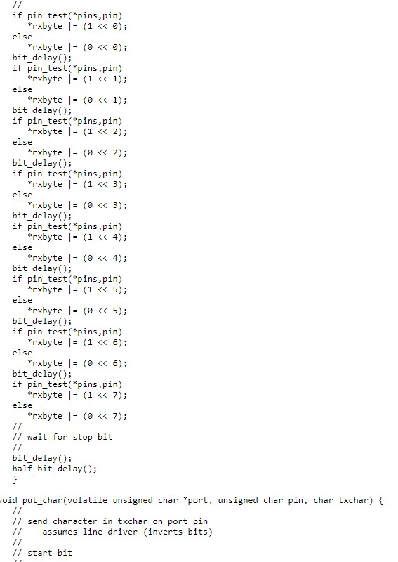
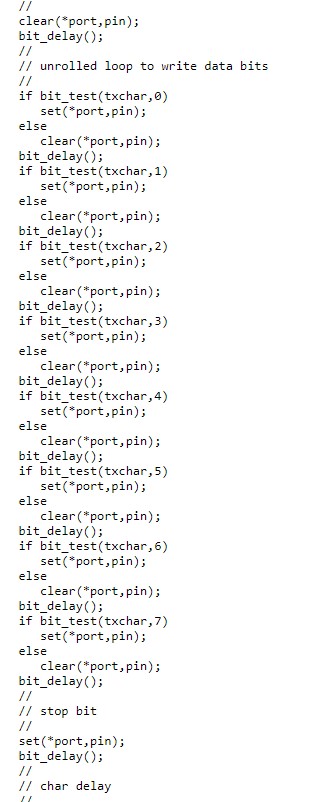
The first file “hello.ftdi.44.echo.c” has this content:
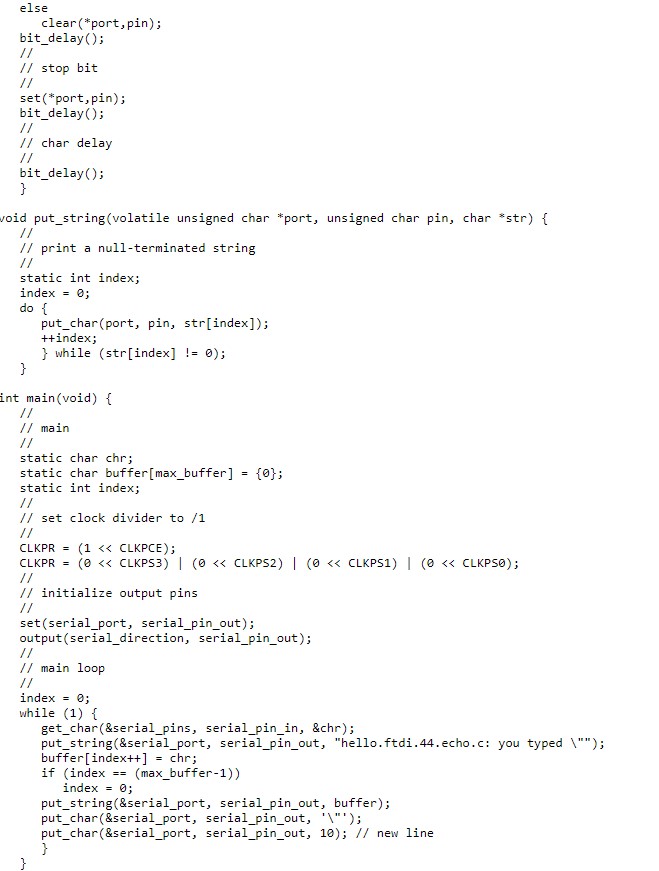
The second file “hello.ftdi.44.echo.c.make” has this content:
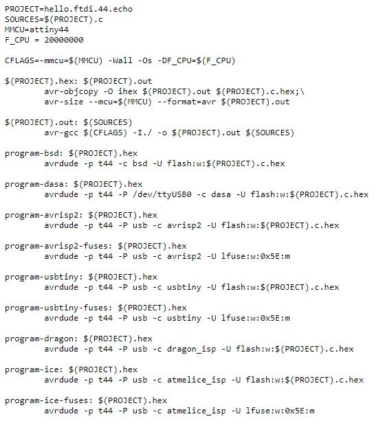
Note : To save the two codes as valid files, in a previously created folder, you must click the right button on each one of them when they have been opened. When saving them I leave them with a .c extension and a .make extension (I remove .txt from both).*
From here I am going to use the Git Bash console to be able to finish this process and execute the programming.
I open git bash and go to the directory where I have saved the downloaded C files.
In my case this folder has as a route: C:\FABACADEMY\w9\ProgramacionesC
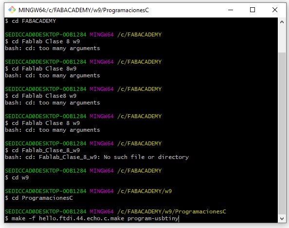
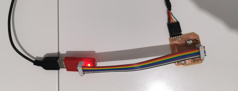
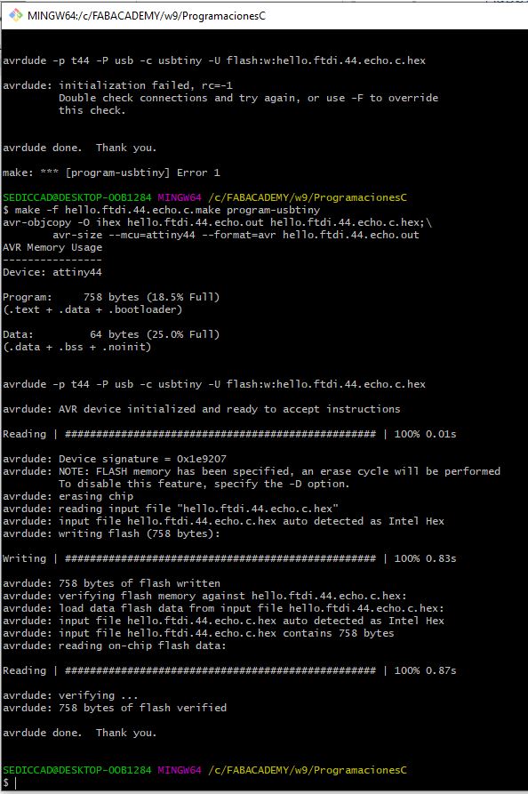
I forgot to connect the programmer to the Hello Board first and it gave me an error so I connected and tried again:
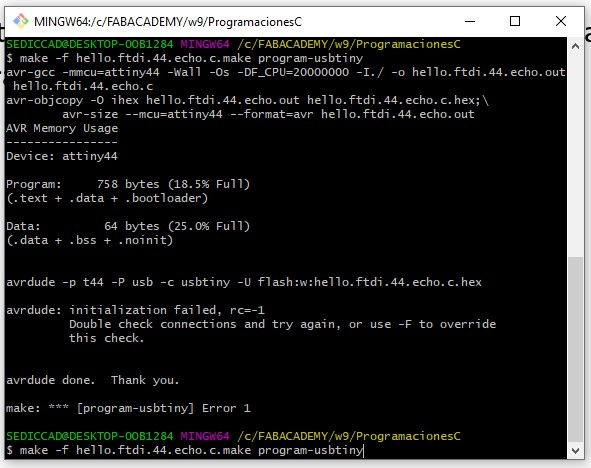
Now, in this attempt, the “echo” code has been loaded in my hello board.
I check that the programming that I have loaded works, for this I open the Arduino IDE program.
This is the sequence of steps that I have taken to do the programming check:
-
I connect the Hello Board with the FTDI cable to the computer.
-
I open the Arduino IDE to use its serial console.
-
From the Arduino IDE, in Tools, I check that the comb 4 port is selected, which is the Hello board in my case.
-
I open the serial console (magnifying glass icon).
-
I confirm that I have selected the 115200 baud option, because in Neil’s code that I have loaded onto the board, that speed is configured and for communication between the console and the Hello board to be possible they have to be at the same speed.
In order to see the result I have recorded a video with the steps I have taken:
The video shows that if I write a character (a letter), press send, my Hello board answers me with that same character.
WOW!!!!!!!! How good 😊