7. Computer-controlled maching
This week assigment
group assignment:
- test runout, alignment, speeds, feeds, and toolpaths for your machine
Group project page
individual assignment:
- make (design+mill+assemble) something big

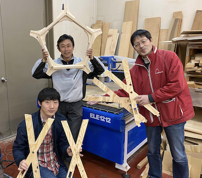
This time took a class at FabLab Nagano.
The lab is located in the National Shinshu University Faculty of Education.
Representative Muramatsu is a graduate of fab academy 2017.
Thank you very much Mr. Muramatsu.
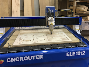
The CNC machine used this time is ELE1212.
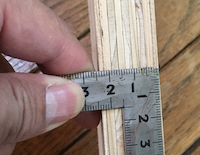
The processed material is 24mm plywood.
It is a bit thick, but I thought it could be used as a window frame for the final project.
Sketch UP → dxf
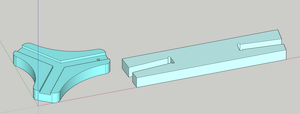
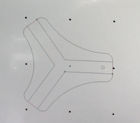
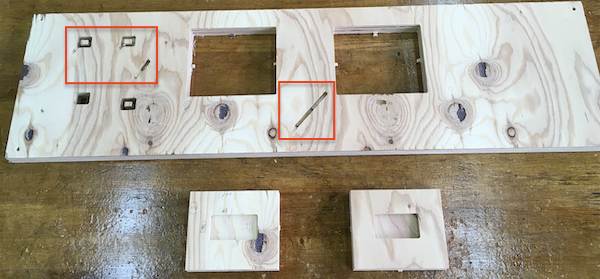
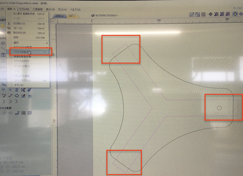
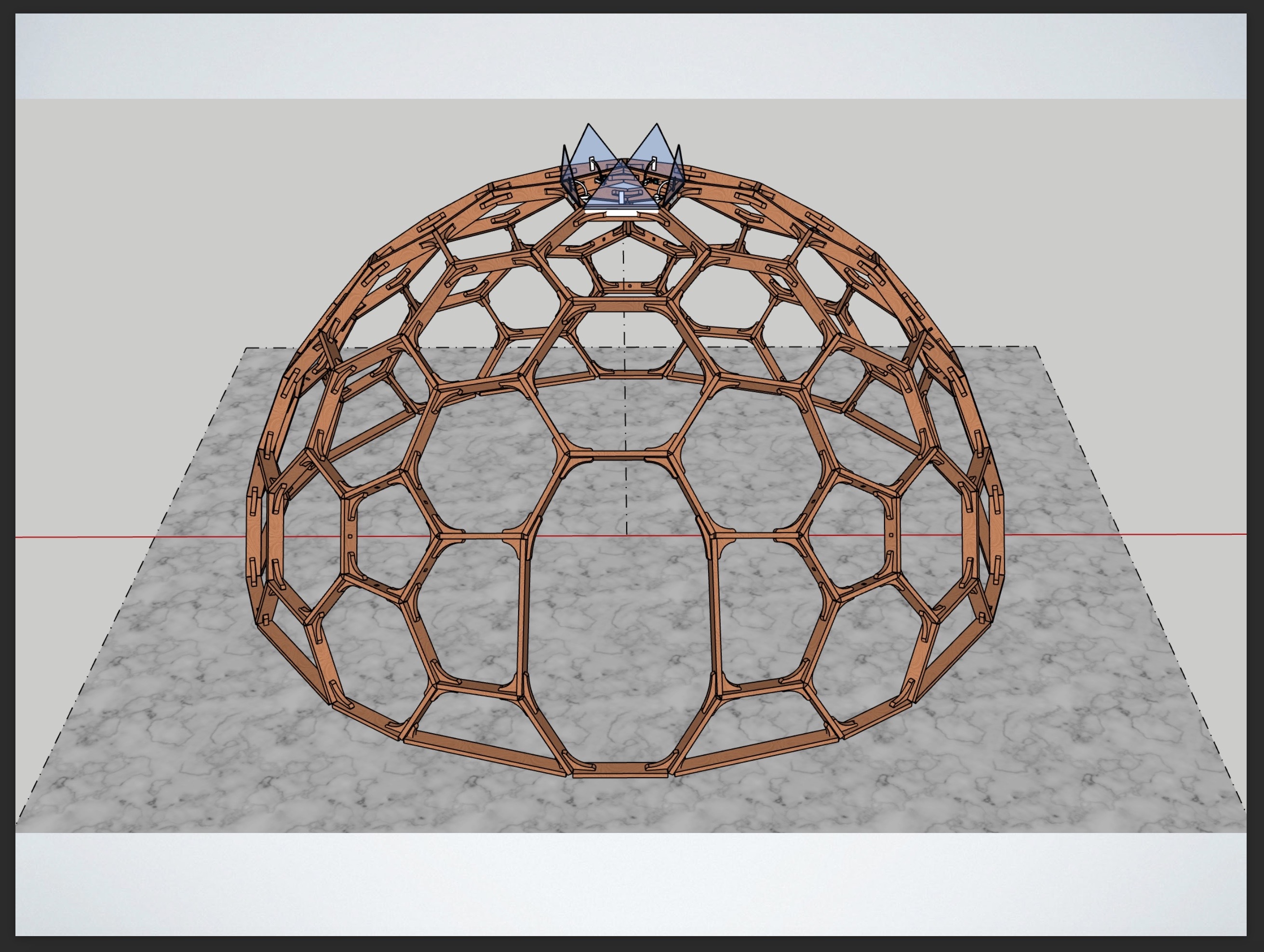
The goal this time is to make a pentagonal part (red frame part) at the top of the dome.
This will later become the sash of the Lotus window of the final project.
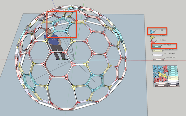
The parts are the following two types, each of which is 5 pieces.
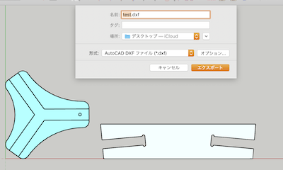
file_data: test.skp
dxf data: test.dxf
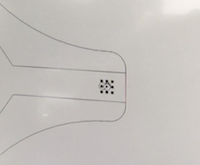
It is important to explain the difference in design between machining by CNC machine and machining by hand.
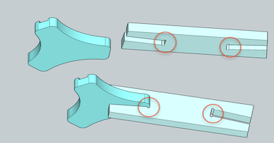
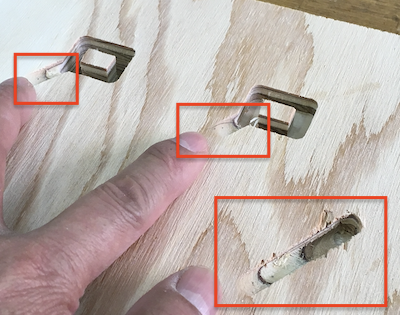
There is a semi-circular cutout in the red circle, which should be machined perpendicularly if it was originally machined by hand, but the CNC bit (blade) is cylindrical, so it cannot be cut out at 90 degrees.
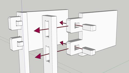
Therefore, it is necessary to make more cuts like this. This is called “dog bone”.

By applying this to a Japanese wooden frame (name:nukisasi_hozo), it looks like this It will be like.
Back to the story.
.skp data was exported to a DXF file so that it can be read by FabLab Nagano software (Cut2D).
Camera → Standard view → Plane
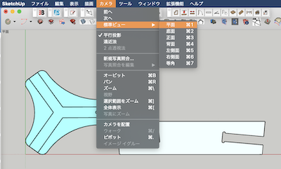
File → Export → 2D graphics
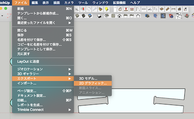
Format → dxf
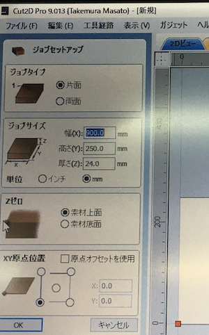
Cut2d
- Create New
- Set job size
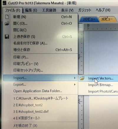
- import file
- Create contour toolpath
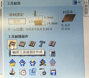
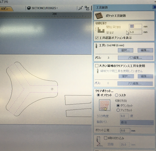
- Pocket tool path creation
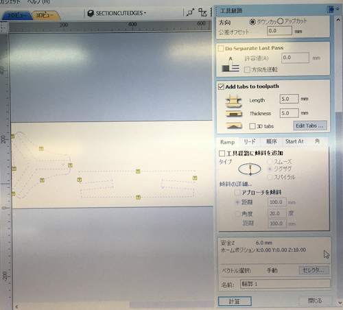
- Attach Tabs. Set to 5mm x 5mm.
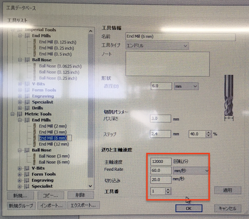
- Set cutting parameters and mill rotation and feedrate
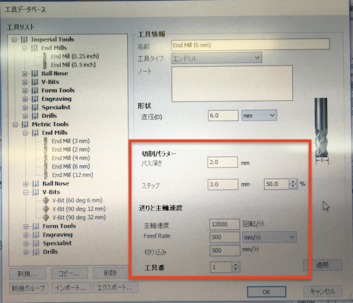
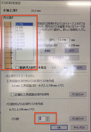
- Set pass
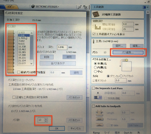
| Speed(RPM) | Feed Rate(mm/minute) | pass | Material(Thickness) |
|---|---|---|---|
| 12000 | 500 | 13 | Plywood 24 mm |
- Select a line according to the processing depth and type, and combine the vectors into a closed figure
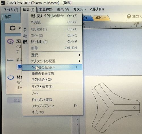
But here’s the problem.
For some reason, the vectors could not be combined.
Dr. Muramatsu’s advice was to create a 2D drawing with combined vectors using “corelDRAW”.
corelDRAW
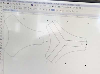
It’s easy and important to notice, but for the first time I’ve noticed that we need to group each cut type and that it needs to be a closed vector.
Select a shape → right click → group objects (Ctrl + C)
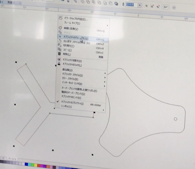
Select a shape → right click → convert to curve (Ctrl + Q)
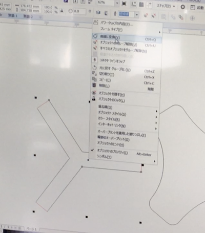
Now I have a closed curve grouping.
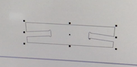
Group each
Three groups were put together.
FLE1212 Cut test
First, how to fix the material.
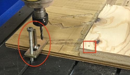
I forgot to take a picture, so it’s not a very good one, but the red circle on the left held the CNC machine and the veneer below in place.
The material to be machined was screwed together at the red circle on the right.
Next, I adjusted the machining origin.
I don’t have a picture of this too, so I draw it as a diagram.
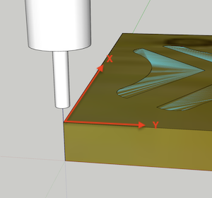
I moved the X and Y axes to where I wanted to start machining, then clicked on the zeroX and zeroY keys in mach3 (red frame) to set them.
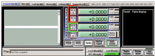
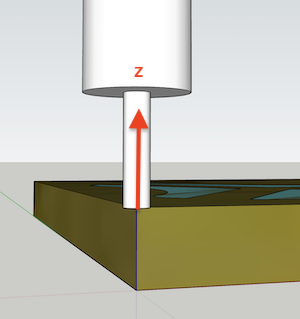
Next, I clicked on zeroZ (green box) when the Z axis (height) was in contact with the material to be machined.
With this setting, we made a test cut with a simple square once before the actual production.
First of all, it turned out that the feed speed was too slow.
Another problem is that the mill goes down on the way from the origin to the cutting point, causing the plate to be cut.
Even more mysteriously, this phenomenon happened or did not happen.
The mill was finally damaged after repeated emergency stops.
On the first day this could not be resolved and the work did not proceed.
Vcarve Pro
Mr. Muramatsu installed Vcarve pro because the yesterday problem could be due to software.
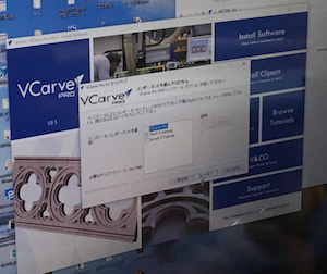
The interface and operation were almost the same as Cut2 pro.
It was easy to combine vectors, which was difficult with Cut2D.
| Speed(RPM) | Feed Rate(mm/minute) | pass | Material(Thickness) |
|---|---|---|---|
| 12000 | 3600 | 9 | Plywood 24 mm |
Mach3
G code (text style) created by Vcarve Pro was read by Mach3 and processing started.
Processing has started normally this time.
When I started processing with this setting, the speed seemed too fast. I heard that I could adjust the speed and rotation during machining with Mach3, so I tried it.
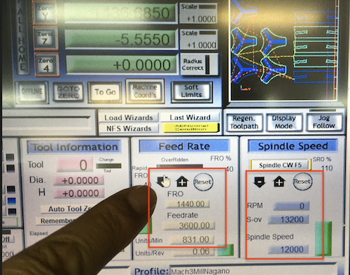
I changed the numerical values in the middle of processing and saw the situation.
If the number of revolutions is too high (more than 13600) the chips will burn light brown.
If you increase the moving speed too much, there will be a lot of wood fluff.
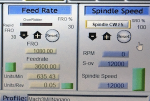
As a result, this figure seemed to be good.
| Speed(RPM) | Feed Rate(mm/minute) | pass | Material(Thickness) |
|---|---|---|---|
| 12000 | 1080 | 9 | Plywood 24 mm |
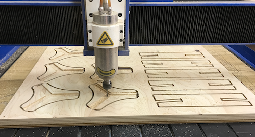
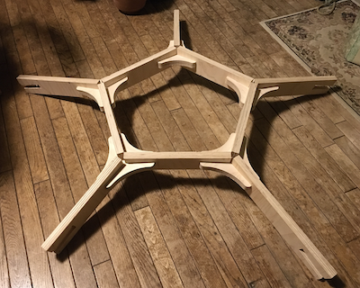
I was worried if I could make a pentagon without cutting, but I could do it well.
This pentagonal window frame will be used in the final project.
Last but not least, the CNC failure seems to be due to poor cable contact.
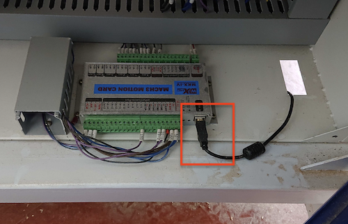
It seems that there was a cable on the floor where people walked, and that the connection was strained when the feet touched.
As a countermeasure, re-wiring along the wall will solve the problem.
We are grateful to Dr. Muramatsu for taking the precious time and helping us while he was busy.
Thank you very much.
Data download
sketch up data: test.skp
dxf data: test.dxf
vcarve data:vcarve-01.crv
[Appendix] A dome frame drawing with a diameter of 4 m that can be processed by a CNC machine, which is currently under development.
FabDome deta: FabDome2.skp