16.Wildcard week
This week assigment
Design and produce something with a digital fabrication process (incorporating computer-aided design and manufacturing) not covered in another assignment, documenting the requirements that your assignment meets, and including everything necessary to reproduce it. Possibilities include (but are not limited to):
Issue of the Week.
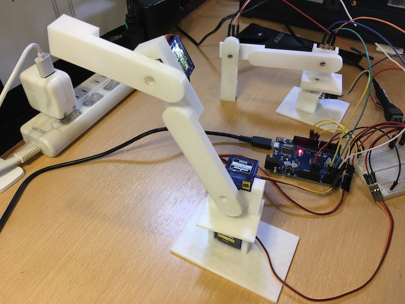
Choice for this week’s challenge: I decided to build a mini robotic arm.
What I want to try.
There are two things I want to try this time.
-
it works exactly as I traced it with my mouse. (Preferably with a brush.)
-
control the main body with another arm made of variable resistance.
In the future, I would like to build a machine that uses a robotic arm to plant trees, grow trees, and process wood.
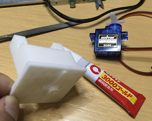
Materials
Three types of servos
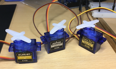
- SG90 → datesheet
- KY66 → I couldn’t find the data sheet so I considered it equivalent to SG90.
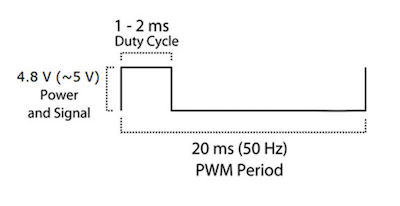
The servo motor is controlled by sending PWM signals to the orange signal line.
In the case of the servo motor (SG-90), the PWM cycle is 20ms.
The angle of the motor can be controlled by the high period of the PWM signal of 20ms per cycle.
The following specifications are taken from the SG-90 datasheet.
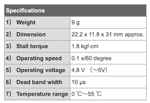
(4) indicates the speed of the axis, i.e., it takes 0.1 seconds to rotate 60 degrees.
(6) controls the servo motor with a pulse width of 1 to 2 milliseconds, and This is an angle of 180 degrees x (1 millisecond/10 microseconds). Expressed in terms of angle, it is 180 degrees x (1 millisecond/10 microseconds), which means that it can be controlled in units of 1.8 degrees. The lower the value, the higher the resolution, but it is easier to respond to small changes in the signal due to noise and other factors. The lower the value, the higher the resolution, the more sensitive it is to small changes in the signal due to noise and so on. There are some servo motors that can adjust this value. Although there is a servo motor that allows you to adjust this value, this value is fixed at 10μs in the case of SG-90. measure
Translated with www.DeepL.com/Translator (free version)
variable resistor
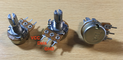
- B10K
Drawing
I used SketchUp to create it.
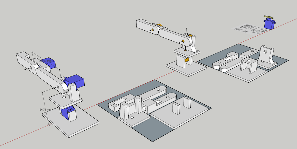
Drawing data → robotarm.skp
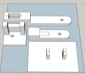
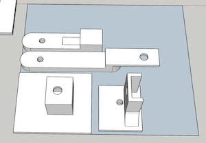
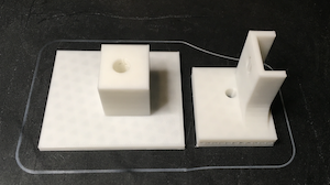
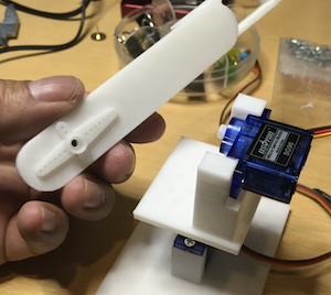
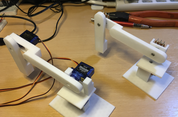
There are two types of arms.
The one on the left is for the servo motor and the one on the right is for the potentiometer.
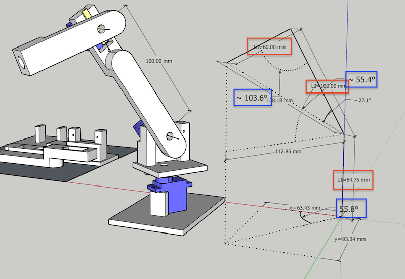
What I learned a lot from the actual drawing was that it was possible to reproduce all kinds of movements with the robot arm by finding the lengths of the L1, L2 and L3 arms and their respective opening angles and programming them.
Although we were not able to execute it this time, we would definitely like to try it in the future.
Translated with www.DeepL.com/Translator (free version)
I had made a hole in the tip of the arm to insert a pen at the time of drawing, but later I found out that the servo (SG90) could not bear the weight of the pen, so I gave up trying to write letters.
Perhaps if I made the frame more lightweight and cut the pen shorter, I might be able to do it.
3D printing
- Servo motor arm
stl data → arm_servo.stl
- Potentionmeter arm
stl data → arm_poten.stl
I used the free Ultimaker Cura software to create the G-code.
- Layer height is 0.2 mm.
- Support is 75° (for all)
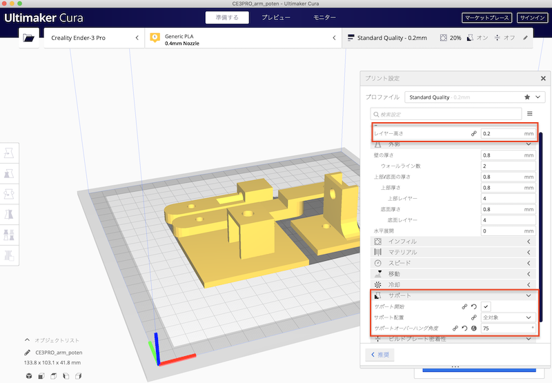
Ultimaker is an excellent free software that is easy to use and easy to check simulations with.
This is the first time I encountered a problem with my printer(ender), which I bought last month and has been working well until now.
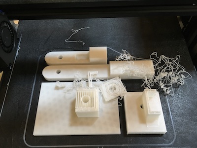
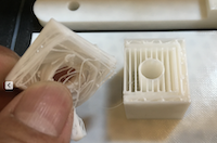
I could see that the destruction had started at the back of the pedestal digging in, so I made a simple correction to the drawing.
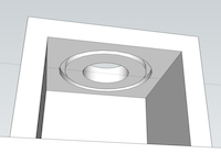
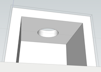
I printed it again and it worked fine.
Assembly (servo side)
Arm.
Set the base of the foundation part
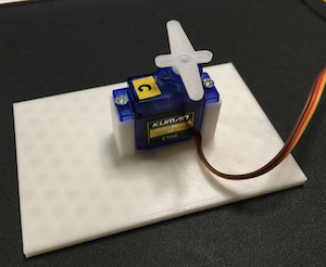
I glued the gauge of the servo to the bottom of the second base.
I also glued the gauge to the arm of the second stage.
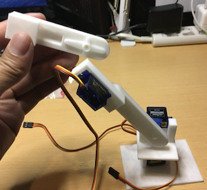
Install the third servo on the second arm.
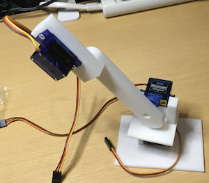
Install the 3rd stage arm.
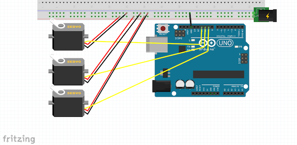
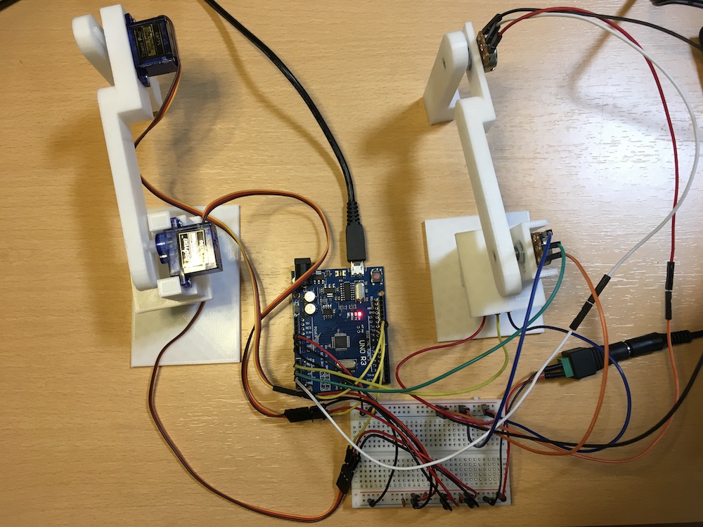
Wiring.
This is the first time to draw the picture of wiring using fritzing. I don’t know how to use fritzing yet, so I uploaded this picture.
Programming
The Arduino IDE was used to test the programming behavior as follows
// Control each of the three servos.
#include <Servo.h>

Servo myservo1, myservo2, myservo3;

int pos = 0;

void setup() {
  Serial.begin(115200);
  myservo1.attach(9, 550, 2600);  //KY66
  myservo2.attach(10, 630, 2400); //SG90
  myservo3.attach(11, 630, 2400); //SG90
}

void loop() {
  for (pos = 0; pos <= 180; pos += 1) {  // 0〜180One at a time + 1 to (upright)
    // in steps of 1 degree
    myservo3.write(180-pos/2-34);  // Change the direction of rotation
    myservo2.write(180-pos/2-4);  // and adjust the position
    myservo1.write(pos);
    delay(25);
  }
  for (pos = 180; pos >= 0; pos -= 1) {
    myservo3.write(180-pos/2-34); // Set upright from the start
    myservo2.write(180-pos/2-4);
    myservo1.write(pos);
    delay(25);
  }
}
PWM Control.
Servo has a lot of noise at the time of operation, so I am often troubled by it. A lot of know-how on the web is just a matter of moving it around and that’s it, so this is a good place to start. The goal is to understand the behavior of the servo, and to get into the mind of the servo.
There are three terminals coming out of the servo motor. The red one connects to the positive side of the power supply, and the black or brown one connects to ground (negative side of the power supply). Orange or yellow is connected to the control signal. The power supply voltage and control signals are supplied at 4.8V.
Translated with www.DeepL.com/Translator (free version)

The graph below shows the timing chart for the control signal. The horizontal axis shows the time. The unit is in milliseconds. The vertical axis shows the voltage. The flat area at the bottom is 0V. The peak of the pulse is 4.8V.
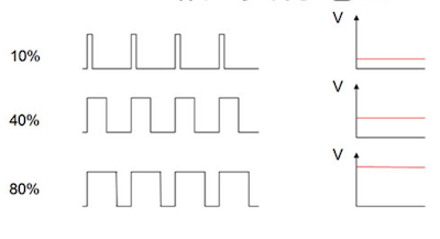
What is PWM? PWM stands for “Pulse Width Modulation”, and in Japanese it means “Pulse Width Modulation This is a method of controlling electric power by repeating on and off, known as “power on/off”. We have already discussed above that the voltage needs to be raised or lowered to control the output (speed) of the motor. However, the main focus of this paper is to control high and low voltage by PWM.
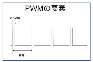
Sometimes we use the expression frequency, in which case the number of times this cycle repeats in one second is used as the value The unit is the reciprocal of the period. This is the reciprocal of the period, and the unit is Hertz (Hz). The pulse width/period is called the duty ratio and is expressed as a percentage.
In the case of SG-90, it takes 0.3 seconds or 300 milliseconds to move from 0 degrees to 180 degrees. So adjust this value if the movement is awkward.
- I managed to get it to work as I wanted.
Processing_test
This time, we used processing to move the robot arm along with the mouse movement.
The code for the processing side
import processing.serial.*;
Serial myPort; // serial port

float i;
float j;

int x = 0, y = 200, z = 20;

void setup() {
  size(800, 520);
  strokeWeight(10);
  background(200);
  myPort = new Serial(this, Serial.list()[1], 9600);
}

void draw() {
  if (mousePressed == true){
    line(mouseX, mouseY, pmouseX, pmouseY);
    z = 0;
  }else{
    z = 20;
  }

  x = pmouseX/4;
  y = pmouseY/4;


  println(x + ", " + y + ", " + z);
  myPort.write('P');
  myPort.write(x);
  myPort.write(y);
  myPort.write(z);

  //delate
  if ((keyPressed == true) && ((key == 'q'))) {
    background(200);
  }
}
Arduino side code
#include <Servo.h>

Servo myservo1, myservo2, myservo3;

float th1=90.0,th2=90.0,th3=90.0;
float phi,ld,l;

float L1=92,L2=137,L3=158;

int x,y,z;

void setup() {
  Serial.begin(9600);
  myservo1.attach(9, 500, 2420);  //KY66-C
  myservo2.attach(10, 820, 2140); //SG90-B
  myservo3.attach(11, 820, 2140); //SG90-A
  set_servo();
  ik(0, 170, 230);  //初期姿勢
}

void loop() {
  if (Serial.available() >= 4) {
    if ( Serial.read() == 'P' ) {
      x = Serial.read()-50;
      y = 240 - Serial.read();
      z = Serial.read();
      ik(x, y, z);
    }
  }
}

void ik(float x,float y,float z){
  th1=atan2(y,x);
  l=sqrt(x*x + y*y);
  ld=sqrt(l*l + (z-L1)*(z-L1));
  phi=atan2((z-L1),l);
  th2=phi + acos((ld*ld+L2*L2-L3*L3)/(2.0*ld*L2));
  th3=asin((ld*ld-L2*L2-L3*L3)/(2.0*L2*L3)) + M_PI /2.0;
  th1=th1*180.0/M_PI ;
  th2=th2*180.0/M_PI ;
  th3=th3*180.0/M_PI ;
  set_servo();
}

void set_servo(){
    myservo1.write(th1);
    myservo2.write(th2);
    myservo3.write(th3);
}
The page I was referring to https://homemadegarbage.com/arm03
It’s a little awkward, but I thought it was cute.
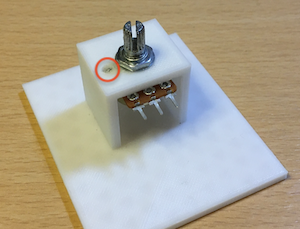
Assembly (potentiometer side)
Set the foundation part (I drilled a 2 mm hole in the red circle)
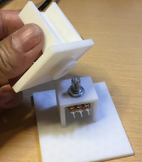
Set the second stage foundation.
If it was hard to get the knob in, I heated it up and inserted it in and it fit.
Set the potentiometer on the second stage.
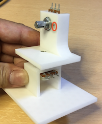
Set the arm.

2 sets completed.
operational test
Arduino IDE
#include <Servo.h>

Servo myservo1, myservo2, myservo3;

float th1=90.0,th2=90.0,th3=90.0;
float val1, val2, val3;

void setup() {
  Serial.begin(9600);
  myservo1.attach(9, 550, 2600);  //KY66
  myservo2.attach(10, 630, 2400); //SG90
  myservo3.attach(11, 630, 2400); //SG90
  set_servo();
}

void loop() {
  val1 = analogRead(A1);
  val2 = analogRead(A2);
  val3 = analogRead(A3);

  th1 = map(val1, 0, 550, 0.0, 180.0); // myservo3
//  if(th1 >= 180.0){
//    th1 = 180.0;
//  }else if(th1 <= 0.0){
//    th1 = 0.0;
//  }

  th2 = map(val2, 0, 550, 0.0, 180.0); // myservo2
//  if(th2 >= 180.0){
//    th2 = 180.0;
//  }else if(th2 <= 0.0){
//    th2 = 0.0;
//  }
//
  th3 = map(val3, 0, 550, 0.0, 180.0); // myservo1
//  if(th3 >= 180.0){
//    th3 = 180.0;
//  }else if(th3 <= 45.0){
//    th3 = 45.0;
//  }

  set_servo();
}

void set_servo(){
    myservo1.write(th1);
    myservo2.write(th2);
    myservo3.write(th3);

}
It’s a little awkward, but for the most part it’s the same movement.
Next, I tested the potentiometer arm remembering the movement of the potentiometer arm and operating on its own.
Arduino IDE
#include <Servo.h>

Servo myservo1, myservo2, myservo3;

float th1=90.0,th2=90.0,th3=90.0;
float val1, val2, val3;

boolean rec = false;
boolean play = false;
int playCnt = 0;
int xyz[250][3] = {};
int delayTime = 50;


void setup() {
  Serial.begin(9600);
  pinMode(13, OUTPUT);

  myservo1.attach(9, 550, 2600);  //MG995
  myservo2.attach(10, 630, 2400); //DS3115
  myservo3.attach(11, 630, 2400); //DS3115
  set_servo(th1, th2, th3);
}

void loop() {
  val1 = analogRead(A1);
  val2 = analogRead(A2);
  val3 = analogRead(A3);

  th1 = map(val1, 0, 550, 0.0, 180.0); // myservo3
//  if(th1 >= 180.0){
//    th1 = 180.0;
//  }else if(th1 <= 0.0){
//    th1 = 0.0;
//  }

  th2 = map(val2, 0, 550, 0.0, 180.0); // myservo2
//  if(th2 >= 180.0){
//    th2 = 180.0;
//  }else if(th2 <= 0.0){
//    th2 = 0.0;
//  }
//
  th3 = map(val3, 0, 550, 0.0, 180.0); // myservo1
//  if(th3 >= 180.0){
//    th3 = 180.0;
//  }else if(th3 <= 45.0){
//    th3 = 45.0;
//  }

  //Reading Serial Monitor Input
  char c;
  if ( Serial.available() > 0 ) {
    c = Serial.read();
    if(c=='p'){
      play = true;
    }else if(c=='r'){
      rec = !rec;
    }
  }

  if(rec){  //audit trail
    digitalWrite(13, HIGH); //Red LED lighting
    xyz[playCnt][0] = (int)th1;
    xyz[playCnt][1] = (int)th2;
    xyz[playCnt][2] = (int)th3;
    set_servo(th1, th2, th3);
    playCnt++;
    Serial.println(playCnt);
    delay(delayTime);
  }else if(play){  //Operation Playback
    for(int i = 0; i < playCnt; i++){
      set_servo(xyz[i][0], xyz[i][1], xyz[i][2]);
      Serial.println(i);
      delay(delayTime);
    }
    play = false;
    playCnt = 0;
  }else {//normal time
    digitalWrite(13, LOW);
    set_servo(th1, th2, th3);
  }
}

void set_servo(float th1, float th2, float th3){
    myservo1.write(th1);
    myservo2.write(th2);
    myservo3.write(th3);
}
The Arduino IDE’s serial monitor starts recording the operation with the r input and stops recording again with the r input.
When recording, the connected red LED (No13pin) is turned on.
The recorded (memorized) action is played back by the p input.