6. Electronics design
This week assigment
group assignment:
- group project:
use the test equipment in your lab to observe the operation
of a microcontroller circuit board
Group project page
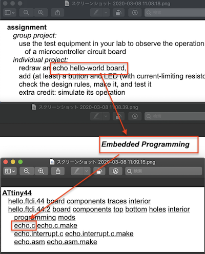
individual project:
- redraw an echo hello-world board,
add (at least) a button and LED (with current-limiting resistor)
check the design rules, make it, and test it
- extra credit: simulate its operation
echo hello-world board
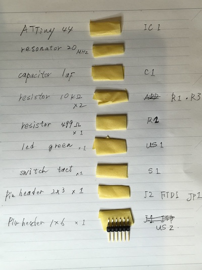
component
| Parts | Description | Quantity | Eagle.NO |
|---|---|---|---|
| microcontroller | ATTiny 44 | 1 | IC01 |
| resonator | 20MHz322 | 1 | XTRAL |
| capacitor | 1uF | 1 | C1 |
| resistor | 10KΩ | 2 | R1.R2 |
| resistor | 499Ω | 1 | R2 |
| LED | green | 1 | US1 |
| tactile switch | 1 | S1 | |
| Pin header | 2x3 | 1 | JP1 |
| Pin header | 1x6 | 1 |
Drawing
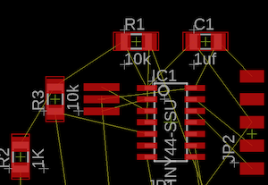
Circuit diagram
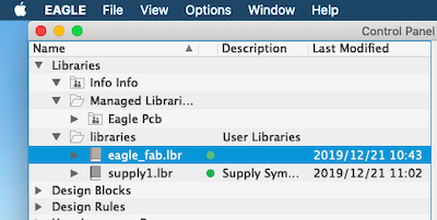
Fab.ibr has already been downloaded.
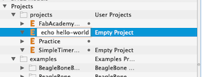
Creating a new project
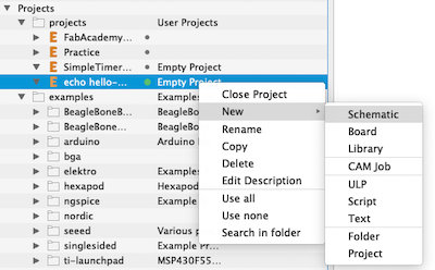
Creating a new schematic
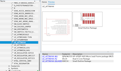
ATtiny45
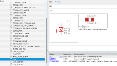
LED
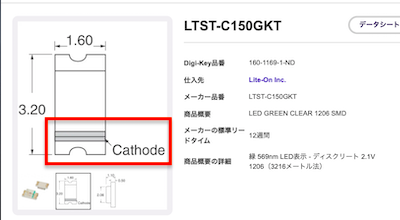
For the LED, the direction of the cathode (-) was checked in the data sheet.
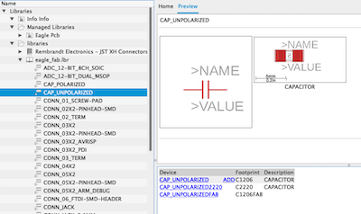
capacitor
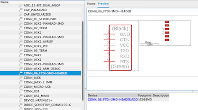
PIN header 1x6
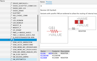
resistor
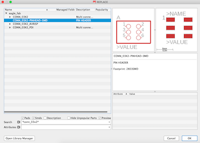
PIN heder 2x3
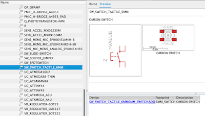
switch
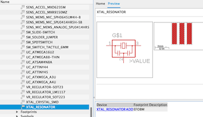
resonator
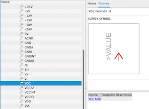
VCC
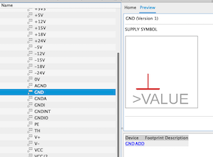
GND
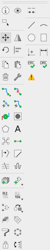
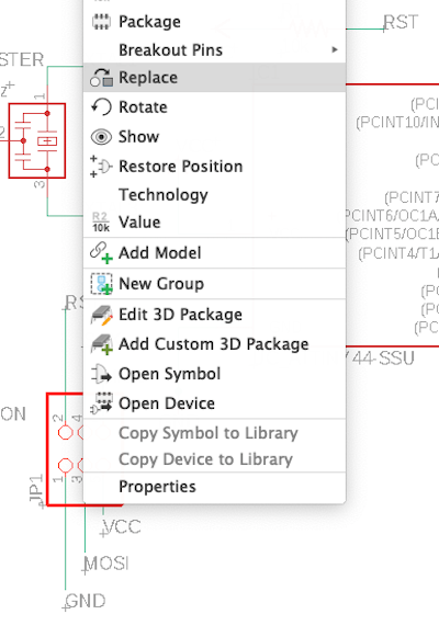
move = moves parts
rotate = rotates parts
copy
delete
net = connect components
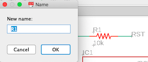
name = names parts and lines.
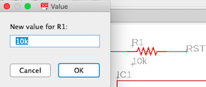
value = adds a value to parts such as “10KΩ” for register
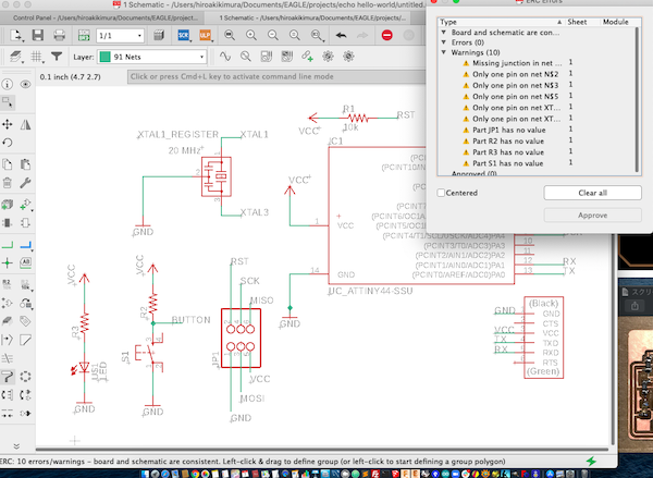
ERC = If there are no errors in the wiring, nothing will be displayed when you click.
This time there were some cautions, but I thought it was fine and proceeded to the next. (But this became a problem later …)
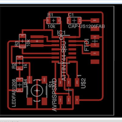
Creating a pattern diagram
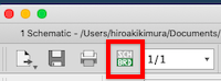
Next, create a board (click BRD)
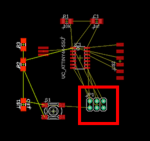
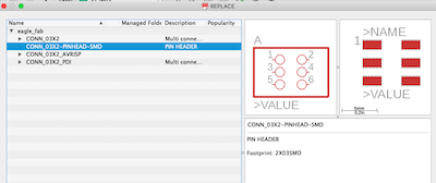
It was placed in most positions, but changed because 2x3 PIN3 was a perforated type.
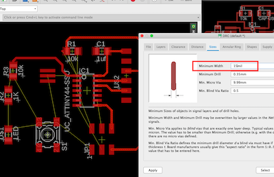
Set the environment related to pattern restrictions and rules according to the board production environment.
This time, we use mods with SRM-20 and set up rules that assume cutting.
DRC (pattern check) is determined based on this setting.
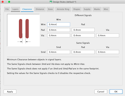
Set as above from edit> design rule> clearance.
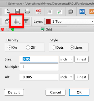
Grid settings
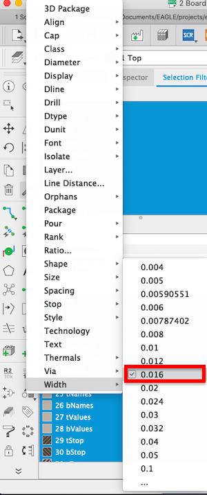
Line width setting
 week
week
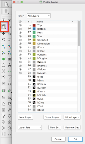
Layer settings
If set the minimum line width, it seems that diagonal lines will be inserted in the wiring when it becomes less than that width.
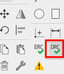
DRC rror checking
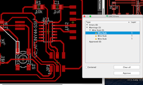
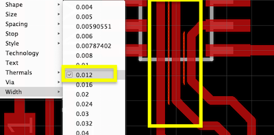
The line width of the part where the space is less than 0.4 mm has been reduced.
The layer was changed to “48 documents” to design the board outline.
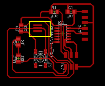
Next, I used the polygon tool to draw a rectangular shape.
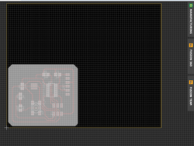
The white rectangle shows the outline of the board.
Adjusted the yellow rectangular area to match the white shape.
Design data.
Board Design: hello_echo.brd
Schematich Design: hello_echo.sch
Export image
Export PNG image from EAGLE
Unnecessary display is canceled from setting from option> set…
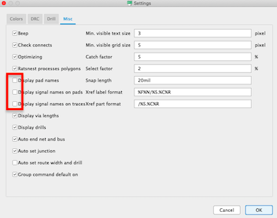
Specify the display layer as Top1, select “File> Export> Image”, and export the image in png format.
Next, I changed the resolution to 800dpi and set it to monochrome.
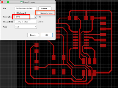
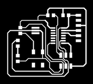
I was able to export it as a png file.
I also exported the outer frame.
Mods
I loaded the png file. After checking dpi, it was 800, but it was output as it was.
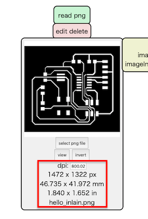
I confirmed the path.
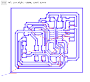
Milling
I used Roland SRM-20 using the 5th week.
Set 1/64 bit and carved internal route.
Then I changed the bit to 1/32 and started cutting the contour.
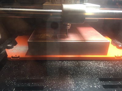
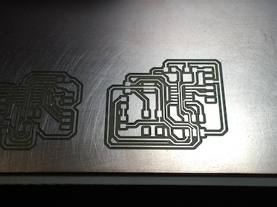
I did well.
Soldering
I didn’t take any pictures because I was too concentrated, but I passed the continuity test.
program
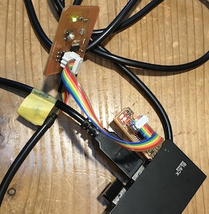
The echo hello board was programmed using the FabISP board created in the fifth week.
-
Connect Mac USB port to 6pin header using FTDI / USB serial converter cable
-
Connect Mac USB port to 6pin isp header using USB cable
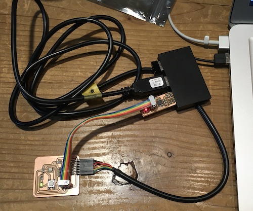
It is necessary to check the position of the pin header
By enlarging the board diagram, the names of the wiring appear.
Click echo.c
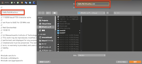
Save the opened hello.ftdi.44.echo.c file to the desktop.
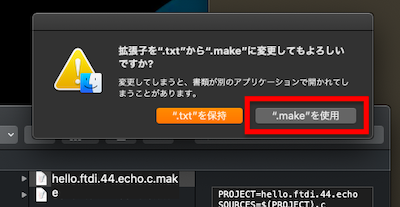
Change the extension to .make and save.
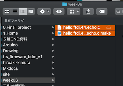
I also created a .c file and saved it in the week06 folder.
Following the instructions, I program the sample C code into the board.
⭐️The steps are as follows
$ make -f hello.ftdi.44.echo.c.make
$ sudo make -f hello.ftdi.44.echo.c.make program-usbtiny-fuses
$ sudo make -f hello.ftdi.44.echo.c.make program-usbtiny
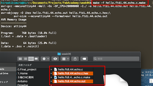
1.First, I created a folder called week6.
There, I wrote a command to create hello.ftdi.44.echo.c.
This should have created the files ‘hello.ftdi.44.echo.c.hex’ and ‘hello.dtdi.44.echo.c.out’.
2.Then enter the following command.
$ make -f hello.ftdi.44.echo.c.make program-usbtiny-fuses
avr-objcopy -O ihex hello.ftdi.44.echo.out hello.ftdi.44.echo.c.hex;\
    avr-size --mcu=attiny44 --format=avr hello.ftdi.44.echo.out
AVR Memory Usage
----------------
Device: attiny44

Program:     760 bytes (18.6% Full)
(.text + .data + .bootloader)

Data:         64 bytes (25.0% Full)
(.data + .bss + .noinit)


avrdude -p t44 -P usb -c usbtiny -U lfuse:w:0x5E:m
avrdude: Error: Could not find USBtiny device (0x1781/0xc9f)

avrdude done.  Thank you.

make: *** [program-usbtiny-fuses] Error 1
Error: Could not find USBtiny device (0x1781/0xc9f)
Since it doesn’t recognize the USBtiny device, check the 6pin connection and try again.
Challenge again
$ make -f hello.ftdi.44.echo.c.make program-usbtiny-fuses
avr-objcopy -O ihex hello.ftdi.44.echo.out hello.ftdi.44.echo.c.hex;\
    avr-size --mcu=attiny44 --format=avr hello.ftdi.44.echo.out
AVR Memory Usage
----------------
Device: attiny44

Program:     760 bytes (18.6% Full)
(.text + .data + .bootloader)

Data:         64 bytes (25.0% Full)
(.data + .bss + .noinit)


avrdude -p t44 -P usb -c usbtiny -U lfuse:w:0x5E:m

avrdude: AVR device initialized and ready to accept instructions

Reading | ################################################## | 100% 0.00s

avrdude: Device signature = 0x1e9207 (probably t44)
avrdude: reading input file "0x5E"
avrdude: writing lfuse (1 bytes):

Writing | ################################################## | 100% 0.01s

avrdude: 1 bytes of lfuse written
avrdude: verifying lfuse memory against 0x5E:
avrdude: load data lfuse data from input file 0x5E:
avrdude: input file 0x5E contains 1 bytes
avrdude: reading on-chip lfuse data:

Reading | ################################################## | 100% 0.00s

avrdude: verifying ...
avrdude: 1 bytes of lfuse verified

avrdude: safemode: Fuses OK (E:FF, H:DF, L:5E)

avrdude done.  Thank you.
3.Enter the third code
$ make -f hello.ftdi.44.echo.c.make program-usbtiny
avr-objcopy -O ihex hello.ftdi.44.echo.out hello.ftdi.44.echo.c.hex;\
    avr-size --mcu=attiny44 --format=avr hello.ftdi.44.echo.out
AVR Memory Usage
----------------
Device: attiny44

Program:     760 bytes (18.6% Full)
(.text + .data + .bootloader)

Data:         64 bytes (25.0% Full)
(.data + .bss + .noinit)


avrdude -p t44 -P usb -c usbtiny -U flash:w:hello.ftdi.44.echo.c.hex

avrdude: initialization failed, rc=-1
         Double check connections and try again, or use -F to override
         this check.


avrdude done.  Thank you.

make: *** [program-usbtiny] Error 1
Failure.....
Debug
The following errors continued.
Double check connections and try again, or use -F to override this check.
Could not find USBtiny device (0x1781/0xc9f)
⭐️What I tried to improve it.
-
Considering the possibility of poor contact, we piled up solder and cut unnecessary parts with an Ultrasonic Cutter. → No.
-
Considering the poor contact of the 6-pin cable, I rebuilt the cable. → No
-
I tested the energization again. → No
-
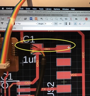
I reviewed the Eagle wiring diagram again.
Then! ! ! I noticed that the wiring of the resonator was different from the others.
mistake
correct
When I searched for the cause of the mistake, I went back to the ERC check for creating the schematic.
When carefully checked, there were “Only one pin on net N $ 2” and four other Warnings.
I ignored it because I thought it was displayed correctly in the schematic.
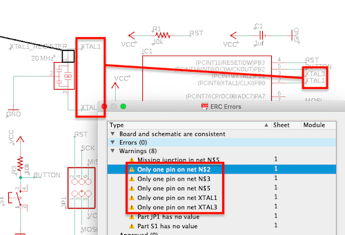
So when I switched to the board, the registers XTAL2,3 were not connected.
The reason for this mistake was that we proceeded without confirming it.
I didn’t believe in autowiring and realized the importance of checking again with my own eyes.
When I modified the schematic and switched to the board, the register wiring was reflected.
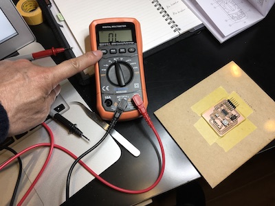
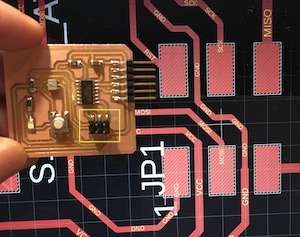
First aid
With the instructor’s advice, I decided to use Polyurethane Enamelled Copper Wire for first aid.
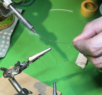
The surface of this copper wire is insulated with polyurethane, but it is said that polyurethane can be peeled only at that part by passing the copper wire into a ball and soldering, and it will be able to conduct electricity.
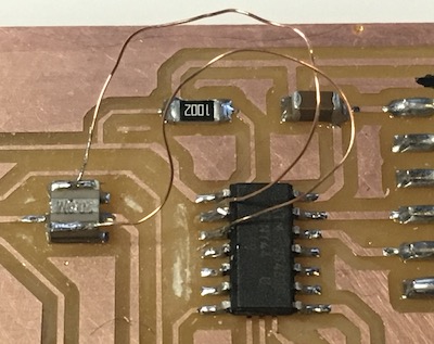
I did first aid in this way.
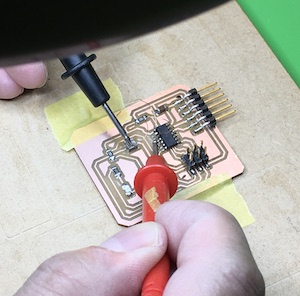
I checked it with a multimeter.
I was able to do it safely.
- 3.Enter the third code again
:$ make -f hello.ftdi.44.echo.c.make program-usbtiny

avr-objcopy -O ihex hello.ftdi.44.echo.out hello.ftdi.44.echo.c.hex;\
    avr-size --mcu=attiny44 --format=avr hello.ftdi.44.echo.out
AVR Memory Usage
----------------
Device: attiny44

Program:     760 bytes (18.6% Full)
(.text + .data + .bootloader)

Data:         64 bytes (25.0% Full)
(.data + .bss + .noinit)


avrdude -p t44 -P usb -c usbtiny -U flash:w:hello.ftdi.44.echo.c.hex

avrdude: AVR device initialized and ready to accept instructions

Reading | ################################################## | 100% 0.00s

avrdude: Device signature = 0x1e9207 (probably t44)
avrdude: NOTE: "flash" memory has been specified, an erase cycle will be performed
         To disable this feature, specify the -D option.
avrdude: erasing chip
avrdude: reading input file "hello.ftdi.44.echo.c.hex"
avrdude: input file hello.ftdi.44.echo.c.hex auto detected as Intel Hex


Writing | ################################################## | 100% 1.17s

avrdude: 760 bytes of flash written
avrdude: verifying flash memory against hello.ftdi.44.echo.c.hex:
avrdude: load data flash data from input file hello.ftdi.44.echo.c.hex:
avrdude: input file hello.ftdi.44.echo.c.hex auto detected as Intel Hex
avrdude: input file hello.ftdi.44.echo.c.hex contains 760 bytes
avrdude: reading on-chip flash data:

Reading | ################################################## | 100% 1.39s

avrdude: verifying ...
avrdude: 760 bytes of flash verified

avrdude: safemode: Fuses OK (E:FF, H:DF, L:5E)

avrdude done.  Thank you.
Succeeded!!!
Thanks to instructor Jun.
Hello world
I tested echoback using the Arduino IDE.
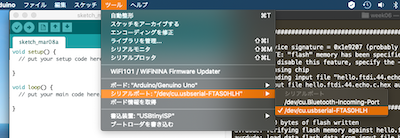
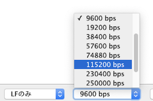
I opened the serial monitor and set the same baud rate 115200bps as the program.
Pressing a key on the keyboard echoed the character back to the serial monitor.
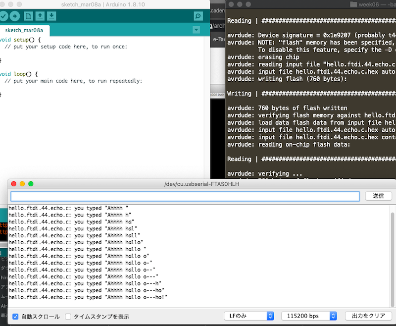
Below is a hero shot😀!
What I learned this week
- Drawing by Eagle
- Writing a program to a microcontroller board with FabTinyISP
Data download
Board Design: hello_echo.brd
Schematich Design: hello_echo.sch