3. Computer controlled cutting
This week assigment
- group assignment:
characterize your lasercutter’s focus, power, speed, rate,kerf, and joint clearance
Group assignment documentation → group page - individual assignment:
cut something on the vinylcutter design, lasercut, and document a parametric construction kit,
Vinyl Cutting
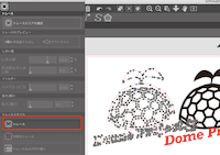
I made a logo for the dome project that I plan to start.
I used SketchBook, a freehand and easy-to-use app on the iPad to create logos.

This time I use Cameo 3.

- Cameo3
I downloaded the control software “silhouette studio” of kameo3, and read the image written in the sketchbook as a .png file.

Set it to the blue line on the left side of the sheet and press the media set button.

Then adjust the size and open the trace panel①
Select trace area ②
Drag around the image to select it ③
It is the place where the part painted in yellow is applied.

Adjust [Threshold] so that the whole image turns yellow.

Click [Trace] to create a cut line around the image.
The raster image has now been changed to a vector.
When you double-click, the coordinate point is also displayed.
Next, make settings before sending.
Select the type of media to be used from the [New cutting condition] pull-down list. → Select sticker, clear
Select [Cut] from the [Action] pull-down list, and specify [Cut] as the cut type. → Select cut
Select the type of cutter blade to be used from the pull-down list of [Tool]. → Select auto blade
Fine-tune the blade length, speed, cutting pressure, etc. according to the thickness of the sticker paper.
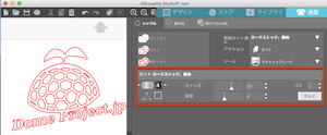
First of all, test with blade length -3, speed -4 and cutting pressure 25

It failed because the base was cut.
Again, test with blade length-3, speed-7mm, cut pressure 14

This time it feels good. Press send to start cutting.
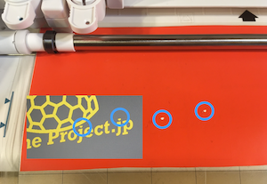
Although not visible in the picture, the dot part of the letter J was skipped.
Probably, a small radius circle does not rotate the blade well.
From next time, I would like to increase the point or adjust the condition and speed with the blade to make the optimal adjustment.

Pretty analog work. A light with a convex lens is a necessity for me with presbyopia.

done! ! ! Very satisfied.
parametric construction kit
- Platonic solid
concept
- Design that can respond freely even if the thickness of the material, the size of the sides of the figure (two regular triangles and squares) (this time set to 60 mm), and the type of laser cutter change.
- Make a kit that can fill the space with two solids, regular tetrahedron and regular octahedron, and experience infinite space expansion.
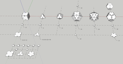
And for me, I wanted to make a Plato 5 solid and a vector equilibrium from before.
First, I created six solids using SketchUp, which I was familiar with, and put together each part.
Convert the part diagram to dxf and export.
Then read it with Fusion360.
Here was the problem.
Error occurred when inserting dxf file of SketchUp 3D model with Fusion360 sketch.
Forced termination of Fusion360.
So, this time, I tried to import with Fusion360 the dxf conversion and export with 2D model instead of 3D model.
Then I was able to read it successfully.

Parametric design
I didn’t really understand the meaning of parametric design until I went to Kamakura on Saturday.
I just thought that the overall dimensions could be reduced or enlarged.
However, in this training, I learned that the true meaning (convenience) of parametric design is that even if any part (even one part) is changed, the whole changes in conjunction with it.
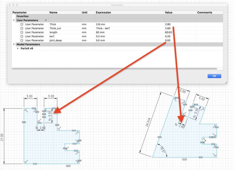
- The parameters were set as follows.
- Thick → Thickness of material
- kerf → kerf
- Thick_cut → Thick-kerf
- length → Equivalent triangle / square side length (common)
- joint_deep → depth of cut
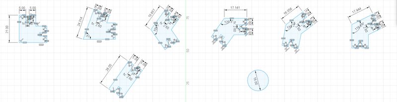
Joint parts

Surface parts
- Test by changing the thickness of the cardboard

OK
- Test by changing the side length to 40 mm
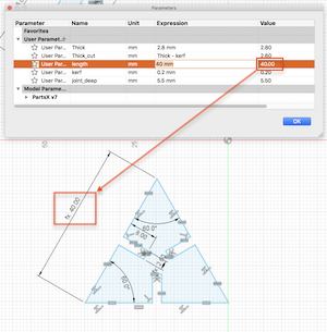
OK
Fusion360 file ginp practice file
Laser cutter
The drawing created in Fusion360 was converted to dxf and read in CorelDRAW.
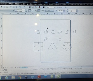
Adjust alignment
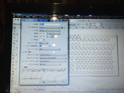
At the time of cutting, the outline color is set to red and the width is set to a very thin line.

Output settings
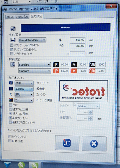
Click the JC button to go to TROTEC JobControlR
Select the job on the right and drop it on the screen to start

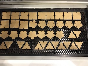
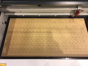
The cut was successfully completed.
Plato 5 solid and vector equilibrium
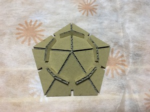

Icosahedron

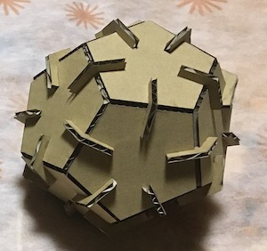
Dodecahedron
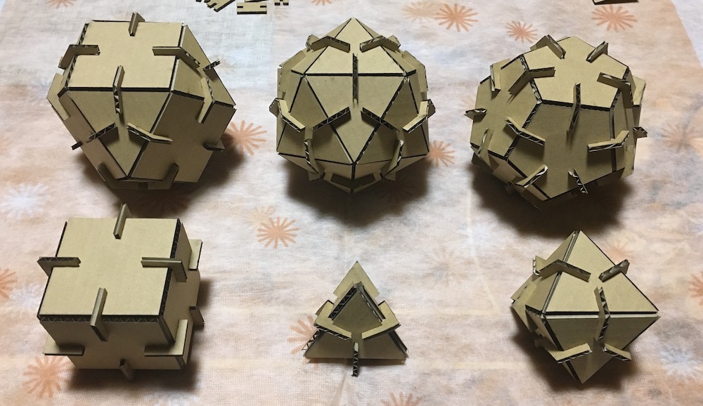
Plato 5 solid and vector equilibrium
- Deformation of vector equilibrium and space filling of tetrahedron and octahedron.
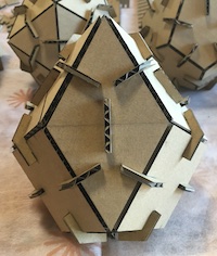
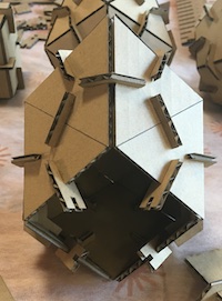
I made an equilateral triangle using a straight joint.
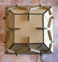
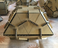


It is shaped like a pyramid.
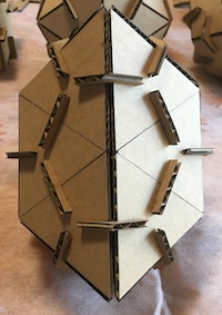
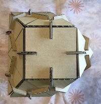
In this way, you can create an infinite space by combining two solids, a regular tetrahedron and a regular octahedron.

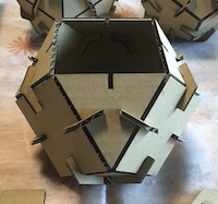
The red arrow is the frame of the dome house generated from the icosahedron.
The red frame is the vector equilibrium included in the regular octahedron.
What I learned this week
-
Sheet cutting with the Cameo vinyl cutter
-
How to use the laser cutter and its settings.