3. Computer-Controlled Cutting#
This is group assignment page of Computer-controlled cutting.
Group Assignment is here.
Group A (Thursday Session)#
Researching on focal point of lasor cutter (Yuki Oka)#
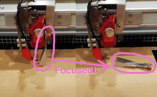
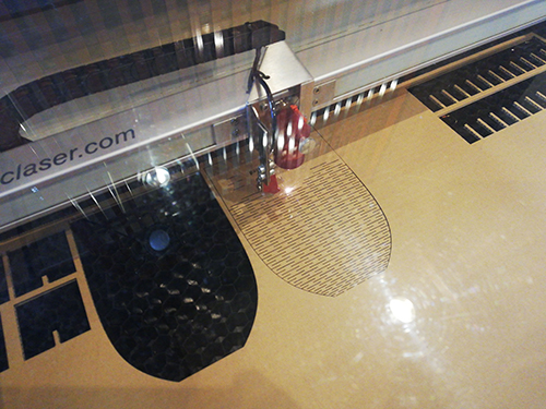
When we use lasor cutter, we have to adjust the fucus of the lasor cutter. There is a metal focus tool for adjusting it. It is used as hooking on the lasor head, and then you gradually move up the table where the material is set. If the material touches the focus tool even slightly, the focus tool falls down and it means the lasor is focused on the material.
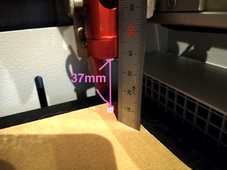
This time, I actually measured the length between the edge of the lasor head and the material surface when the focus was set. It was about 37mm.
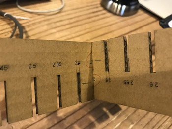
As a test, I tried cutting on the point slightly moved from the focal point. If it is only ±1mm moved(38mm and 36mm), the cutting is processed without problem.
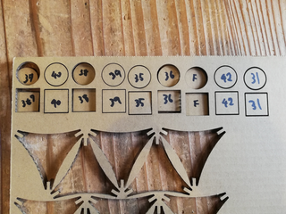
±2mm moved ones(39mm and 35mm) were almost cut but it wasn’t cut out through the material completely. The trials cut more then ±3mm, the lasor couldn’t even reach to the backside. And if the aim point gets farther and farther or closer and closer to the focal point, the trace of the lasor would be getting wider.

the razor moved ±2mm from focal point reaches to the backside. almost!
the razor moved more than ±5mm from focal point cannot cut at all. but its traces of lazor are wide!
Validation of Parameters - Toshiki Tsuchiyama#
I have verified the optimum parameters for cutting a cardboard (thick=3 mm)
1. Use the sample in FabLab Kamakura#
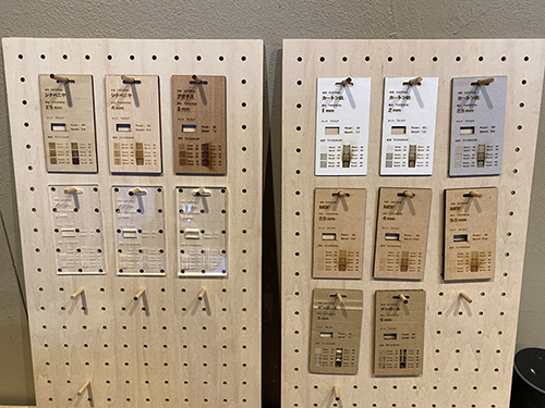
FabLab Kamakura has parameter settings for cutting and engraving for each material.
This is a sample cardboard parameter configuration.
And this is the data I prepared this time.
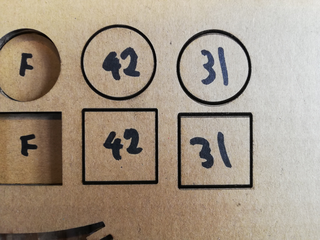
I prepared data to be cut into squares and circles.
The reason for this is that the power required for a straight line and a curved line is slightly different, so both are set to break.
(It’s just preparation from my experience.)
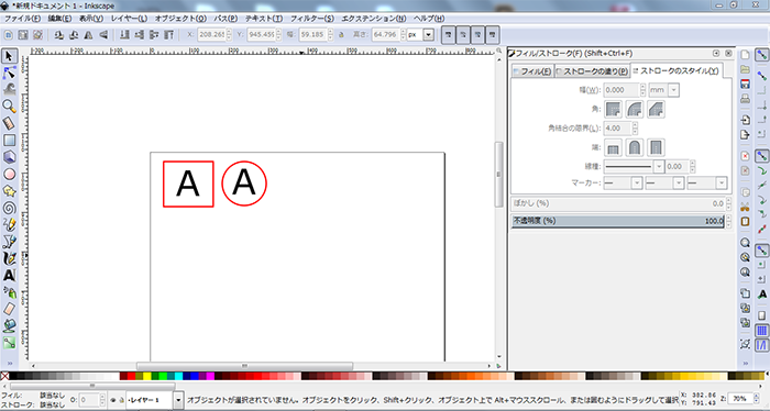
Data created by Inkscape.
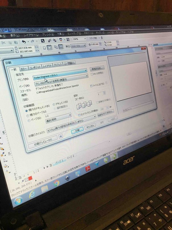
Print→Advanced settings are set like this.
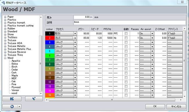
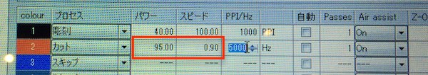
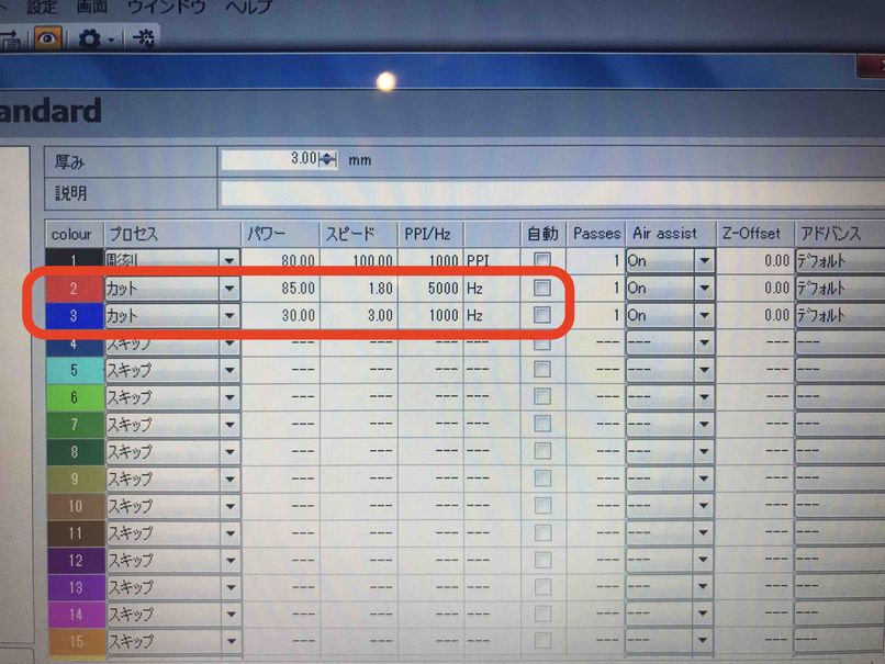
Set parameters in the job control system.
Based on this sample, I set the cut parameter to [Power:85, Speed:1.2],and set the engraving parameter to [Power:85, Speed:90].
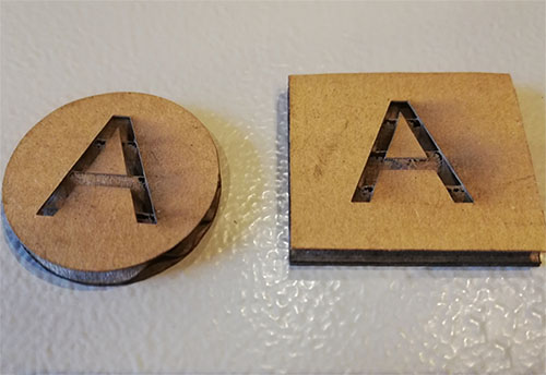
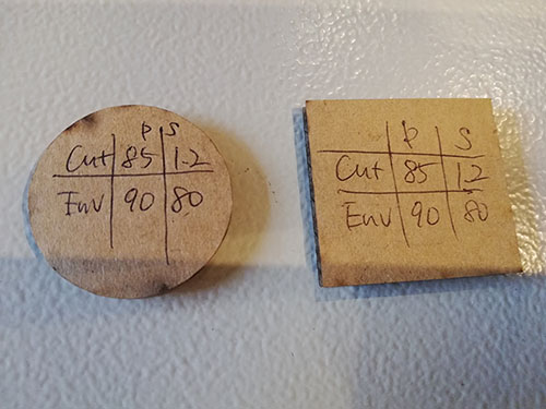
I was able to get through without any problems, but I was bothered by the moss on the back.
I thought about the danger of a fire and looked for parameters that could be cut with minimum power.
2. Verifying Minimum Power#
I didn’t change the speed parameters, and I reduced the power by 10 each.
(The parameters of the sculpture remain the same.)
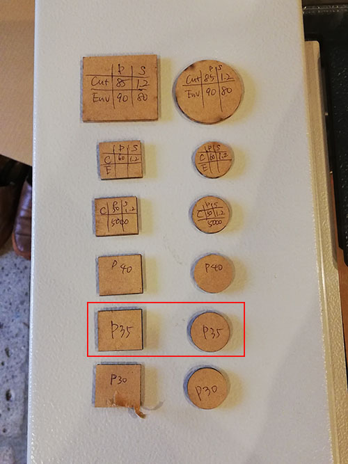
As a result, it was found that [Power:35, Speed:1.2] could cut it.
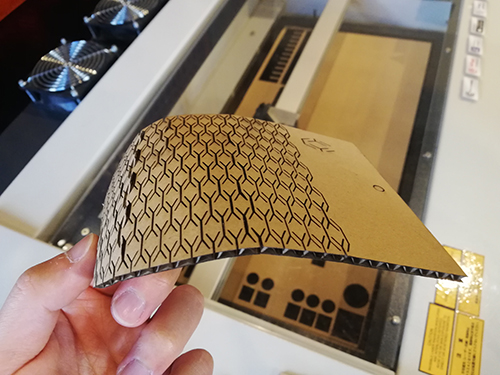
3. Curved Laser Cardboard#
I tried curve machining during group work.
However, I didn’t design the kit because it was difficult to express this design with a parametric.
Designing joints to verify the calculated kerf - Menghe Xu (Yume)#
To test if the kerf we defined is correct and practical, I modeled and cut some joint pieces with the defined kerf.
I took Neil’s 3D CAD data (link) on joints, and modified the parameters of Press-fit joint on FreeCAD.
It started as this:
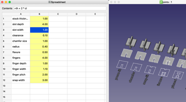
I identified and modified the parameters in the Spreadsheet.
stock thickness: thickness of the cardboard = 3mm
clearance: -1/2 of kerf = -0.175
slot depth: size of the piece = 30mm
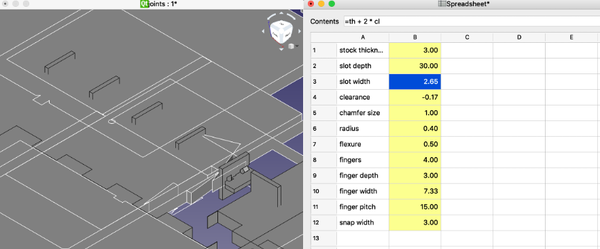
I exported the data as svg, cut 2 pieces and they turn out to fit pretty well!
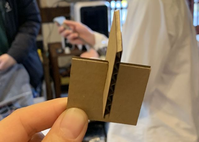
It verifies that the kerf we identified is appropriate.
Another learning outcome is about directly sending data to laser cutter (printing through Trotec’s drive) from Inkscape application.
Choose Trotec’s driver in the print menu, the advanced settings should be like this.
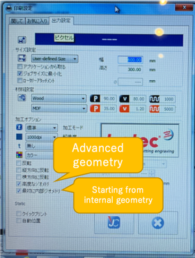
Make sure the canvas is 600*300, and check for geometry settings based on preference. “Advanced geometry” cuts circles in a finer manner. “Starting from internal geometry” simplifies the cutting process and starts the cutting always from the internal geometry.
After the settings, press print and the usual Trotec printing page will show up.
Group B (Saturday Session)#
Laser cutter setting (power / speed) by Hiro-Kimura#
Our Group B first tested with varying power and speed.
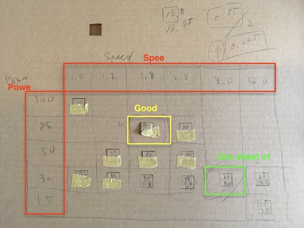
The result was a power of 85 and a speed of 1 and 8 when clipping.
Also, if you want to cut one sheet of paper, it seems better to set at power 30 and speed 3.0.
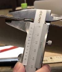
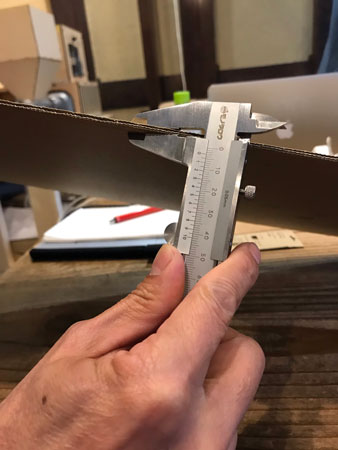
Cardboard thickness is 2.8mm
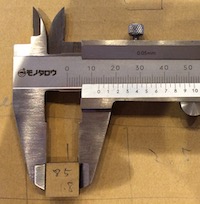
The width of the rectangle is 13 mm
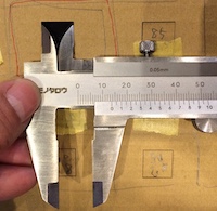
The width of the cut rectangle is 13.5 mm
from this result,
13.5 mm - 13 mm = 0.5 mm
0.5 mm / 2 = 0.25 mm
The dimensions of karv are about 0.25 mm.
How to use Laser Cutter ( by Haru (Oguri) )#
Outline#
4 steps to cut/carve something by laser cutting machine
( trotec Speedy100 at fablab Kamakura )
- step 1 ; data preparation on PC ( Corel DRAW ( Adobe Illustrator can be used )
- step 2 ; “PRINT” from PC
- step 3 ; Laser Cutter boot up ( trotec Speedy100 )
- step 4 ; Cutting/Carving ( trotec Speedy100 + Job Control )
step-by-step details#
step 1 ; data preparation on PC ( Corel DRAW )#
( in case that the data is from fusion360 ( “.dxf” data ) )
-
open the “.dxf” file from Corel DRAW.
-
set the line color as RED ( R:255 / G:0 / B:0 ), line width as GOKU-HOSO ( extremely thin ).
-
set the color of the carving part as BLACK
step 2 ; “PRINT” from PC#
-
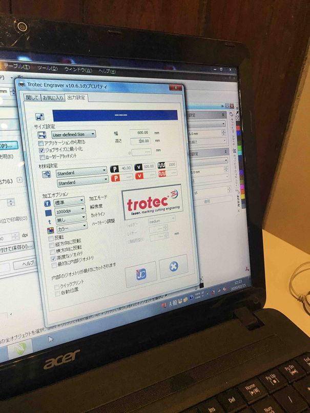
In Corel DRAW, “PRINT” the file, select the “Trotec Engraver” as the printer, in property tab, check “Minimize to jobsize”. Set the canvas as 600mm x 300mm. OK -> Print. ( ” Job Control ” ( printer driver ) starts. )
-
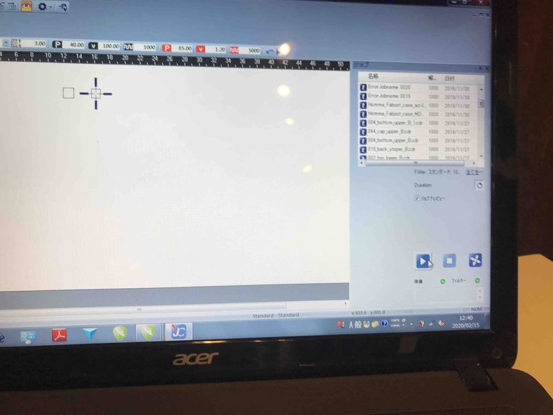
In Job Control, drag the appropriate job from the list ( right area ) to the plate ( left white area ).
-
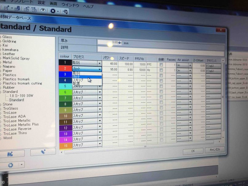
open the “material database ( template )” from setting menu, then apply the appropriate parameters such as POWER, SPEED, PPI/Hz. ( RED color for the cutting, BLACK for carving ) -> OK ( close )
| select the “Trotec Engraver” as the printer | in property tab, check “Minimize to jobsize”. Set the canvas as 600mm x 300mm. |
|---|---|
 |
 |
| drag the appropriate job from the list ( right area ) to the plate ( left white area ) | material database ( template ) |
|---|---|
 |
 |
step 3 ; Laser Cutter boot up ( trotec Speedy100 )#
- turn on the Laser Cutter
( during the starting procedure, the cover of the Laser Cutter should be closed. )
-
After the green-light ( on the operation panel ) turns on, open the cover, then place the material on the grid.
-
move the laser head to the material, then set the focusing gauge on the laser head.
-
adjust the focus by moving up the grid ( push the arrow buttons on the operation panel )
-
move the laser head to the place to be cut/carved.
-
close the cover.
| speedy100 operation panel | set the focusing gauge, adjust the hight of grid |
|---|---|
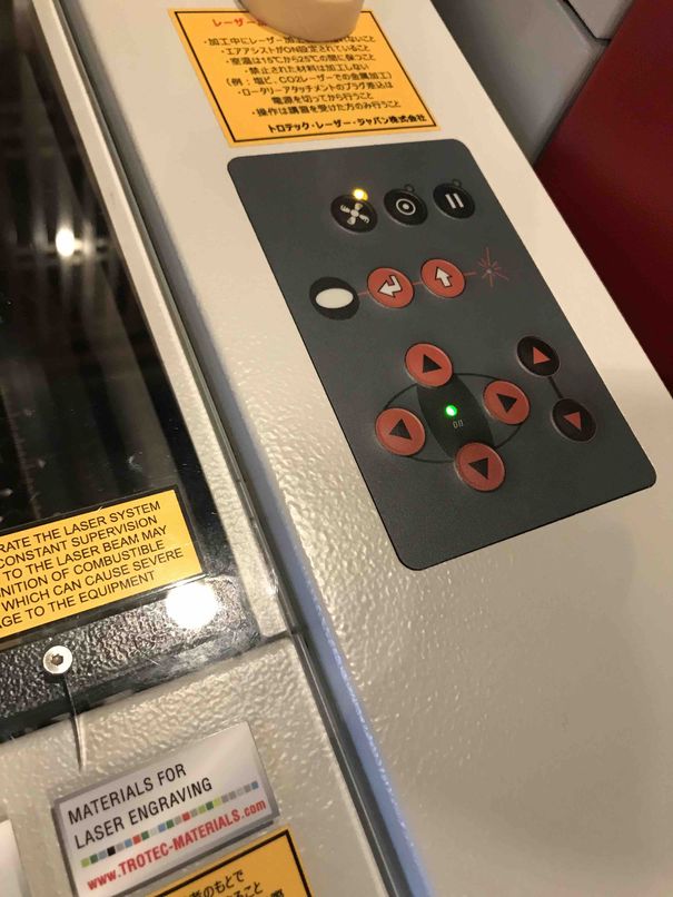 |
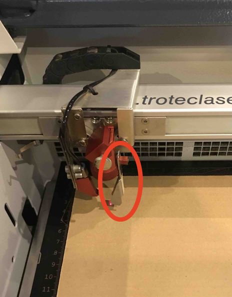 |
step 4 ; Cutting/Carving ( trotec Speedy100 + Job Control )#
-
connect the PC ( Job Control ) with Laser Cutter, by clicking the “connect ” button ( just like USB connector ) in Job Control ( then, plus “+” mark appears in the plate ( left white area ). this shows the position of the laser head.
-
drag the “job” on the plate to the appropriate position. ( this will be snapped to the plus “+” mark )
-
Then, click the start button in Job Control. ( -> Cutting/Carving starts. )
-
after the process completes, move the laser head, then pick up the material.
-
to cut/carve again with the same job file, click the right button on the mouse, then “restart the job”.
| connect the PC ( Job Control ) with Laser Cutter, by clicking the “connect ” button ( just like USB connector ) | drag the “job” on the plate to the appropriate position |
|---|---|
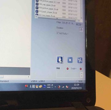 |
|
Tips#
to combine the different kinds of cutting parameters
the parameters can be corresponded to the line colors.
- in Corel DRAW, use RED ( R:255 / G:0 / B:0 ) and BLUE ( R:0 / G:0 / B:255 )
- in Job Control “material database ( template )”, apply the appropriate parameters ( POWER, SPEED, PPI/Hz ) individually, for each colors.
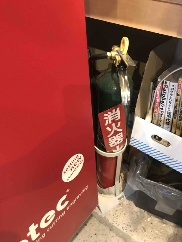
for safety
- during the process, stay close to the Laser Cutter.
| the parameters can be corresponded to the line colors | fire extinguisher |
|---|---|
 |
 |
useful links#
trotec Manuals ( Japanese version )
Optimize the width of joints with a kerf for Press-fit - Kazuki Yanome#
For this part, we optimized the width of joints with a kerf for Press-fit.
Firstly, I checked the thickness of a cardboard. The thickness was 2.80 mm.
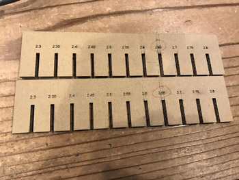
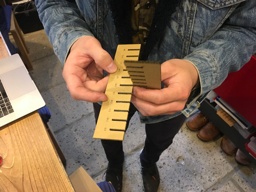
So, for the first try, we tried making twin kits which have 11 joints with 0.01 pitches (width: 2.70 mm - 2.80 mm).
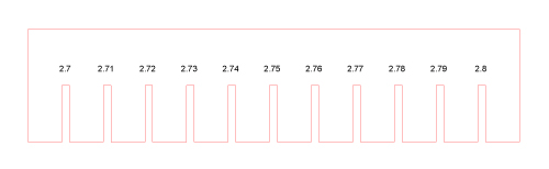
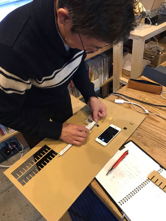
I checked the joints. But even the smallest combination of joints: 2.70 mm x 2.70 mm, it was still a little bit loose.
In parallel, one of my member measured the width of kerf. The kerf was 0.226 mm.
Tip
The kerf should be measured as precisely as possible, because when you decide how much you cut the press-fit width, you can cut it as you refer its value. It helps you shorten your time to decide the width.
Considering the measured kerf, try again with 0.05 pitches (width: 2.30 mm - 2.80 mm).
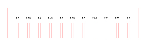
Uhh…
Congratulation! We found out that the best fitted width is 2.65 mm x 2.65 mm. And if you’d like to be more tight fit, it’s okay with 2.60 mm x 2.60 mm.