14.Networking
This week assigment
group assignment:
- send a message between two projects
Group project page
I joined this MQTT testing using my esp32 from my site.
individual assignment:
- design, build, and connect wired or wireless node(s) with network or bus addresses
Raspberry Pi + Satshakit
Wiring
For this week’s assignment, I tried serial communication using GPIO pins on my Raspberry Pi and satshakit.
- Main Board: Raspberry Pi 3 Model B
- Subboard 1: Satshakit(on breadboard)
- Subboard 2: Arduino
This is a combination of the above.
The reason for connecting two Satshakits (Arduino) is that there are five motors to run in the final project, and you need two Satshakits to control them.
Click the link below to go to the final project page.
→ Link to final projectpage
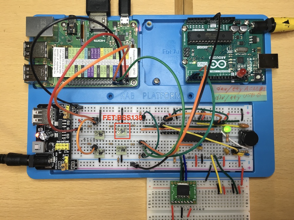
FET(BSS138)
BThe voltage of satshakit is 5 V and the voltage of Raspberry Pi is 3.3 V, so it was necessary to install a voltage conversion module.
I wired two places like the one below.
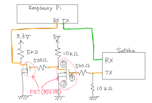
GPIO pin
The UART transmit pin and receive pin are assigned to pin 8 (TXD) and pin 10 (RXD) of the GPIO header, respectively. (GPIO No. 14 and No. 15 pins of SoC)
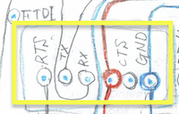
I made a hand-drawn board diagram of the satshakit to connect to the Raspberry Pi.
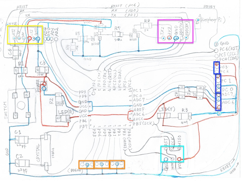
In order to keep it simple when wiring it later, the necessary units I tried to summarize as much as possible.
I’ve created a new breadboard and tested it, but I can’t write to it. Anyway, for a long time I was wondering where the connection was bad, but the cause was simple.
It was good to put together the connection pins of the FTDI cable for writing, but I forgot to put the TX and RX opposite.
-
Before the correction
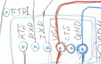
-
Afer the correction
UART setting
1. Disable the Linux serial console.
When Raspbian is installed, the primary UART (/dev/serial0) is used as the Linux serial console. Change it so that it is not used as a serial console in Linux for serial communication.
[Before the change]
pi@raspberrypi:~ $ cat /boot/cmdline.txt
console=serial0,115200
console=tty1 root=PARTUUID=ea7d04d6-02
rootfstype=ext4 elevator=deadline fsck.repair=yes rootwait quiet splash plymouth.ignore-serial-consoles
console=serial0,115200← Delete this item.
[After the chenge]
pi@raspberrypi:~ $ cat /boot/cmdline.txt
console=tty1 root=PARTUUID=ea7d04d6-02
rootfstype=ext4 elevator=deadline fsck.repair=yes rootwait quiet splash plymouth.ignore-serial-consoles
2.Change to use UART0 for serial communication.
In addition to serial communication, if you use Bluetooth, change it to use miniUART to communicate with the Bluetoot module. This makes it possible to use UART0 for serial communication.
Edit the /boot/config.txt file as follows.
pi@raspberrypi:~ $ sudo vi /boot/config.txt

...
dtoverlay=pi3-miniuart-bt  ← Add this line.
...
UART0 (/dev/ttyAMA0) is allocated as the primary UART (/dev/serial0), and miniUART (/dev/ttyS0) is allocated as the secondary UART (/dev/searal1).
pi@raspberrypi:~ $ ls -l /dev

lrwxrwxrwx  1 root root           7  5月 11 19:15 serial0 -> ttyAMA0
lrwxrwxrwx  1 root root           5  5月 11 19:15 serial1 -> ttyS0
...
crw-rw----  1 root dialout 204,  64  5月 11 19:16 ttyAMA0
crw-rw----  1 root dialout   4,  64  5月 11 19:15 ttyS0
...
Next, fix the GPU’s core clock so that the serial communication baud rate does not change.
Edit the /boot/config.txt file as follows.
pi@raspberrypi:~ $ sudo vi /boot/config.txt
...
core_freq=250  ← Add this line.
3.Now, you can perform serial communication using GPIO.
I restarted it just in case.
programming
Raspberry Pi side
Towards the satsha, a program is put out in which the LED flashes 10 times per second.
import serial
import time

ser = serial.Serial('/dev/ttyACM0', 9600)

for i in range(10):
        ser.write('a')
        print("LED ON")
        time.sleep(0.5)
        ser.write('0')
        print("LED OFF")
        time.sleep(0.5)

ser.close()
print("bbb")
Satshakit(Arduino) side
byte val=0;
#define LED_PIN 13

void setup() {
   pinMode(LED_PIN, OUTPUT);
   Serial.begin(9600);
}

void loop() {
   if(Serial.available() > 0){
      val = Serial.read();
   }
   if(val == 'a') digitalWrite(LED_PIN, HIGH);
   else if(val == '0') digitalWrite(LED_PIN, LOW);
}
Then, the chip LEDs on the Arduino base blinked 10 times at 1 second intervals.
In addition, the display of the Raspberry Pi also displayed letters such as “LED ON” and “LED OFF” at the same time as Arduino’s LED ON/OFF.
esp32
-
Enables ESP32-WROOM-32D to be used in the Arduino IDE
-
Get a library from Espressif Systems on GitHub
Enter the following command from a terminal
mkdir -p ~/Documents/Arduino/hardware/espressif && \
cd ~/Documents/Arduino/hardware/espressif && \
git clone https://github.com/espressif/arduino-esp32.git esp32 && \
cd esp32 && \
git submodule update --init --recursive && \
cd tools && \
python get.py
- Launching the Arduino IDE
- Select “Tools” - “Boards” - “ESP32 DevModule”.
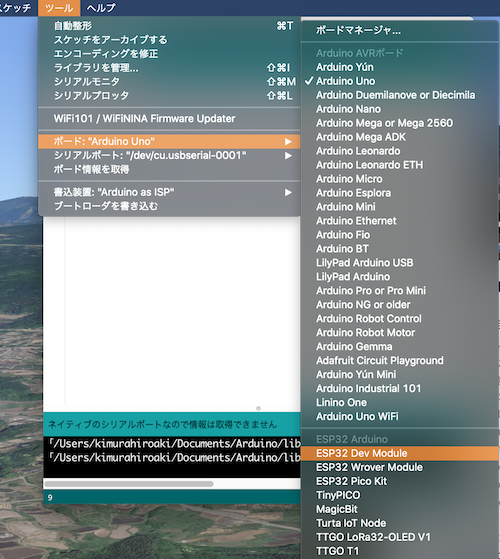
- Install the serial driver.
Serial Driver Download Page

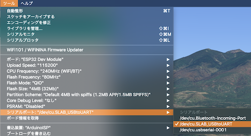
–> Arduino IDE reboot
Select “Tools” - “Serial Port” - “/dev/cu.SLAB_USBtoUART” because it is newly created.
-
programming
-
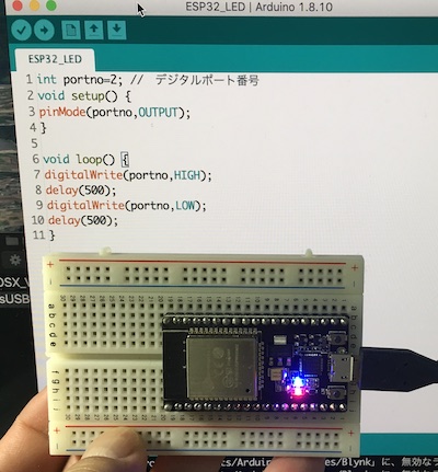
LED test
int portno=2; // デジタルポート番号
void setup() {
pinMode(portno,OUTPUT);
}

void loop() {
digitalWrite(portno,HIGH);
delay(500);
digitalWrite(portno,LOW);
delay(500);
}
Tool Settings
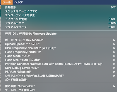
The LED of the main body of esp32 blinked at one second intervals.
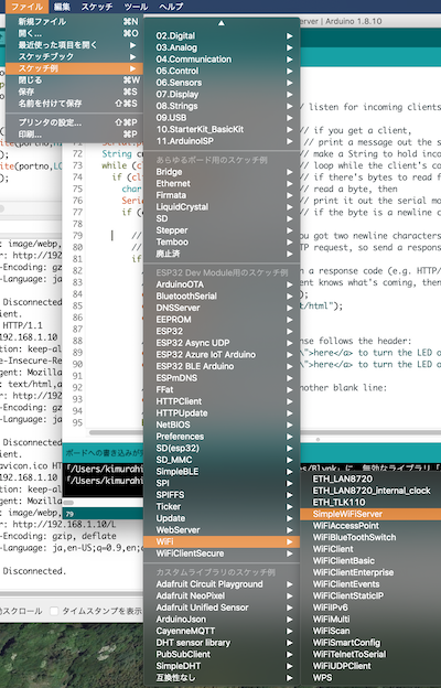
- Wi-Fi
I instruct the LED of the next test circuit which did L-Tica last time from PC via Wi-Fi and try to blink. Using the ESP32 sample program for this experiment, we will turn on and off the I/O port of the microcontroller (ESP32-WROOM-32D) from a PC via Wi-Fi.
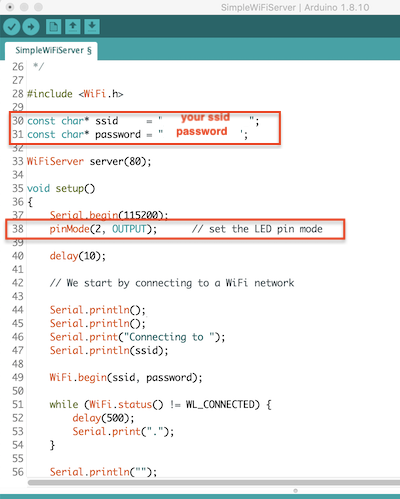
Load the sample program SimpleWiFiServer.
Write the SSID and password.
The pin mode is set to No. 5 by default, but it changed to the pin mode No. 2 of the LED attached to the main body of esp32.
Tool Settings
When the serial monitor is started, the program is started as soon as the writing of the program is completed, and the following message is displayed on the serial monitor.
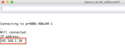
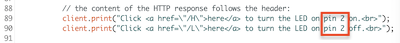
When you access the IP address assigned to ESP32-WROOM-32D by typing http://192.168.1.10 in the URL field of your PC’s Web browser, the following message will appear.
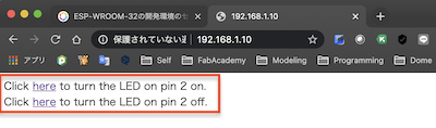
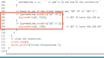
When you click here in the message at the top, the LED will light up. When you click this here, a message of /H is sent from the PC to ESP32-WROOM-32D, and when the letter /H is detected, port 5 is set to HIGH so that the LED lights up.
Click the link below to go to the final project page.
→ Link to final projectpage