11.Output device
This week assigment
group assignment:
- measure the power consumption of an output device
Group project page
individual assignment:
- add an output device to a microcontroller board you’ve designed,
and program it to do something
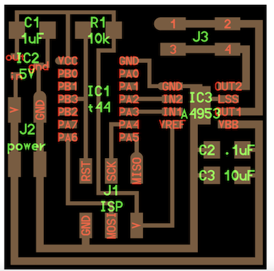
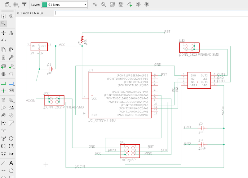
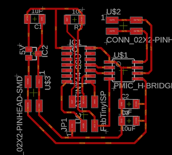
Board Design
I used the board for the DC motor (hello.H-bridge.44 ) as a reference to tackle the task.
Because there are plans to use a DC motor to open and close the windows in the final project.
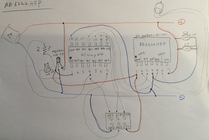
This time, I tried to draw a diagram by connecting it to the actual wiring.
The lab in Kamakura is closed again this week.
So I created it using a breadboard.
Before that, I drew the wiring diagram for the breadboard again by hand.
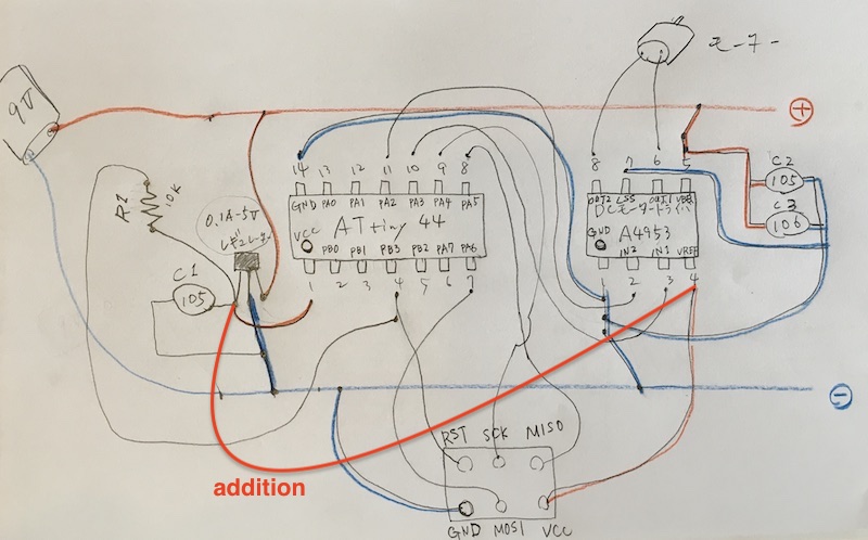
A single wire was missing, which has been corrected.
You can see it better when you draw it by hand.
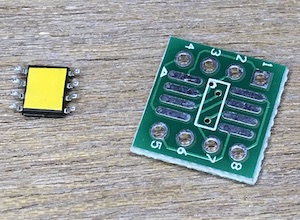
The dc motor driver uses the A4953.
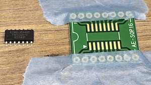
Solder the breakout board so that it can be assembled on the breadboard.
Before soldering, the instructor instructed me to put insulating tape on the back side to prevent a short circuit.
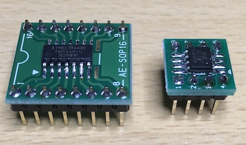
I also soldered ATtiny44.
It was the first time I had ever soldered a breakout board, but I thought I did well.
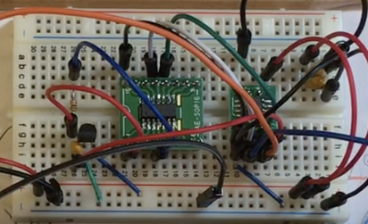
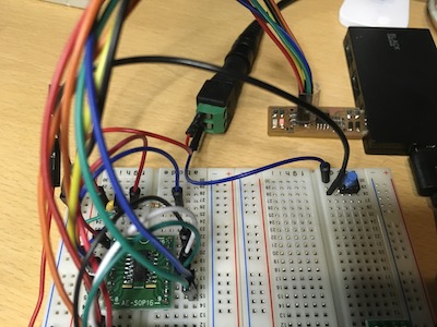
It’s too crowded to see well, but the wiring is done.
Programming
I wrote the program using the FabTinyISP I created in week4.
make -f make file command
$ make -f hello.H-bridge.44.DC.make

avr-gcc -mmcu=attiny44 -Wall -Os -DF_CPU=8000000 -I./ -o hello.H-bridge.44.DC.out hello.H-bridge.44.DC.c
avr-objcopy -O ihex hello.H-bridge.44.DC.out hello.H-bridge.44.DC.c.hex;\
    avr-size --mcu=attiny44 --format=avr hello.H-bridge.44.DC.out
AVR Memory Usage
----------------
Device: attiny44

Program:     464 bytes (11.3% Full)
(.text + .data + .bootloader)

Data:          3 bytes (1.2% Full)
(.data + .bss + .noinit)
program-usbtiny-fuses → Error
$ sudo make -f hello.H-bridge.44.DC.c.make program-usbtiny-fuses

Password:
make: hello.H-bridge.44.DC.c.make: No such file or directory
make: *** No rule to make target `hello.H-bridge.44.DC.c.make'.  Stop.
I’m going to try and pull out the .c → Error
$ sudo make -f hello.H-bridge.44.DC.make program-usbtiny-fuses

make: *** No rule to make target `program-usbtiny-fuses'.  Stop.
Checking the contents of the .make file, there is no file notation for -fuses → (has the -fuses already been completed?)
Because there’s a no-directory and an error.
So, you can skip the -fuses and run make progrom.
Success!
$ sudo make -f hello.H-bridge.44.DC.make program-usbtiny
Password:
avr-objcopy -O ihex hello.H-bridge.44.DC.out hello.H-bridge.44.DC.c.hex;\
    avr-size --mcu=attiny44 --format=avr hello.H-bridge.44.DC.out
AVR Memory Usage
----------------
Device: attiny44

Program:     464 bytes (11.3% Full)
(.text + .data + .bootloader)

Data:          3 bytes (1.2% Full)
(.data + .bss + .noinit)


avrdude -p t44 -P usb -c usbtiny -U flash:w:hello.H-bridge.44.DC.c.hex

avrdude: AVR device initialized and ready to accept instructions

Reading | ################################################## | 100% 0.01s

avrdude: Device signature = 0x1e9207 (probably t44)
avrdude: NOTE: "flash" memory has been specified, an erase cycle will be performed
         To disable this feature, specify the -D option.
avrdude: erasing chip
avrdude: reading input file "hello.H-bridge.44.DC.c.hex"
avrdude: input file hello.H-bridge.44.DC.c.hex auto detected as Intel Hex
avrdude: writing flash (464 bytes):

Writing | ################################################## | 100% 0.79s

avrdude: 464 bytes of flash written
avrdude: verifying flash memory against hello.H-bridge.44.DC.c.hex:
avrdude: load data flash data from input file hello.H-bridge.44.DC.c.hex:
avrdude: input file hello.H-bridge.44.DC.c.hex auto detected as Intel Hex
avrdude: input file hello.H-bridge.44.DC.c.hex contains 464 bytes
avrdude: reading on-chip flash data:

Reading | ################################################## | 100% 0.85s

avrdude: verifying ...
avrdude: 464 bytes of flash verified

avrdude: safemode: Fuses OK (E:FF, H:DF, L:62)

avrdude done.  Thank you.
Debugging
But for some reason, the motor does not turn.
- I checked the voltage of ATtiny’s PA2/PA3 and motor driver A4953 with an oscilloscope, and the programming seems to be working properly as far as the waveform is concerned.
- Next, I checked the motor and it turned fine.
- I checked the corner parts and wiring once and they are connected without any problems.
- The rest of the possibilities are that the motor driver A4953 is faulty or that it was poorly soldered?
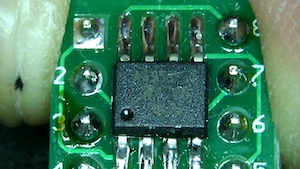
- As far as checking with Digital Microscope, no mistakes could be found.
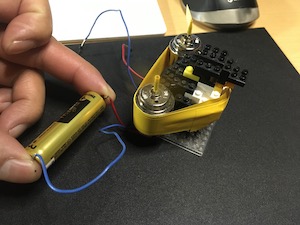
So far, I’ve decided to replace it with a new motorized puller bar.
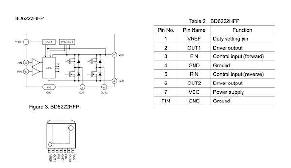
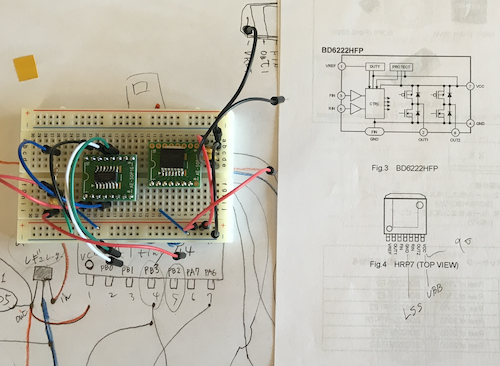
BD6222HFP
I had a “BD6222HFP” at home that I had purchased for my final project, so I decided to use it.
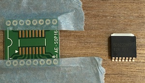
The BD6222HFP is capable of delivering a voltage of 6 to 15 volts and a current of 2A to the motor in this small size.
Soldering to the Breakout board is now complete.
1.VREF - power control for motors (3 ~ 15v)
2.OUT1 - Output terminal to motor
3.FIN - combined with RIN to input signals for rotation, reverse rotation, stop, brake, etc.
4.GND - Ground
5.RIN - combined with FIN to input signals for rotation, reverse rotation, stop, brake, etc.
6.OUT2 - Output terminal to motor
7.VCC - Power input for motor drivers (6 to 15v)
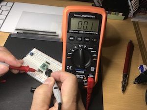
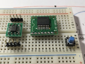
First, I made a simple circuit to check the movement of the motor driver.
- Blue switch button, 3.FIN. The red switch button is connected to the 5.RIN.
- 7.VCC to 1.VREF uses 100Ω as a resistor.
I found from this test that the FIN is positive and the RIN is reversed. Also, the switch between forward and reverse rotation is instantaneous.
Next, I replaced the switch with an Arduino, which allows the program to control the motor to stop or reverse rotation in a certain time.
The following program repeats rotation → pause → reverse rotation → pause every one second.
int leftP   = 10; // connect 3.FIN
int rightP  = 9; // connect 5.RIN
void setup() {
pinMode(leftP, OUTPUT);
pinMode(rightP, OUTPUT);
}
void loop() {
digitalWrite(leftP, HIGH); // FIN-ON
digitalWrite(rightP, LOW);
delay(1000);
digitalWrite(leftP, LOW);
digitalWrite(rightP, LOW);
delay(1000);
digitalWrite(leftP, LOW);
digitalWrite(rightP, HIGH); // RIN-ON
delay(1000);
digitalWrite(leftP, LOW);
digitalWrite(rightP, LOW);
delay(1000);
}
Board Design_BD6222
I decided to make a drawing of a new board using the BD6222HFP.
However, there was no data of “BD6222HFP” in the library of eagle, so I searched on the Web and down-rooted it.
(Note, you had to register for an account in order to download.)
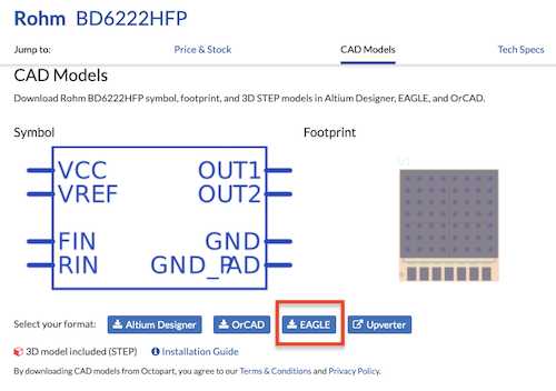
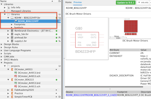
I unzipped the zip file I downloaded and moved it to the Eagle’s library folder.
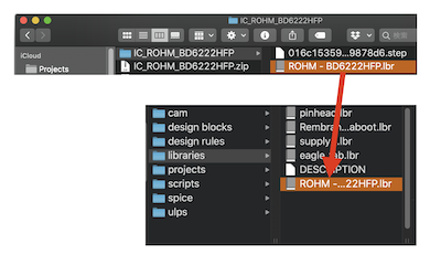
It is reflected in the library without any problems.
Next, I wrote a schematic in Eagle.
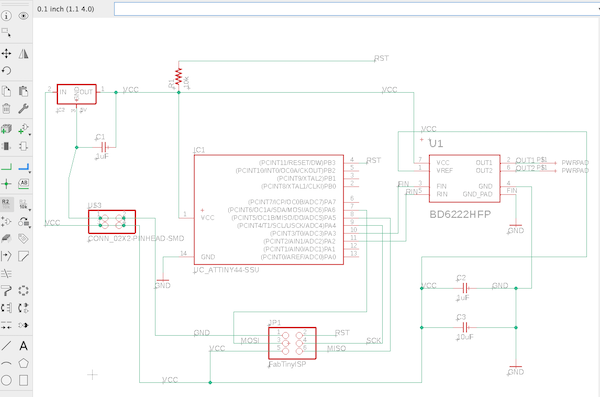
Eagle data : DCmorter_A4953.sch
But the GND wiring doesn’t connect......... I’ll keep that as an issue for next time.
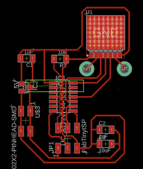
Eagle data : DCmorter_A4953.brd
As usual, I wrote the schematic by hand.
Working on a breadboard.
Commissioning and measurement
The wiring is complete.
It worked fine.
The movements of the motor were low speed forward and reverse, medium speed forward and reverse, and high speed forward and reverse.
When I measured the output with an oscilloscope, the high and low waveforms seem to be 1:1, 1:1.5, and 1:2.
I actually wanted to rewrite the C code and try various things, but suddenly the microcomputer broke down and did not work normally, so I would like to do this again next time.
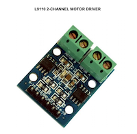
L9110S Test
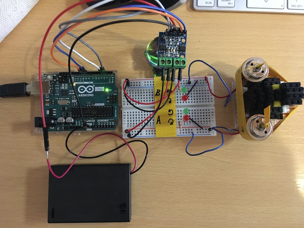
The lab in Kamakura is closed, so they mailed me a class kit instead. I also tried the motor driver that was in it.
We could visually confirm that the H-bridge controlled the forward and reverse rotation of the current flow by the alternating red and green flashes of the LEDs.
const int A1A = 2;//define pin 2 for A1A
const int A1B = 3;//define pin 3 for A1B

const int B1A = 8;//define pin 8 for B1A
const int B1B = 9;//define pin 9 for B1B

void setup() {
  pinMode(B1A,OUTPUT);// define pin as output
  pinMode(B1B,OUTPUT);

  pinMode(A1A,OUTPUT);
  pinMode(A1B,OUTPUT);
  delay(3000);
}

void loop() {

  motorA('R');// Turn motor A to RIGHT
  delay(2000);
   motorA('L');// Turn motor A to LEFT
  delay(2000);
  motorA('O');// Turn motor A OFF
  delay(2000);

  motorB('R');// Turn motor B to RIGHT
  delay(2000);
   motorB('L');// Turn motor B to LEFT
  delay(2000);
  motorB('O');// Turn motor B OFF
  delay(2000);

  motorA('R');// Turn motor A to RIGHT
  motorB('R'); // Turn motor A to RIGHT
  delay(2000);
  motorA('L');// Turn motor A to LEFT
  motorB('L');// Turn motor B to LEFT
  delay(3000);
  motorA('O');// Turn motor A OFF
  motorB('O');// Turn motor B OFF
  delay(5000);

}

/*
 * @motorA
 * activation rotation of motor A
 * d is the direction
 * R = Right
 * L = Left
 */
void motorA(char d)
{
  if(d =='R'){
    digitalWrite(A1A,LOW);
    digitalWrite(A1B,HIGH);
  }else if (d =='L'){
    digitalWrite(A1A,HIGH);
    digitalWrite(A1B,LOW);
  }else{
    //Robojax.com L9110 Motor Tutorial
    // Turn motor OFF
    digitalWrite(A1A,LOW);
    digitalWrite(A1B,LOW);
  }
}// motorA end


/*
 * @motorB
 * activation rotation of motor B
 * d is the direction
 * R = Right
 * L = Left
 */
void motorB(char d)
{

    if(d =='R'){
      digitalWrite(B1A,LOW);
      digitalWrite(B1B,HIGH);
    }else if(d =='L'){
      digitalWrite(B1A,HIGH);
      digitalWrite(B1B,LOW);
    }else{
    //Robojax.com L9110 Motor Tutorial
    // Turn motor OFF
      digitalWrite(B1A,LOW);
      digitalWrite(B1B,LOW);
    }

}// motorB end 00