7. Computer-Controlled Machining#
FabLab Hamamatsu#
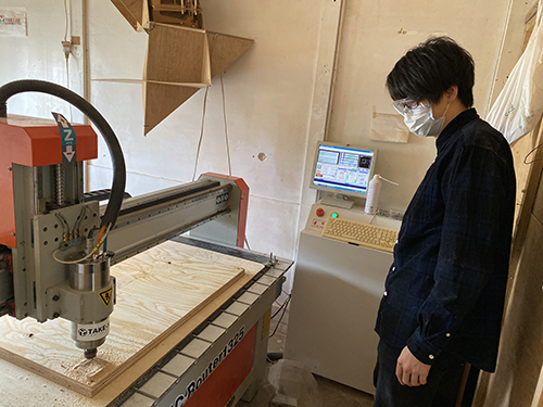
4 of us went to FabLab Hamamatsu to use CNC Router ZN1325.
CNC workflow#
- make 2D/3D CAD file
- make CAM-toopath ( by Cut2D, etc ), setting the tool (mill) information and “tabs” to support the material
- fix the material (wooden plate) on the bed of CNC
- set x-y origin at the corner of the material ( or any other appropriate position ), and set z-origin about 20 mm above the material surface, then, perform “air path” to check the tool path on CNC.
- set z-origin on the material surface ( by using paper to check the contact between tool tip and the material )
- start milling ( be prepared to push the stop button, in case of emergency )
- during the milling, check the wooden chips and the noise, then control the parameters such as feed rate, spindle speed, etc.
- after the milling completed, clean the material surface ( after moving the tool to the safe place, then “Jog OFF” )
- cut the “tabs”, pick up the parts.
- remove the material and sacrifice plate, then clean the CNC and room.
Oka#
I checked the runout of the machine we used especially in the case of using OSB plywood.
for testing I used the parameter below
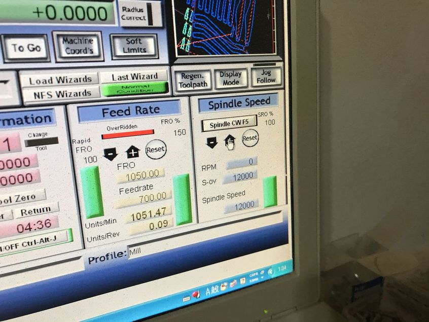
feed rate: 700, spindle speed 12000
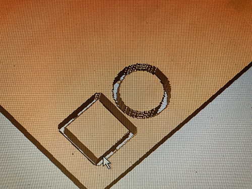
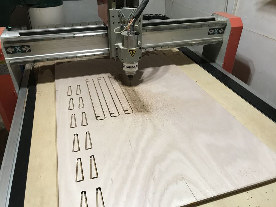
firstly, tried pocket toolpath for cutting simple alphabet shape
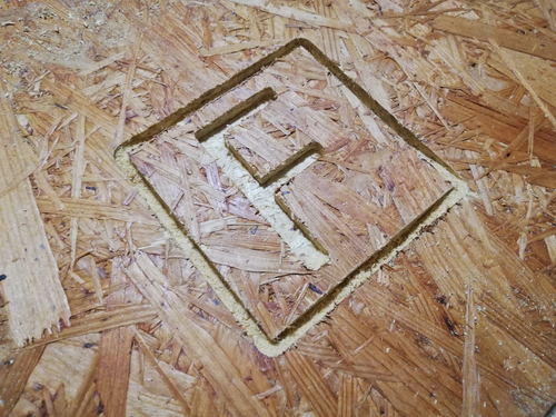
at that time, chose conventional cut. it worked but the edge seemed rough
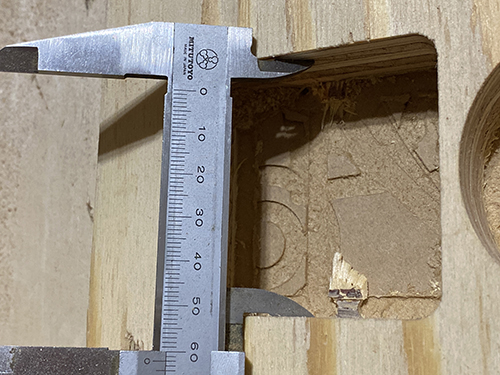
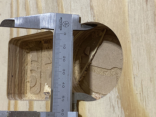
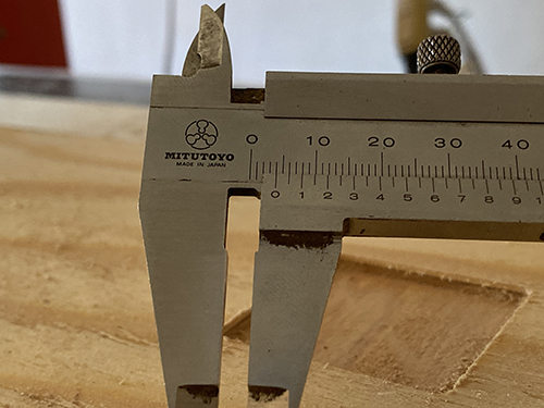
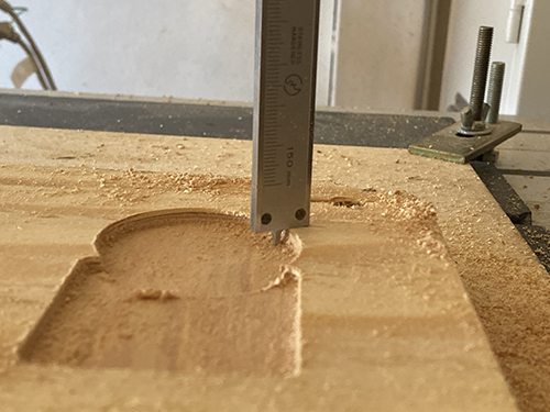
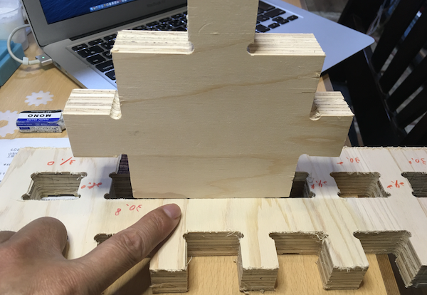
next, I tried the shape which I was going to cut for my work and checked how much material would lost unexpectedly by cutting (checking runout).

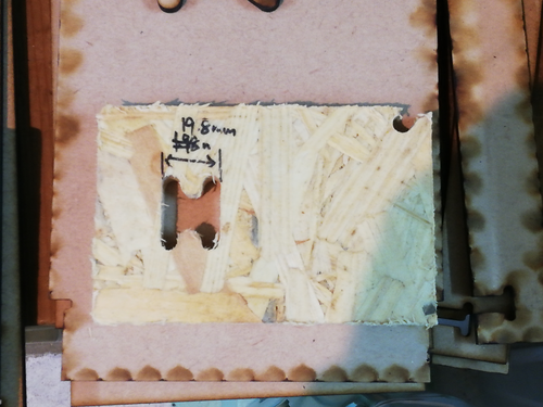
results
| expected | actual |
|---|---|
| 60mm | 59.3mm |
| 12mm | 11.9mm |
| 20mm | 19.8mm |
from the results, it seemed it losted about 0.1mm each time the length of shape was added 10mm though I have no idea with the reason of this mechanism…
Test Cut & Verification of Kerf (Tsuchiyama)#
(1) Data Creation#
This time, I created the data for the test cut in Adobe Illustrator.
I have prepared two types of data for cutting and engraving.
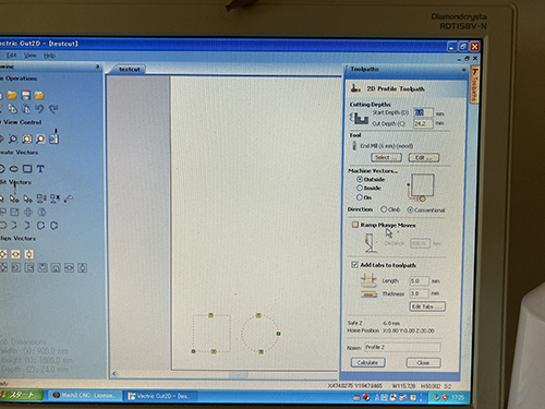
Create a G code in Vector Cut2D and load it into MACH3 CNC Software.
(2) Cutting#
The material I used was [24mm thick softwood plywood].
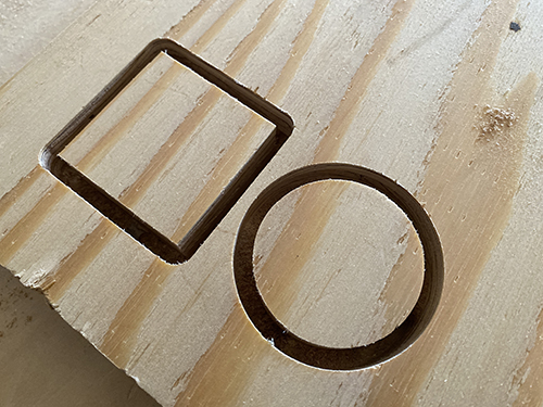
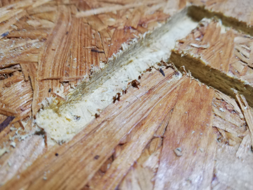
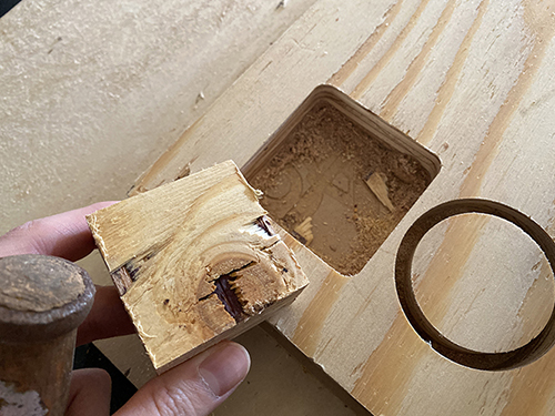
The surface was cut beautifully, but the burr on the back was terrible.
(3) Removal#
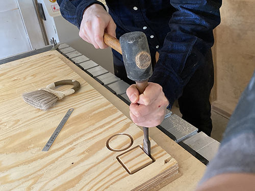
(4) Verification of Kerf#
- W = 50.5mm / H = 50.5mm・・・Kerf = 0.25mm
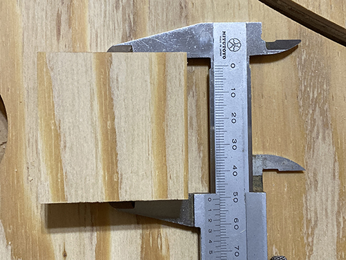
- W = 50.5mm / H = 50.5mm・・・Kerf = 0.25mm
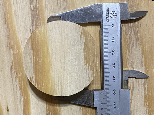
- W = 62mm / H = 62mm・・・Pocket = 1mm
- W = 61.5mm / H = 61.5mm・・・Pocket = 0.75mm
(5) Verification of Engraving#
Reading G-Code
Engraving set at 2mm
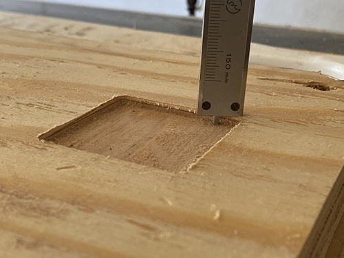
- D = 4mm・・・Difference = 2mm
Engraving set at 3mm
- D = 4.4mm・・・Difference = 1.4mm
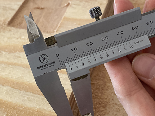
(6) Result#
As a result of verification, it was found that the cutting process produces a kerf of about 0.25 mm.
In addition, the result of engraving was very difficult to verify.
Since the origin position of the Z axis is set to be 2mm deeper than the surface of the material, it was understandable that the engraving of [Depth 2mm] that was machined first resulted in 4mm.
However, I couldn’t understand that the next [depth 3mm] engraving was 4.4mm.
Perhaps the height of the material depends on the position.
The table is parallel to the XY axes, but the height of the Z axis may have changed due to the MDF, which is a waste plate, and the [softwood plywood], which is the processing material, being along.
Oguri#
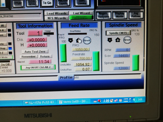
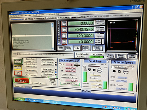
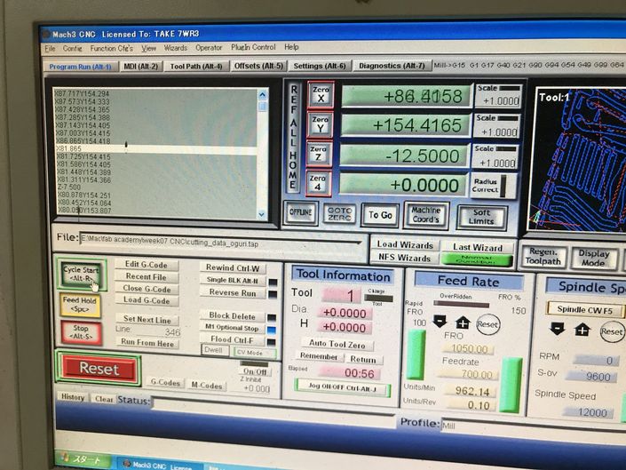
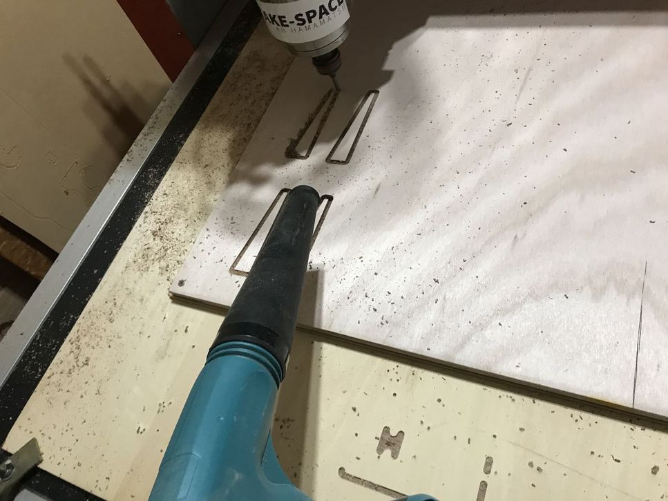
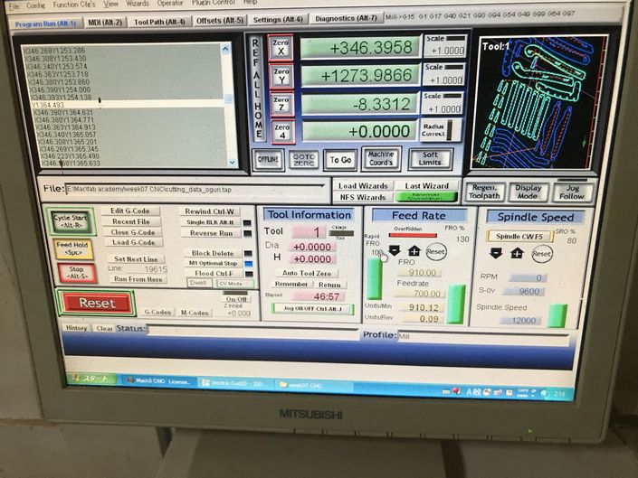
During the cutting process, “feed rate” and “spindle speed” were adjusted, and the wood chips and machine noise were observed.
material : falcata plywood 12 mm thickness
| start milling by pushing the “cycle start” button (left part of the window), feed rate :150%, spindle speed : 80% |
in this case,,, feed rate 100% = 700 rpm spindle speed 100% = 12000 rpm |
|---|---|
 |
 |
| parameter change feed rate :150%, spindle speed : 100% |
chips became a little finer (above ) |
|---|---|
 |
 |
| parameter change feed rate :130%, spindle speed : 100% then, machining noise was a little reduced. |
|
|---|---|
 |
 |
Yume#
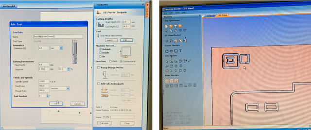
Before actually cutting the plywood, I tested the cut of joints with dog bones.
The set up was:
- Cut depth - 24.5mm (deeper than the wood’s actual dimension to ensure it is cut properly)
- Pass depth - 6mm (I didn’t know you should keep the depth in between half to 1 time of the mill’s diameter)
- Machine vectors - outside
- Spindle speed - 12000rpm
- Feed rate - 700mm/min
- Plunge rate - 300mm/min
- Tab length - 5.0mm
- Thickness - 4.0mm
The parts were nicely cut! And the 2 parts fit.
However, the tabs were too small that one broke before I applied any force.
And the cut went pretty deep into the sacrifice wood.
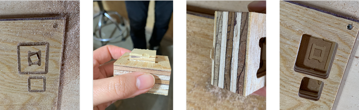
So I decided to set the cut depth to 24.2mm, increased tab thickness to 6mm, increased tab length to 7mm, and added more tabs.
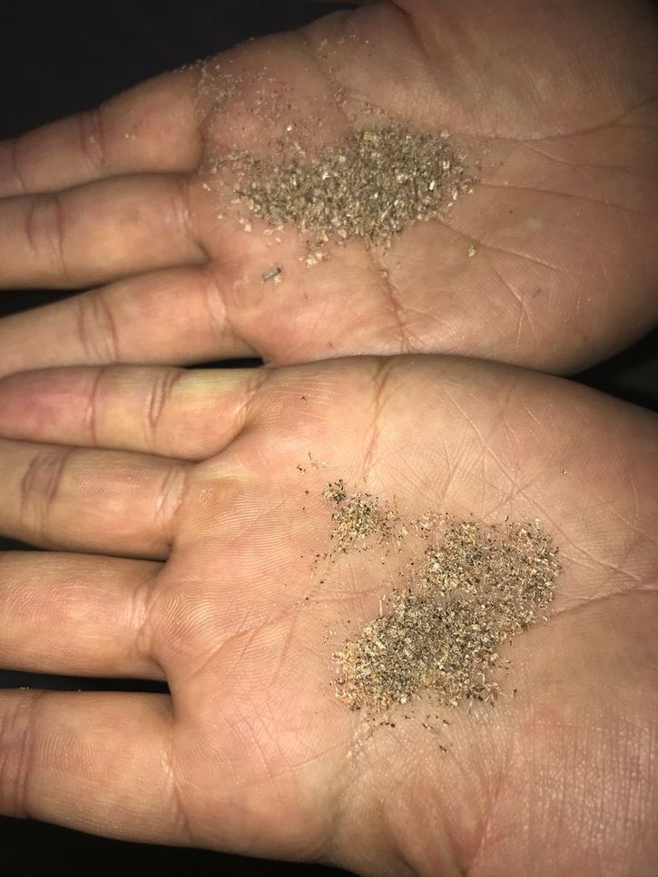
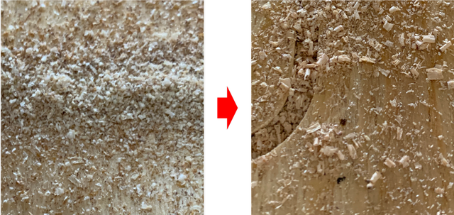
When cutting, instructor Take-san taught me to tell if the speed is appropriate by looking at the sawdust.
At first, my sawdust was very fine, which means I could raise the speed to have more coarse sawdust.
The left is with 70% of feed rate, and right is with 150% of feed rate.
FabLab Nagano#
Kimura#
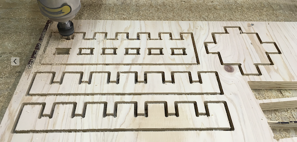
With Janome, I checked the combination of the joints at a pitch of 0.2 mm !
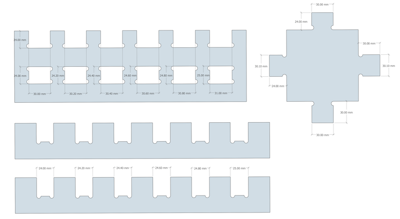
I set the CNC cutting settings for this time to Speed-12000, Feed Rate-1080, and Pass-6time. I was able to reduce the machining time from last time by about 40 minutes.
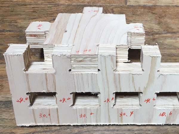
The clearance of 0.3 mm in each direction for the joint of the holes enclosed in the four directions The clearance in each direction is 0.3mm.
However, if you want to assemble it tightly, 0.2mm clearance is fine.
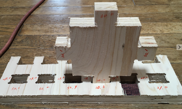
Next, for a hole joint that is enclosed in three directions, the clearance between the two directions is 0.1 mm It looked just fine.
If you want a tighter assembly, the same dimensions (30mm) of zero clearance were fine.
Finally, by taking the direction of the dog bone in the intended direction, there is no half-circle of dog bone in the joint, and I thought it would be neat to look at.
Yanome#
For group assignment, I confirmed to change the feed rates.
Actually, I had a little time to mill because we faced a lot of problems before milling properly. So I checked those conditions with our final object.
The detail of how to use CNC router is described in my week7 page.
So we tried changing the below conditions;
||Feed Rate (mm/min)|Milling Speed (mm/min)|Spindle Speed(rpm)| |—|—|—| |Condition 1|500|272|9000| |Condition 2|700|1200|12000| |Condition 3|1200|3600|12000|
* Feed rate is the speed of moving the pass of an endmill without milling whereas Milling speed is the speed of moving the pass of an endmill with milling.

We first started milling with condition 1 where feed rate: 500 mm / min, milling speed: 272 mm/min, Spindle speed: 9000 rpm, but it took too long time to mill. Condition 2 got a good quality of the milling side of the material, but it took a little bit too time, too. Condition 3 is our best condition though the cutting sound was so big and noisy.
Condition 1 - Slow Milling Speed
Condition 3 - Best condition
I planed to make one of the parts in my final project this week but I’ve not finished my final object completely this week. I need to continue to make it later. So this group assignment will help me make it more speedy.