7. Computer Controlled Machine

Assignments
group assignment:
- Test runout, alignment, speeds, feeds, and toolpaths for your machine.
individual assignment:
- Make (design+mill+assemble) something big.
X. Group Assignment
Link to group session page.
X. Individual Assignment
Materials
- Wood: Veneer plywood (Hiroaki Kimura prepared this material.)
(H:1860 x W:910 x T:24 mm) x 3 pcs

Tools
-
CNC Router: ELE1212
-
Software to make a G code: Cut2D
-
Driver for CNC router: Mach3 CNC
-
Measuring Tape

1. Design a model
From the design of week02, I added some revisions:
- Decide the actual sizes of the table.
- Designed with Parametric Design.
- Reinforced the table with some support parts.
■ Parametric Design
Prametric design is so powerful process that enables us to change the size of your design with keeping its aspect ratio. By setting the valuable to each part of your design, you can change its size with changing the valuable value.
I set the valuables to each part of my design.

Firstly, I wanted to design the vertical and horizontal sizes of the leg parts with a certain ratio.
So I set the parameters to leg parts like this;

The value of the parameter: Leg_Height is given as 3 times of the parameter: Leg_Width2. To do so, if you change the Leg_Width2’s size, the Leg_Height’s value is also changed with the certain ratio.
The first design of my leg with the parameters shown in the above image is like this;

Oh, that’s too small for me. so I changed the size of Leg_Width2 from 100 mm to 200 mm, which means that Leg_Height becomes 600 mm due to its expression with Leg_Width2 x 3.

The revised design is below;

Yes, that’s what I wanted!!
■ Support parts
Got the advice from Kimura-san who is one of the student in Fab Academy, I added the support parts to make it strong against shaking as below;


To mill the place where the support part are inserted, it needs to make the dogbone at the corner of that place because the corner of the milling part becomes as round as the radius of a endmill.

To add the dogbone at the corner, its 90 angles is kept.

Failure
Importance of adding dogbone
I forgot to add dogbones to the joint part of the leg parts with the top board. So I needed to sharpen the corners by my own hand. That was very tough and waste my time a lot. And finally, my leg got dirty with wood chips…


Tips
Projection
To save as .dxf file, you need 2D sketch of your 3D model. For Fusion360, Projection is the useful feature.
Go to Create Sketch and select the plane you’d like to project 2D sketch. And then, go to Create -> Project/Include -> Projection. The purple line in the below image shows projected 2D sketch.

2. Create a G code from .dxf file
Saved my models as .dxf file and open it with Cut2D.
Set the sizes (Height, Width, Thickness) of the material that I set and the origin point.
If you’d like to mill with the different milling conditions every milling route, it is needed to set the milling conditions (e.x. Feed Rate or Number of Pass) every milling route. I separated the pass with inner and outer milling and set the conditions separately.
Added tabs to fix the cut parts as that parts cut off.
You can change to the size of a tab with length and thickness.

| Spec. | Condition 1 | Condition 2 |
|---|---|---|
| Milling thickness (mm) | 25.0 | 25.0 |
| Radius of End Mill (mm) | 6 | 6 |
| Rotation Speed of endmill (rpm) | 12000 | 12000 |
| Feed Rate (mm/min) | 500 | 500 |
| Milling Process | Outer | Inner |
| Pass (times) | 9 | 9 |
Failure
The models aren’t closed completely
If there are the unclosed parts in your 2D sketch, G code cannot be created. So I revised it by Illustrator. Open Illustrator and select unclosed part. And then, Go to Tool bar: Object -> Path and click Join.

Checked the pass route and teh estimated milling time.

3. Milling
In this process, we faced the unexpected accidents again and again, so we didn’t understand what the cause of those problems is and why we can finally succeed the milling. But I described the success process in this chapter.
Set my material to the stage of CNC router. Fixed my materials by screws.
Make sure that the sacrifice board is placed between the stage and your material not to damage the stage when cutting off your material.

Opened Mach3.
Here is the UI of Mach3.

① Panel for load and check G code.
② Panel for set the origin.
③ Button for reach the mill to origin position.
④ Panel for checking the milling pass.
⑤ Panel to control the mill to start/stop milling.
⑥ Panel of showing the feed rate and spindle speed.
Before you load the G code, I defined the origin at X-Y-Z positions.
Moved the mill to the position where you’d like to set the origin, and then click ‘Zero X’, ‘Zero Y’, and ‘Zero Z’ on the panel ②.
After defined the origin, I rose up the height of an endmill a little because of getting the top rotation speed of milling before reaching the material.
Failure
Take the origin at the proper position
Make sure to confirm if the material are fixed flat and define the origin at the flat plane.
Firstly, I defined the origin at non-flat plane so the material couldn’t be cut out.

Load the G code.
Make sure that the tool pass of the mill can be passed properly at Panel ④.
And then start milling…
Failure
Break an endmill
If you stopped milling and want to restart milling, make sure that you get back the G code to the top line because the code line to rotate the endmill in G code might not be read and the endmill might not rotate when you restart milling.
As I stop the milling and restart, the endmill moved and touched to the material in X-Y plane without rotation and the endmill was broken.
Failure
Abnormal behavior
When I start milling, the CNC router sometimes showed an abnormal behavior that the height of an endmill becomes lower than the origin I defined and the pass of the mill was milled before the endmill reach the first milling point.
But sometimes this problem are not shown.
4. Assembly
I assembled some parts to support the legs of the table.
Below are the each part cut out by CNC, leg, block, and support part.

The support part is insert into the hole in the leg.
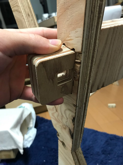
and then, the block is inserted into the hole cut at the support part to fix the leg and support part. the width of the block is the same as the width of the legs.


Done.
Sometimes the milling was succeeded, so I could milled some parts in my final object this week. But I’m planning to use this week’s final object at my final project(Link), so I’ll continue to make the rest parts and complete to assemble them.

Cool~♪
2020/7/21 Postscript
I finally finish making a table for my final project. It includes the assembly part which I described above. It ended up to be a beautiful and functional design.

3. Conclusions
Submission
Self-reviews
1. This week’s work
This week, Hiroaki Kimura who is one of the students in FabAcademy 2020 gave me wood materials and the knowledge about how to deal with wood materials. Yosuke Tsuchiya who is the instructor taught us how to use CNC router. And Hiroyuki Muramatsu who is the graduate in Fab Academy 2017 and now responsible for Fablab Nagano and supports a lot of our works. Everyone is very supportive and helpful for me.
Thank you very much!!
- Tips for Debugging
Hiroyuki Muramatsu taught me “When you are trying to debugging, don’t change the multi factors at once. Change just one factor and try to work, or you can’t find out the cause of the problem even if the problem doesn’t become to happen.” That’s very helpful for me to think about what the problem is and how to solve that problem. (Thank you.)