C. Schedules & Progress
Spiral Developments
| Overview | Nozzle & Pump | CoreXY | Programming | Table | |
|---|---|---|---|---|---|
| 1st | Commercial Product | Make it operate when it received GPS data | Make a Table | ||
| 2nd | Make as package | Make an outer packaging | Make the storage space of PCBs | ||
| 3rd | Make it draw artworks | Make it draw artworks when it received GPS data | |||
| 4th | Make parts as possible | Make a pump | Not use Blynk Make code to send GPS data from smartphone |
Design legs by myself |
Progress Memo
Nozzle and Pump system
■ Modeling and 3D-print the pump mechanism (Week04)
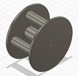
In week04, I modeled the pump system especially the rotation parts.
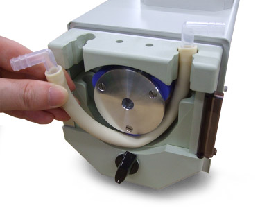
Actually, I wanted the motor pump system like the below image. But that pump takes a lot of pump, so I planed to make the pump system by myself.
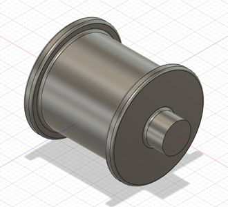
I firstly design the rotation parts.
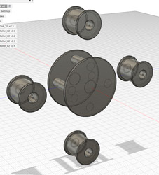
But I noticed that the shaft part is easy to break and thought that I can design it more simply.
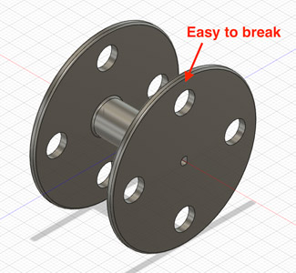
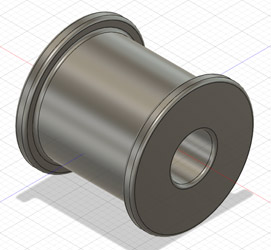
So I re-designed those parts.
And Jointed parts
I printed the pump system.
Cool〜♪
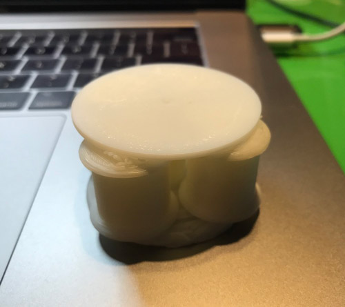
But… Not rotated.
The reason why the rotor cannot rotate is that there was not much clearance between rotors and the plates.
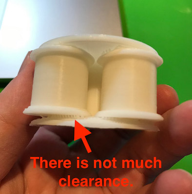
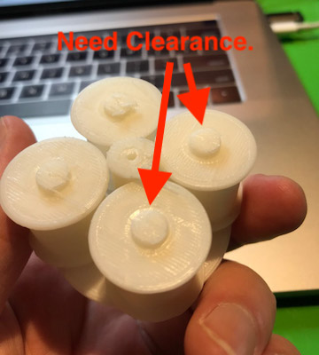
Haru Oguri who is one of the Fab Academy students in Kamakura told me the suitable clearance because he already confirmed the clearance in his week4’s assignment (Thank you, but I should’ve ask him about that before printing…)
So next time, I want to revise the sizes of a shaft and a rotor because giving the clearance.
■ 2020/6/8 Not make pump by myself
I’ve decided to make pump by myself at 4th spiral due to not enough time to make it and its low priority.
I tried buying 3 DC pump motors. One has the different outlet angle of tube from others. Two is driven at 5V. Three is at 12V.
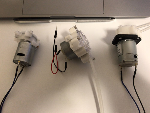
I checked the operation of motor ② by using Arduino IDE and the commercial DC motor driver module.
CoreXY platform
Jun Kawahara who is the instructor in Kamakura gave me the parts of CoreXY system (Thank you). Actually, I just want to learn how to control the CoreXY with programming, so I was planning to buy the parts for CoreXY.
Reference: Circuit board & Programming
Reference: GPS Receiver
Reference: Belt holder
Reference: Core XY 3D data
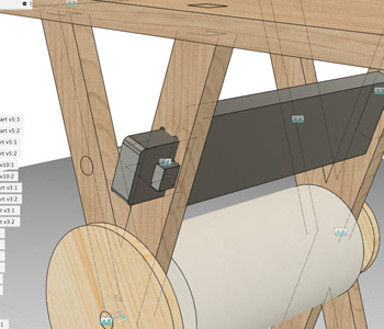
■ 2020/6/8 Designed the overview of CoreXY
As Rico(Phanuwit Rico Kanthatham) who is our instructor in Kamakura advised me that you should make a design of CoreXY so that you can grasp the overview of your final project visually.
So I made it!
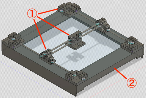
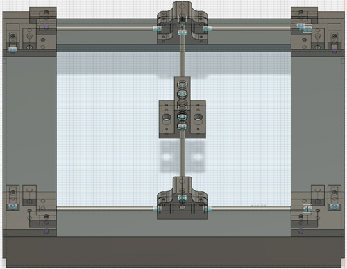
① Support parts: Make by 3D printing
② Outframe: Make by laser cutting of MDF
Programming
At this chapter, I logged two things. One is code: the code to operate the machine. Two is application: the application of sending GPS data.
Code
■ Decided the base code to operate CoreXY
I plan to make CoreXY draw artworks based on GPS data sent from the smartphone. So it needs to make the code receiving GPS data and convert them to coordinate data on CoreXY platform, operating CoreXY based on that coordinate data.
So its code would be complex. So I tried to refer the code made at the last year’s machine week session of Fablab Kamakura member first.
Base Code: .ino
Soooo complex^^;
■ Changed the code
I had no time to understand the base code, so I wrote a simple code to control the DC motor pump by clicking keyboard.
As I push “s” on the keyboard, DC motor pump start driving forward and flow the ink. As I push “b”, DC motor pump start driving backward. As I push “c”, DC motor pump stop to drive.
const int DriverA_1 = A0;
const int DriverA_2 = A1;
//const int DriverB_1 = 10;
//const int DriverB_2 = 11;
char key;
char S = 's';
char B = 'b';
char C = 'c';

void setup() {
  pinMode(DriverA_1, OUTPUT);
  pinMode(DriverA_2, OUTPUT);
  //pinMode(DriverB_1, OUTPUT);
  //pinMode(DriverB_2, OUTPUT);
  Serial.begin(9600);
}

void loop() {
  if (Serial.available()) {
    key = Serial.read();
    if(key == S){
      Serial.print("Start!");
      Serial.println("");
      motor(HIGH, LOW, 3000);

    } else if (key == B){
      Serial.print("Back!");
      Serial.println("");
      motor(LOW, HIGH, 3000);

    } else if (key == C){
      Serial.print("Stop!");
      Serial.println("");
      motor(LOW, LOW, 3000);

    }
  }
}

void motor(int a1, int a2, int d){
  digitalWrite(DriverA_1, a1);
  digitalWrite(DriverA_2, a2);
  //digitalWrite(DriverB_1, a1);
  //digitalWrite(DriverB_2, a2);
  delay(d);
}
■ Revised the code
To meet the assignment of Final Project, the sensor must be added into my product. So I tried using light sensor to give a change to its operation.
The code is below;
const int DriverA_1 = 14;
const int DriverA_2 = 15;
const int plus_sensor = 2;
const int sense_sensor = A2;
const int minus_sensor = 4;
//const int DriverB_1 = 10;
//const int DriverB_2 = 11;
char key;
char S = 's';
char B = 'b';
char C = 'c';

int value = 0;
int threshold = 100;

void setup() {
  pinMode(DriverA_1, OUTPUT);
  pinMode(DriverA_2, OUTPUT);
  pinMode(plus_sensor, OUTPUT);
  pinMode(sense_sensor, INPUT);
  pinMode(minus_sensor, OUTPUT);

  digitalWrite(plus_sensor, HIGH);
  digitalWrite(minus_sensor, LOW);
  //pinMode(DriverB_1, OUTPUT);
  //pinMode(DriverB_2, OUTPUT);
  Serial.begin(9600);
}

void loop() {
  if (Serial.available()) {
    key = Serial.read();
    if(key == S){
      Serial.print("Start!");
      Serial.println("");
      while (Serial.read()) {
        value = analogRead(sense_sensor);
        Serial.println(value);
        if (value < threshold){
          motor(HIGH, LOW, 150);
        } else {
          motor(HIGH, LOW, 10);
        }
      }
    } else if (key == B){
      Serial.print("Back!");
      Serial.println("");
      motor(LOW, HIGH, 3000);

    } else if (key == C){
      Serial.print("Stop!");
      Serial.println("");
      motor(LOW, LOW, 3000);

    }
  }
}

void motor(int a1, int a2, int d){
  digitalWrite(DriverA_1, a1);
  digitalWrite(DriverA_2, a2);
  delay(d);
  digitalWrite(DriverA_1, a2);
  digitalWrite(DriverA_2, a2);
  delay(d);
}
When the value given from the sensor is higher than the threshold value (= 100 in above code), the motor pump drives quickly whereas it is lower than the threshold value, the pump drives intermittently.
So the speed of the motor could be changed with the value from the sensor.
Click the below link to the video!
Video1 - Drive a motor without Ink
I also tried drive the motor with blue ink.
Video2 - Drive a motor with Ink
Table
■ Model a table (Week02)
I designed the overview of a table. but it is a completely copy of Reference model of desk: Ref.1, Ref.2 made by Kirsten Camara.
I firstly modeled almost the same design with Ref.
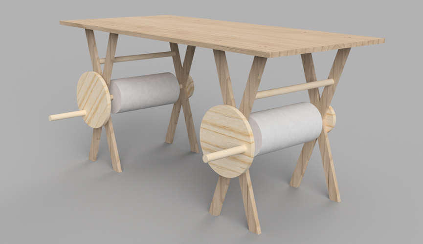
The components are below;
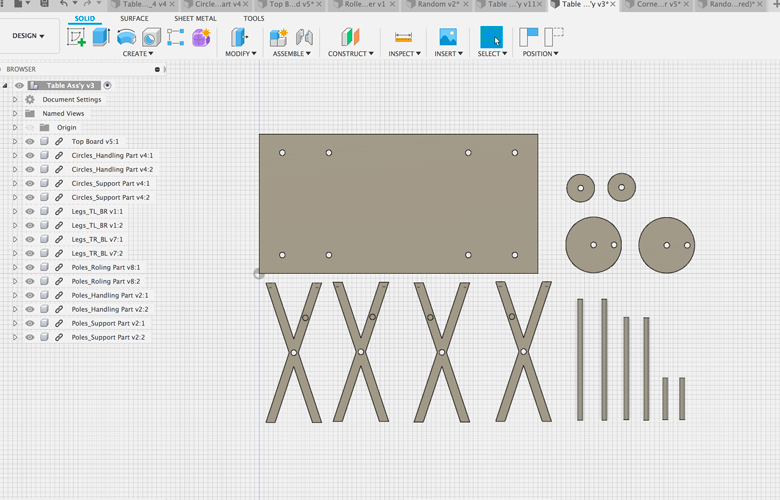
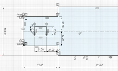
■ Re-design a table (Week07)
In week02, I added some revisions:
- Decide the actual sizes of the table.
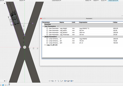
- Designed with Parametric Design.
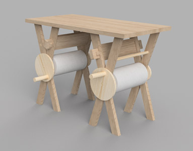
- Reinforced the table with some support parts.
Parametric Design
Added the support parts as below;
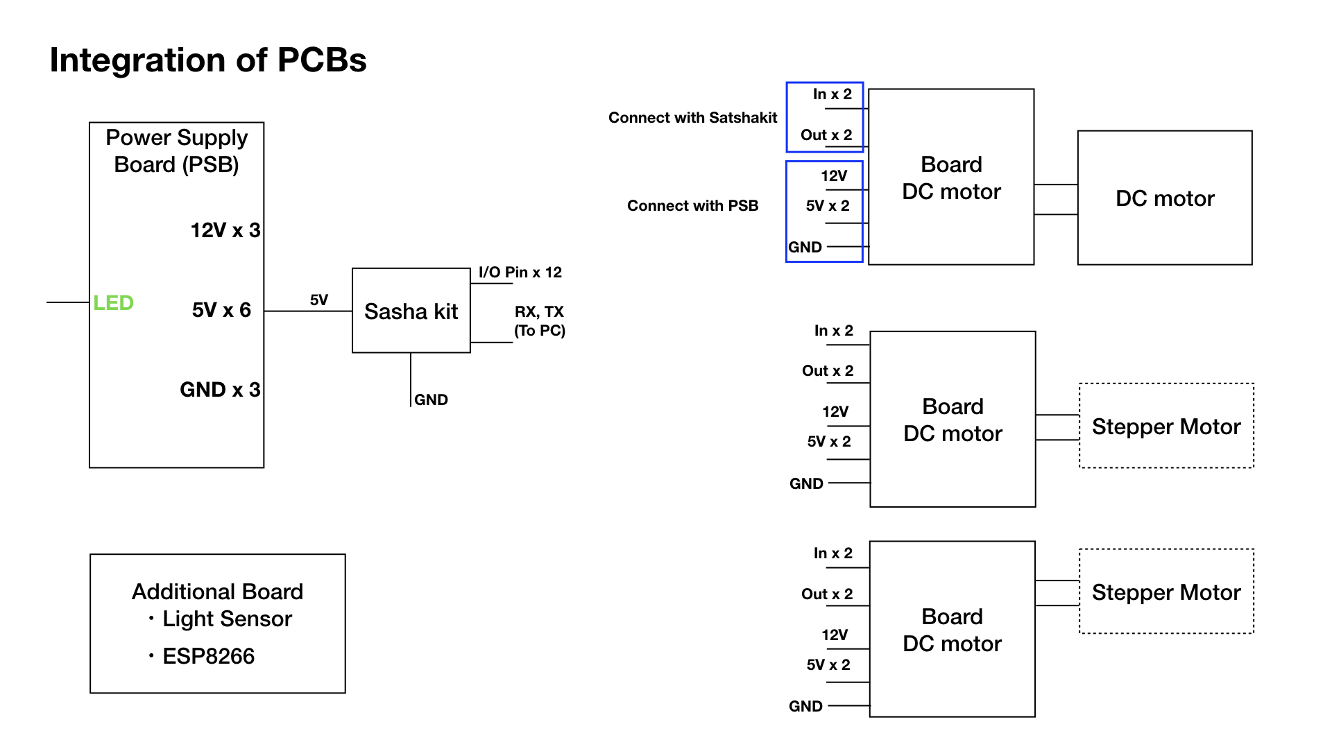
Circuit Integration
■ Drew the overview of the integration of PCBs (Week10)
At the local session of week10, I organized and drew the overview of the integration of PCBs.
Integrated PCBs on the drawer…
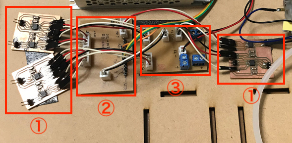
① Motor Driver Module x 3
② Power Supply Module
③ Main Computing Board
*Milling pass data are attached in the “What did you design”: table in A. Final Project page.
Logo Sticker
■ Made a Sticker (Week03)
I discussed to make a logo for my final project in week3 with Kae Nagano who is my instructor.
So I designed the logo using Illustrator and make a logo sticker using a vinyl cutter.
Please watch the detail about how to make a sticker from my week3 page.
Here is the logo sticker I designed.

And finished!!