Final Project
Auto Foot Washer ( Still...... Finding a Better Name for this project)

The Inspiration for this project came from my father’s scolding.
Due too, some sudden what’s app advise...... example - “washing feet”...... my father started follow and gave some drill/execise based on washing the foot everytime before entering my house.
During this practise… He often yell my name.... The reasons for his yelling are:-
-
Not Washing properly....
-
Wasting more water.....
-
Walking with wet feet......
-
taking more time to wash…
Realtime work of the Foot Washer.....
-
Foot is detected by UltraSonic sensor....
-
After detection, when a button is pressed. From the Water pipe the water is hits the leg for “20 sec”(for an example)..
-
After a water wash… If the person, want to clean his leg, there will be a rotating bursh 15cm above from the filter… so the person can clean his foot by varying the speed of the potentiometer.
-
If the person want to wash his leg once again, he can, by pressing (water wash) button. Or If the person want to go… He can dry his feet before, he go inside his house with wet feet… For this there is a push button which turn’s “ON” A DC FAN for drying his feet.......
To make this process easier...... I need a machine… to solve these problems......
At present, my thoughts is...... making this project..
So, this is the title card....

For that, I introduce a machine called foot-washer.....
Hand Sketch of Auto-Foot Wash.
This is the Hand sketch..... of my project..........


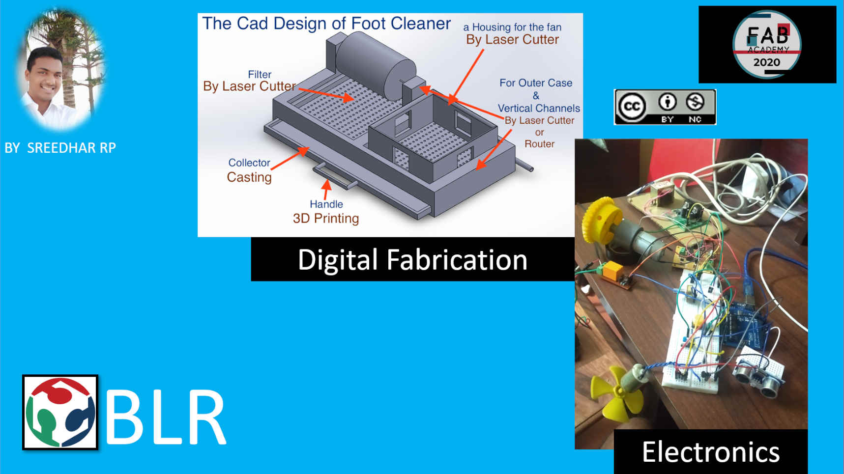
Later, with proper thinking, I changed some of my hand-drawing design..... with 3D-Cad design.


The Electronics Design ........

What materials and components will be used?
The Materials and Components used in this projects
* Electronic Component
* OUTPUT Devices
-
DC Gear Motor (12V)
-
DC PC fan (5V)
-
Motor Driver
-
Water Pump
-
Ac to Dc Power Supplier of 12V
* INPUT Devices
-
Ultra Sonic Sensor
-
Potentiometer
-
Button switch
-
Push button switch
-
Relay Board
* Mechanical Components
-
Axle
-
Pipe
* Other Components
-
Round Bursh
-
For the filter, (Acrylic sheet)
So, Far these are the material, I need to buy is round bursh, Pipe......
The Work-Process
-
Pencil Sketching of the Symatic
-
For Designing the Outter Case, Housing(DC fan), water filter, water collecting tray, etc
-
SolidWorks
-
For Designing the PCB’s
- Ki-cad
-
Then the electronics production, which consist of :
- Milling
-
Soldering
-
Constructing/Assembling (for this I will take help from the machine, Like Laser cutter, Router, 3D printer , vinyl cutter).
-
For Programing (Trying in different programing languages)
- Arduino
- C (Try)
- Python (Try)
-
Assembly (Try)
-
Trial run
-
Debugging for any issuse…
-
Completion of Project…
-
-
-
Hence, This the Workflow.
The Cost of the Project..
Will be updated soon......
What parts and systems will be made?
As, I mentioned, as per my visualization,
-
I need to make a outter case..
-
Water filter
-
Water collector
-
A support for the Brush to rotate.
-
Housing for the fan…
-
Microcontroller....
The Electronics Work-flow
The Slide Of my final project
The Video Clips of my final project
Very soon it will be edited.................hello
For a change, I thought of making the foot wasking bursh…
This is digital design…(Intermixing of CAD designs)

This is round housing, which holds bursh…

But still, I have change of thought to change the mechanical design....
During saturday’s meeting, I got many ideas… in approch my final project…
This is the new design, from the box shape design…

still, I should make better design… in CAD software.. Before making it as a real modal..
Moreover, after learning about making PCB and design PCB, I have design my own “Arduino” know as MASKduino. I did it, with kicad software.
This is “MASKduino”

The board size is -> Length = 78.232mm -> Width = 84.074mm
Now, I am also working with wireless trasmission with IR remote.
CODE
int echo = 3;
int trig = 2;
int mot  = 9;
int button = 5;
int butnew;
int aot = 10;
int pot = A0;
int potvalue;
int but = 7;
int dcmot = 11;
int butvalue;

int rotspeed;


float distance;
float pulseTime;


void setup() {

  Serial.begin(9600);
  pinMode(echo,INPUT);
  pinMode(trig,OUTPUT);
  pinMode(mot,OUTPUT);
  pinMode(button,INPUT);
  pinMode(aot,OUTPUT);
  pinMode(pot,INPUT);
  pinMode(but,INPUT);
  pinMode(dcmot,OUTPUT);


}

void loop() {

  digitalWrite(trig,LOW);
  delayMicroseconds(1000);
  digitalWrite(trig,HIGH);
  delayMicroseconds(20);
  digitalWrite(trig,LOW);

  pulseTime = pulseIn(echo,HIGH);
  pulseTime = pulseTime/1000;

  distance = pulseTime * 347.22;

  distance = distance / 2;

  butnew = digitalRead(button);
  potvalue = analogRead(pot);
  rotspeed = 0.249 * potvalue;

   butvalue = digitalRead(but);


  if(distance<=150){

    Serial.println("HELLO");

    if(butnew==0){
      digitalWrite(mot,HIGH);
      Serial.println("It is working");
      delay(10000);
      digitalWrite(mot,LOW);
    }
    }
    else{

    digitalWrite(mot,LOW);
    Serial.println("It is not working");
 }

   Serial.println(rotspeed);
   analogWrite(aot,rotspeed);

     if(butvalue==0){
    analogWrite(dcmot,100);
  }
  if(butvalue==1){
    analogWrite(dcmot,0);
    }

}