Embedded programming
In week 5 we had our first introduction into electronics. We milled, soldered and prepared a ISP (In-Swystem-Programmer that is used to program AVR microcontroller). In week 7 we designed, milled, soldered and prepared our first AVR microcontroller. Week 9 is the week where we bring them together and actually start bringing them to use. In the past I played around with microcontrollers at a basic level so I have a good understanding of what they can do and what they can be used for. Since the board we are using this week was completely made by me I was quite nervous about how it would work. Expecting a marginally more complex process than I was used to.
We started this week with getting to know other microcontroller architectures, reading datasheets for parts and chips and programming our boards.
Tools used this week
Hardware
ISP (week 5)
Hello Echo board (week 7)
USB cable
CP20OX connector + jumper wires
Software
Arduino IDE
USB to UART driver
ATTINY drivers
Documents
ATtiny44A Datasheet
Button Datasheet
Microcontrollers
For the group assignment we looked at different microcontroller architectures. We analysed a selection with a wide range of complexity. Micky and Joey looked at the Makey Makey, a super simple microcontroller made for kids and the ESP8266, a fun, cheap, microprossesor that can make any project connected to the internet. Rutger looked at the 555 timer, a ancient IC (fromt the 70's) with very basic but usefull timing capabillities. Heidi and I looked at the Raspberry Pi Zero that is a crossbreed between the ESP8266 and a computer.
| Board | Raspberry Pi zero |
|---|---|
| Link to datasheet | |
| Performance & Technical specifications | |
| Voltage | 5.1 V with 1-2 amp |
| Chip architecture | BCM2835 SoC |
| (clock)speed | 1GHz |
| Memory | 512MB RAM,and uSD slot to run OS from micro sd |
| Pins (type and amount) | 26 GPIO pins, 2 Control pins, 5.1 and 3.3 v vcc and |
| other special features | Video mini HDMI PAL or NTSC via pads HDMI capable of 1080p USB microB for power microB for OTG Audio from HDMI port only |
| Workflow | |
| Connecting to the device | Flash software onto the SD and put it in the Raspberry. |
| Programming environment | Compatible Raspberry Pi IDE or directly on the Pi itself |
| Programming language | Recommended is Python but other options are possibleCompatible Raspberry Pi IDE or directly on the Pi itself |
| Coding the device | Micro SD card or directly attaching a keyboard and display. |
You can find more about the other microcontrollers here:
MakeyMakey & ESP8266 - Micky | Joey
555 timer - Rutger
Raspberry pi Zero - Heidi
Reading datasheets
Every part we use on our boards comes with a datasheet. Datasheets are made by the manufacturer to answer (in extreme detail) any question you might have. Although the parts we use are really small there can be a lot to them. For example the a 1k resistor comes with a detailed 10 page (!) datasheet.

The more complex the part is, the datasheet will be aswell. The IC (ATTINY44A) we used for our microcontroller looks like a simple black 14-legged creature. And it comes with a 229 page datasheet. Reading and undstanding everything is a bit to far fetched for me. The best strategy for these datasheets is to go to them if you have specific questions you need answered. I made a list of (my) 7 questions I wanted to answer (in no particular order).
Q1: What are the pins?
Q2: What can the pins be used for?
Q3: How much memory does the ATTINY44A have?
Q4: Why does my board have an external resonator?
Q5: What are the dimensions of the ATTINY44A
Q6: Is it possible to use PWM?
Q7: How much power does my IC need.
Q1: What are the pins?
When we designed our board in week 7 we had to connect the IC to the other parts on our board. For example for powering and programming there are a requirements. For power we need to connect the IC to VCC and GND. In the snapshot below (taken fromt he datasheet) you can see these are located at 1 and 14 (also note the orientation). For programming we additionally need MISO, MOSI, SCK and RST. Just below the schematic all ports get further explanation. The numbers on the chip tell us how they are numbered - these are using when making schematics. Than there are the names (VCC, GND, PB0-PB03 and PA0-PA7), these are a bit more descriptive. VCC and GND are for power and PA and PB have alternate functions that are described between parentheses. On my board the resonator is connected to two PB ports and the LED and button to PA ports. To communicate with these ports in our development enviroment leg number 10 will be referred to as 3.
Q2: What can the pins be used for?
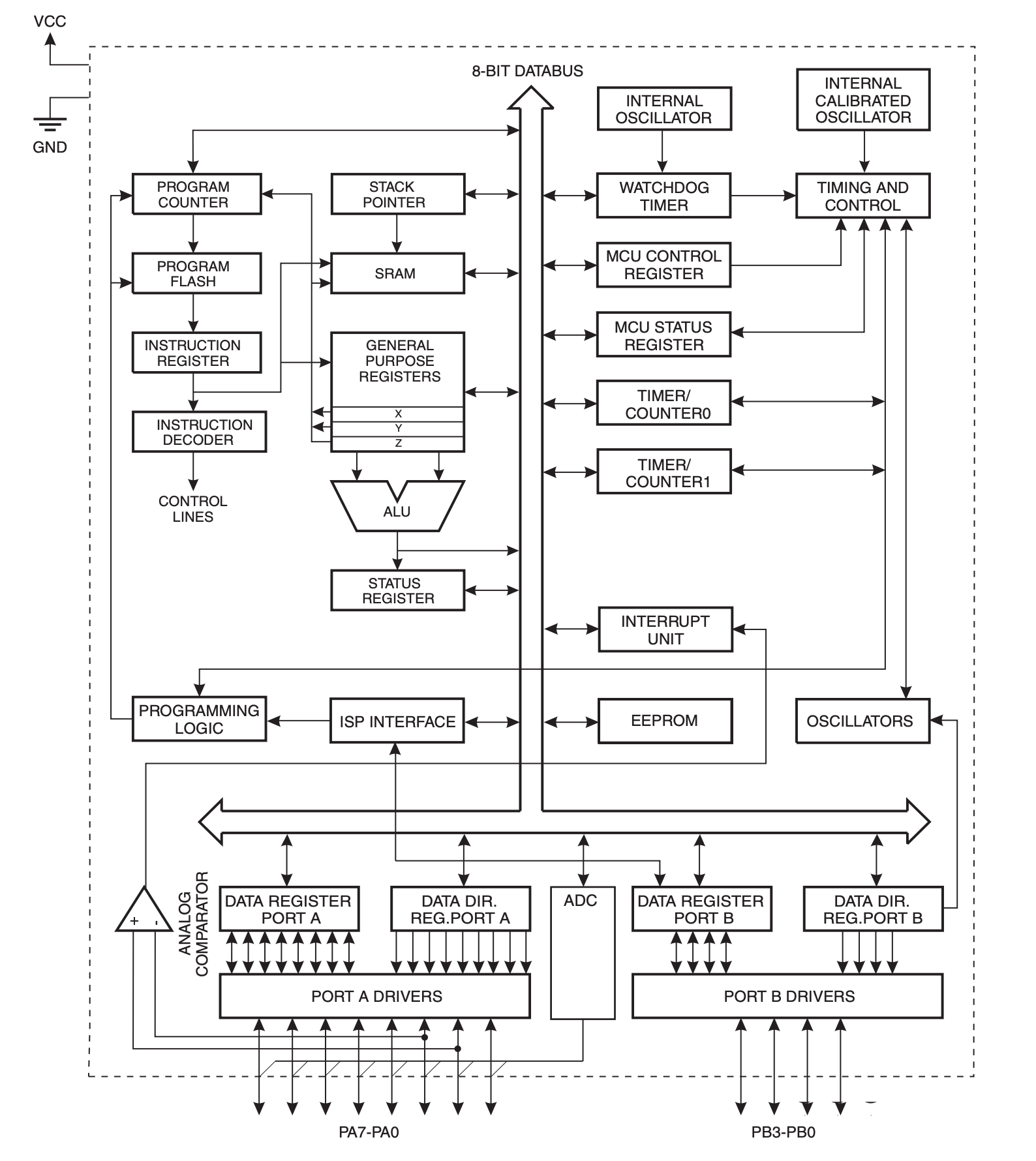
My original thought when trying to programm the IC was that I could only use unused legs for extra parts. In reality this is partly true. During programming we do need to connect to specific legs to communicate but once this is done these can be used for different purposes. All port AD drivers are connected to the ADC (analogue to digital converter) as seen in the block diagram. These pins can read and wrote volts (0v to 5v). Each block in the schematic represents a different subsystem of the chip and is also explained in the datasheet.
Q3: How much memory does the ATTINY44A have?
In the fifth chapter memories are explained. My actual question is, how large can my programm be? The ATTINY has three different memories: In-System Re-programmable Flash Program Memory, SRAM Data Memory and EEPROM Data Memory. The In-System Re-programmable Flash Program Memory contains 4K byte flash memory for program storage. The SRAM DATA Memory has 32 general purpose working registers, 64 I/O registers and the 128/256 bytes of internal data SRAM. The ATTINY has 128/256 bytes of data EEPROM memory, this is nonvolatile (it's not lost when the device is switched off ). It is organized as a separate data space, in which single bytes can be read and written. Fun fact, the EEPROM has an endurance of at least 100,000 write/erase cycles. This makes absolutely no sense to me but I found the following video that explains it. If I understand correctly the space available for my programming is 4k bytes (4000 bytes) - each byte holds a 32 bit instruction. I am quite intrested in figuring out how these memories can be used in praxis.
Q4: Why does my board have an external resonator?
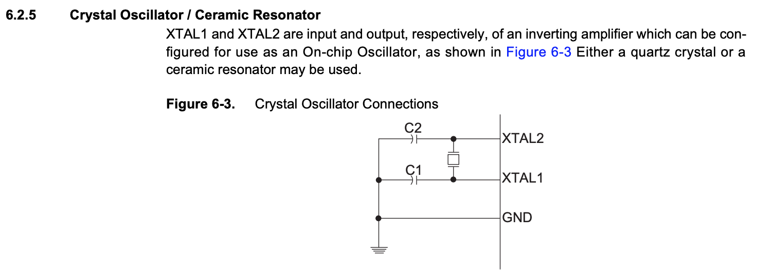
During my electronics design week we touched this subject briefly. On the board we made is a IC, the chips has a internal oscillator that takes care of the timing. We also connected an externial resonator (also to manage the timing). The timing done by the internal resonator is relatively slow so it's recommended to use a external one. In the datasheet it says the internal is 128 kHz. It also shows us how to connect the external resonator.

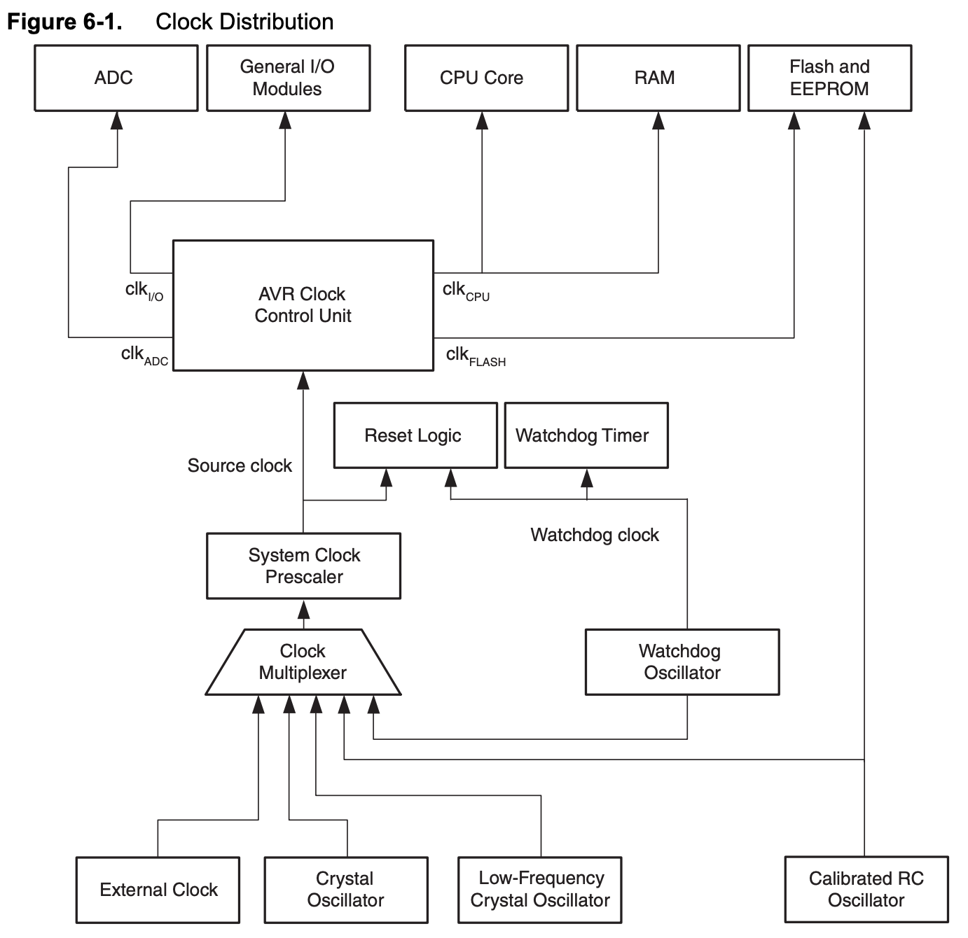
And in the clock distribution diagram we can see how the external resonator connects to to the subsystems via the clock multiplexer. The resonator on our microcontroller is 20gHz (=20.000kHz). This makes a 150x difference between the external and internal clock.
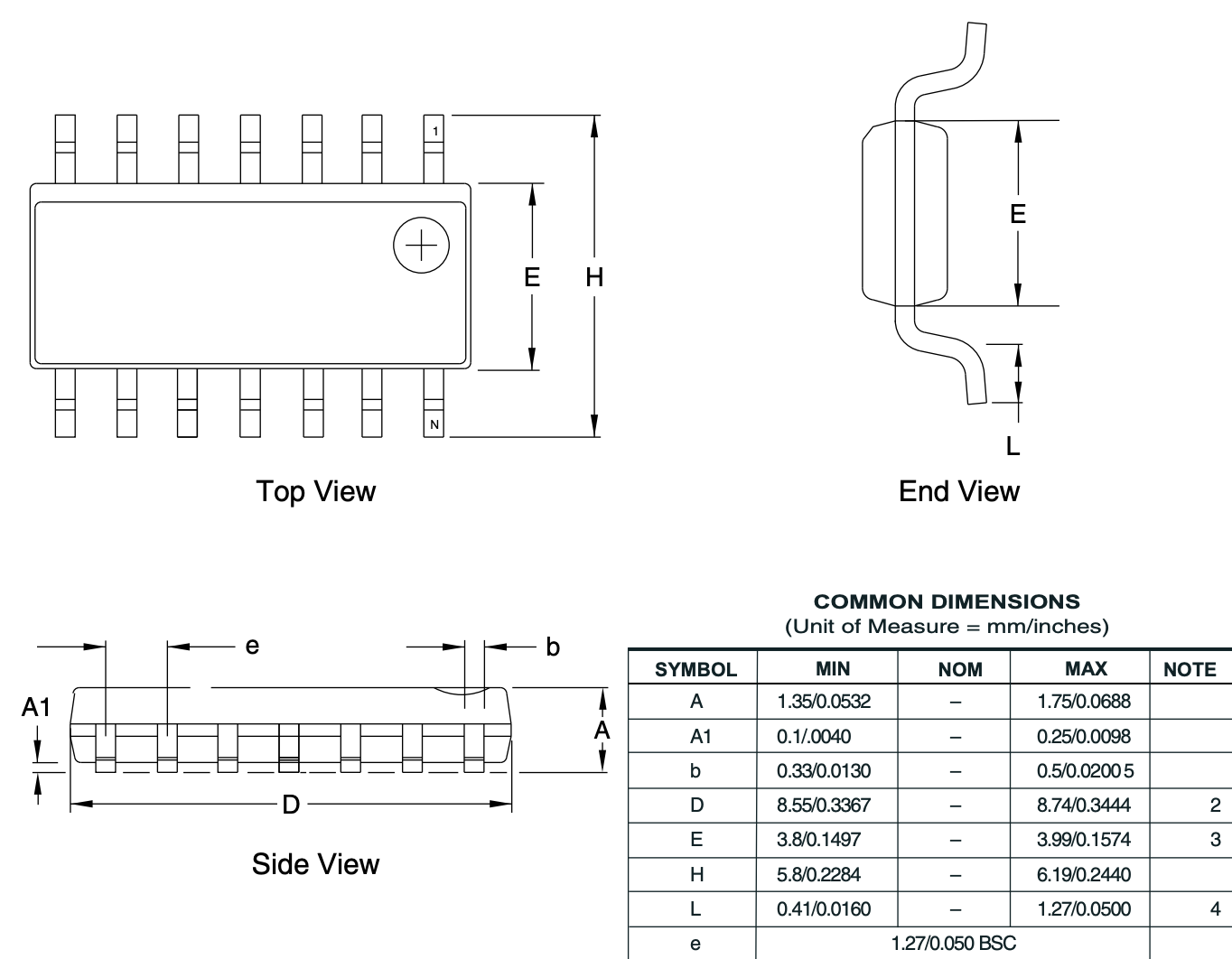
Q5: What are the dimensions of the ATTINY44A
When we were designing and milling the PCB we already had a footprint library taking care of this part. I remember watching a tutorial on how to add your own footprints. To do this you can try and measure the part but that can be quite a task with parts being this small. The datasheet shows all dimensions of the ATTINY44. The black plastic part is 3.8mm x 8.55mm x 1.34mm (w x l x h).
Q6: Is it possible to use PWM?
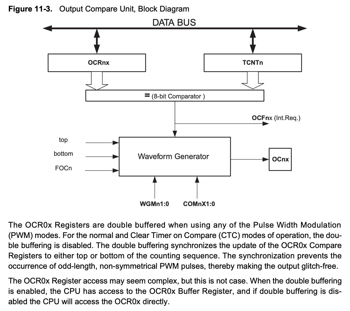
For my final project I want to fade a light. For this I need pulse width modulation ports. The ATTINY has four OCR0x ports that are double buffered when using any of the Pulse Width Modulation. PWM can be used on legs 5 to 8.
Q7: How much power does my IC need.
In my search for an answer I found a interesting diagram. It shows that when the clock frequency is higher it needs more power. A higher speed equals more calculations equals a need for more power. Since I am using a external resonator of 20kHz I need between 4.5V and 5V.
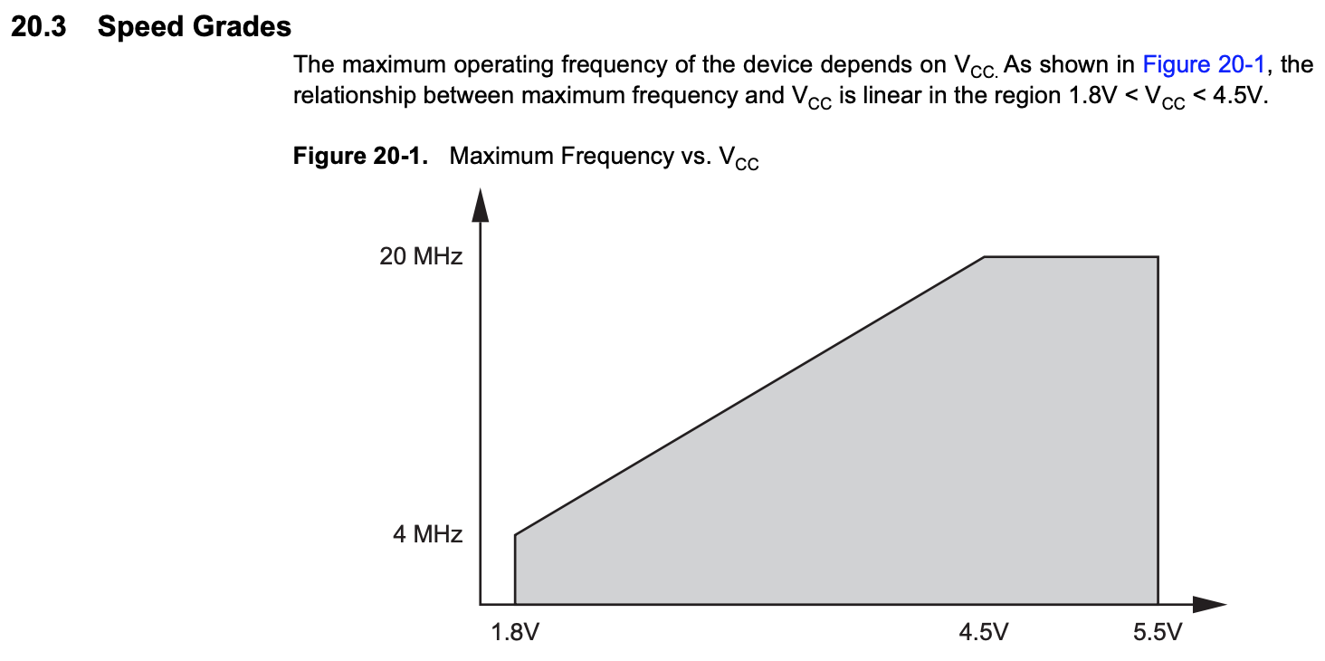
In the maximum ratings diagram you can see the maximum operating voltage is 6V.

Getting started
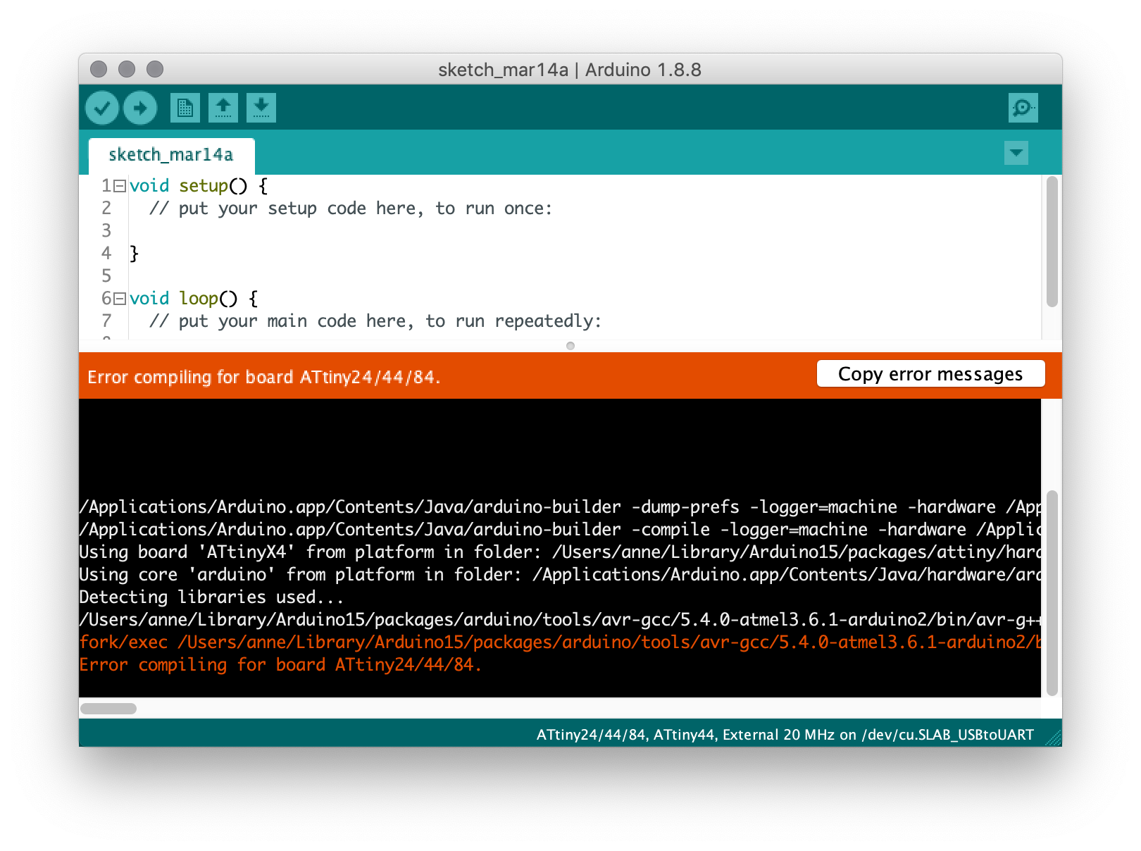
This week I struggled a lot getting my first program onto the ATTINY44. I am using a Macbook Pro with the latest install of Mojave. Ten years ago Apple decided to transition to 64-bits hardware and software. This is bad news for 32-bits apps like Arduino IDE, after Mojave they will no longer be supported. Trying to open 32-bits apps in Mojave still works but already give some unexpected compatabillity issues. In the past the Arduino IDE has always worked fine. Opening the IDE and trying to upload a sketch gave me the following warning.
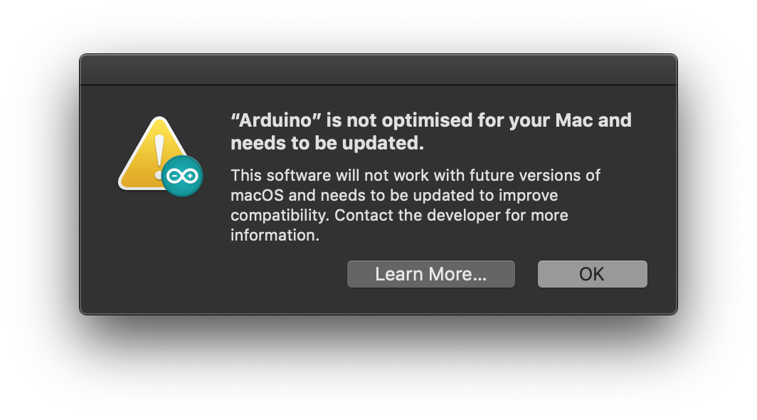
The warning was followed with a compiling issue. In the orange lines you can see that there is an issue with the AVR-GCC library. I looked for the folder and it did excist but was completely empty. I removed Arduino IDE and reinstalled it to see if it would fix this folder. This didn't work so I tried it with a older version, also no luck. Than I tried older versions of my other libraries, reinstalling libraries, checking all settings, restarting my computer, a different IDE (Atom), reinstalling USBtoUART, sweet talking and nothing worked.
Than Heidi pointed out to me that she had a related issue in week 5. Crosspack hadn't installed properly on her system so she had to do some additional steps. She recommended me to install AVR-GCC via the command line.
MBP~$ brew doctor
MBP~$ brew update
MBP~$ brew cleanup --prune-prefix             // necesarry steps to get homebrew up to date
MBP~$ brew tap osx-cross/avr
MBP~$ brew install avr-gcc                    // this took about 20 min.
I tried again and still I was pleasantly surprised with a second error: can't find vrdude: Error: Could not find USBtiny device (0x1781/0xc9f). I reinstalled AVRdude since vrdude wasn't found.
MBP~$ brew install avrdudeWhen this was finished I looked for my device in the command line and received another error. This is where my instructor came to the rescue and checked my device. He told me to flash a make file, here we used the wrong file and bricked the IC, so it had to be replaced.
MBP~$ avrdude -c usbtiny -p t44

avrdude: AVR device initialized and ready to accept instructions

Reading | ################################################## | 100% 0.00s

avrdude: Device signature = 0x1e9207 (probably t44)

avrdude: 5 retries during SPI command
avrdude: 1 retries during SPI command
avrdude: 2 retries during SPI command
avrdude: safemode: Fuses OK (E:FF, H:DF, L:FE)

avrdude done.  Thank you.
Once I replaced my IC I was able to burn the bootloader and start programming.
MBP~$ avrdude -c usbtiny -p t44

avrdude: AVR device initialized and ready to accept instructions

Reading | ################################################## | 100% 0.00s

avrdude: Device signature = 0x1e9207 (probably t44)

avrdude: safemode: Fuses OK (E:FF, H:DF, L:5E)

avrdude done.  Thank you.
Programming
To programm a microcontroller a plethora of languages can be used. Ultimately the IC wants to receive a HEX file. HEX files are readable for chips but not so much for the human eye. Languages like C, Arduino and Python are better options for humans. These languages can be translated to HEX files. This week I am using Arduino language to programm my microcontroller and use the Arduino IDE to translate and send it to my microcontroller.
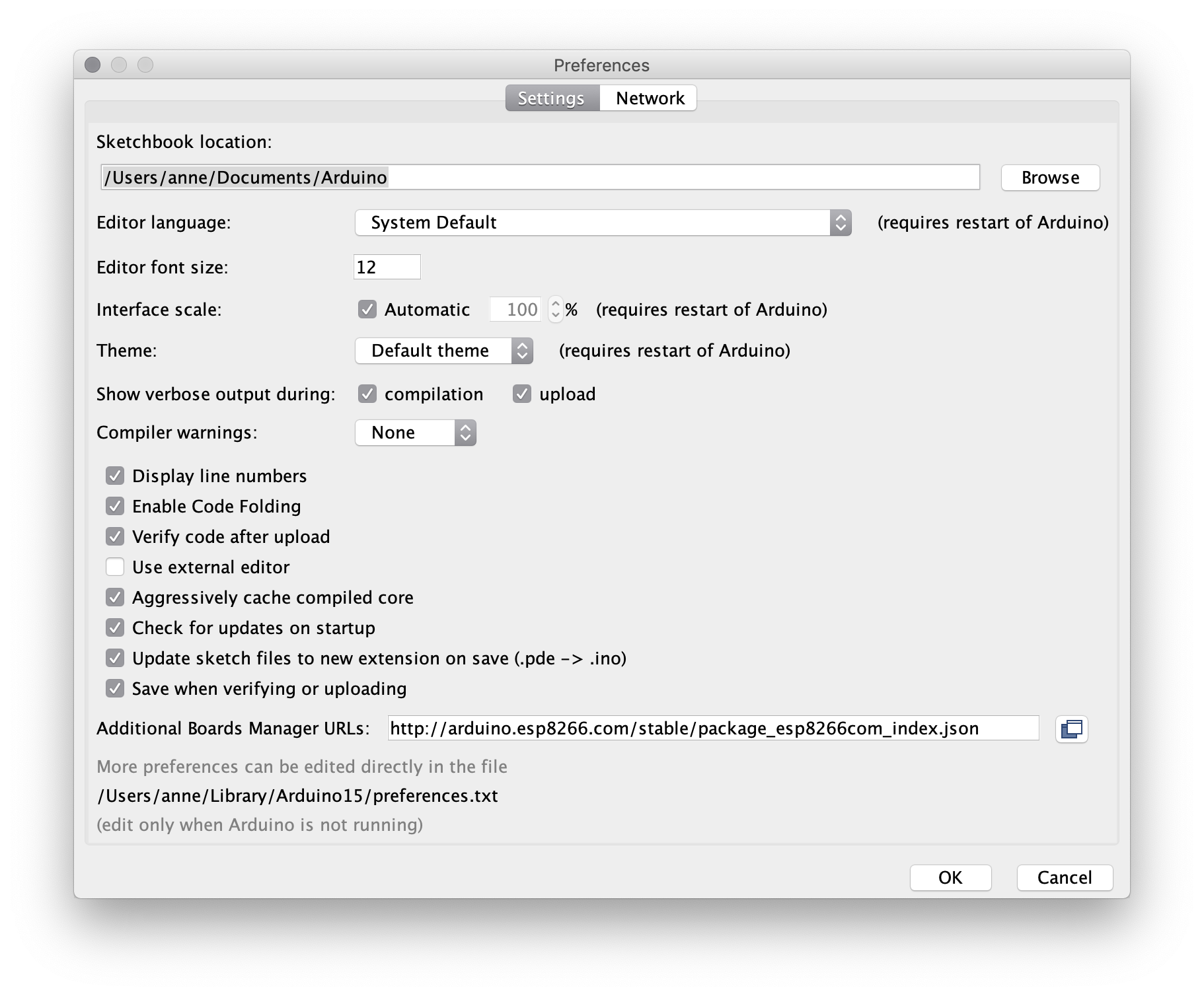
If it's your first time doing this you need to take some extra steps to get Arduino IDE ready to connect to your board. First step is to download and install the USB to UART driver. Next add the ATTINY to the boardmanager in Arduino IDE in File > Prefrences.
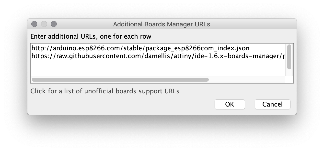
In Tools > Boardmanager search for AVR and install the latest version.
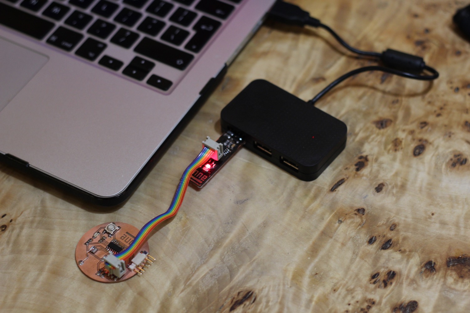
Change all settings in the tools menu to the following. Now connect your microcontroller to your ISP and connect the ISP to the computer and burn the bootloader. The bootloader is the operating system of the chip, this part of the process only needs to be done once. From now on the microcontroller is directly programmable using Arduino IDE.
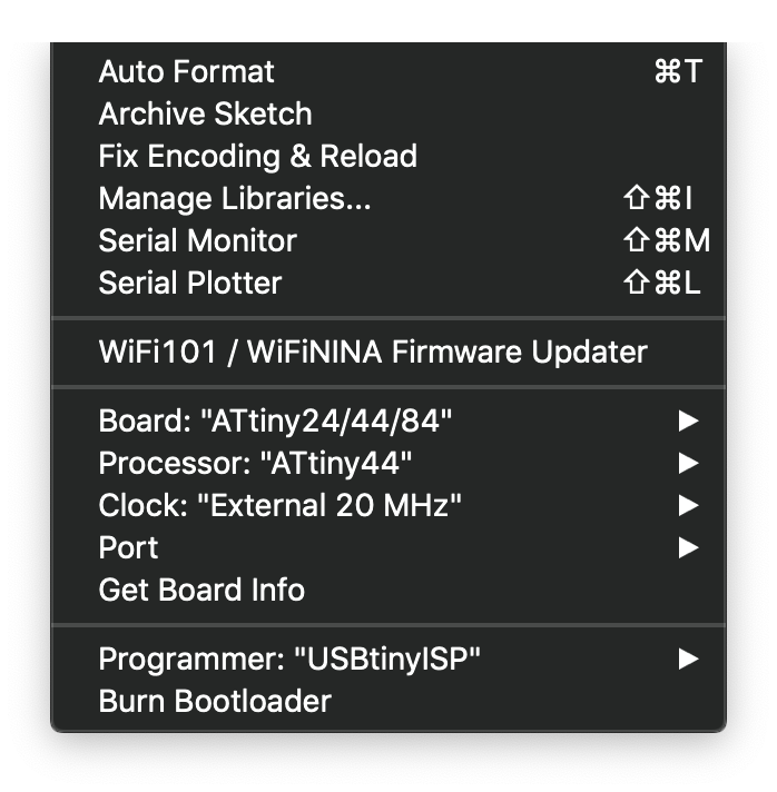
Now it's time to write the first programm to test the board.
// Blink sketch

void setup() {
  // initialize digital pin 6 as an output.
  pinMode(7, OUTPUT);
}

void loop() {
  digitalWrite(7, HIGH);   // turn the LED on
  delay(500);                       // wait x milliseconds
  digitalWrite(7, LOW);    // turn the LED off
  delay(500);                       // wait x milliseconds
}
To upload a sketch simply click verify and upload in the top bar. The LED should now start to blink. Every time a new code get's send to the Arduino it briefly resets the memory to allow reprogramming. This takes a couple of seconds.
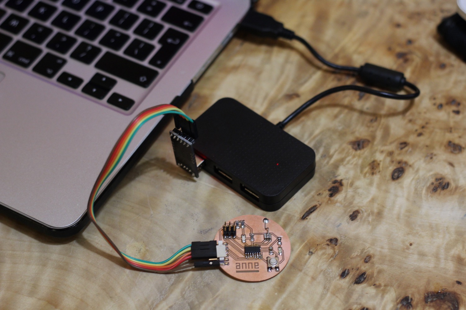
To use the serial communication a few additional steps are needed. Use the ISP to program - with the additional code from below. After the programming disconnect the ISP and connect the CP20OX connector to the board.
// Serial communication start sketch

#include <SoftwareSerial.h>         // import serial library
#define rxPin 0                     // link  rx and tx pins to library
#define txPin 1

SoftwareSerial serial(rxPin, txPin);

void setup (){
  // your code
  pinMode(rxPin, INPUT);
  pinMode(txPin, OUTPUT);
  serial.begin(9600);               // start serial communication
}

void loop (){
  // your code
}
Hello Henk Sketch
The code I wrote for this week does a couple of different things. The first thing I programmed was for the sensor to change the brightness of the LED. The second thing I wanted it to do was for a port to power a hot wire for a couple of seconds and than stop again.
Timing
The standard way to do timing is by using millis, this doesn't require any special library. I did use a special library, elapsedMillis.h to help me keep track of time. With elapsedMillis it's possible to reset the timer back to zero and create multiple timers that can be controlled independantly. Ofcourse you can do this without a library but for me this method makes it a lot more readable. Especially once code becomes more complex.
In the code I wrote what each part does. Once the programm is uploaded the hotwire can be connected to pin 6 (MOSI) and GND. The board can be connected with the CP20OX for serial communication. The serial communication can be viewed in Tools > Serial monitor.
* The following sketch is made by Anne Vlaanderen | march 18 - 2019
 *
 *  This sketch does two things.
 *
 *  1. a light fades in and out using the light sensor
 *     when the board gets power the sensor get's calibrated
 *  2. when a button is pressed a smoke test of x seconds is performed
 *     a heat wire is connected to GND and MISO to do this
 *     heat wire is wrapped around some cotton with glycerine and fragrance oil
 *     heat wire should have a resistance at this point between 3 and 5 ohms
 *
 *    values can be read in the monitor if the board is connected with a usb connector
 *
 */

 // library used for easy timing
 #include <elapsedMillis.h>
elapsedMillis timeElapsed;

// library used for serial communication
#include <SoftwareSerial.h>
#define rxPin 0
#define txPin 1

SoftwareSerial serial(rxPin, txPin);

// variables for ports and values
int buttonPin       = 3;
int buttonValue     = 0;

int sensorPin       = 2;
int sensorValue     = 0;
int sensorLow       = 1023; // needed for callibration
int sensorHigh      = 0;    // needed for callibration

int ledPin          = 7;

int smokePin        = 6;
int smokeValue      = 0;

void setup() {
  // serial communication
  pinMode(rxPin, INPUT);
  pinMode(txPin, OUTPUT);

  // button
  pinMode(buttonPin, INPUT_PULLUP);

  // sensor
  pinMode(sensorPin, INPUT);

  // led
  pinMode(ledPin, OUTPUT);
  digitalWrite(ledPin, HIGH);           // switch light on to indicate callibration

  // smoke
  pinMode(smokePin, OUTPUT);

  // this part of the code calibrates the light sensor during the 5 first seconds
  // new values are stored in sensorLow and sensorHigh
  while (millis() < 5000) {
    sensorValue = analogRead(sensorPin);

    // record the maximum sensor value
    if (sensorValue > sensorHigh) {
      sensorHigh = sensorValue;
    }

    // record the minimum sensor value
    if (sensorValue < sensorLow) {
      sensorLow = sensorValue;
    }
  }

  digitalWrite(ledPin, LOW);            // switch light off to indicate callibration is finished

  // start serial communication
  serial.begin(9600);
}

void loop() {
// code that switches the smokePin for 3 seconds on when button is pressed
buttonValue = digitalRead(buttonPin);

if(buttonValue == LOW){
    digitalWrite(smokePin, HIGH);
    smokeValue = 1;
    timeElapsed = 0;
}

if(timeElapsed > 3000) {
          digitalWrite(smokePin, LOW);
          smokeValue = 0;
}

// sensor values mapped for led
sensorValue = analogRead(sensorPin);
sensorValue = map(sensorValue, sensorLow, sensorHigh, 0, 255);
sensorValue = constrain(sensorValue, 0, 255);
analogWrite(ledPin, sensorValue);


// prints of all data for monitor
 serial.print("time:  ");
 serial.print(timeElapsed/1000);
 serial.print("\t");
 serial.print("sensor:  ");
 serial.print(sensorValue);
 serial.print("\t");
 serial.print("smoke:  ");
 serial.print(smokeValue);
 serial.print("\t");
 serial.print("button:  ");
 serial.println(buttonValue);

  delay(30);
}
Serial monitor
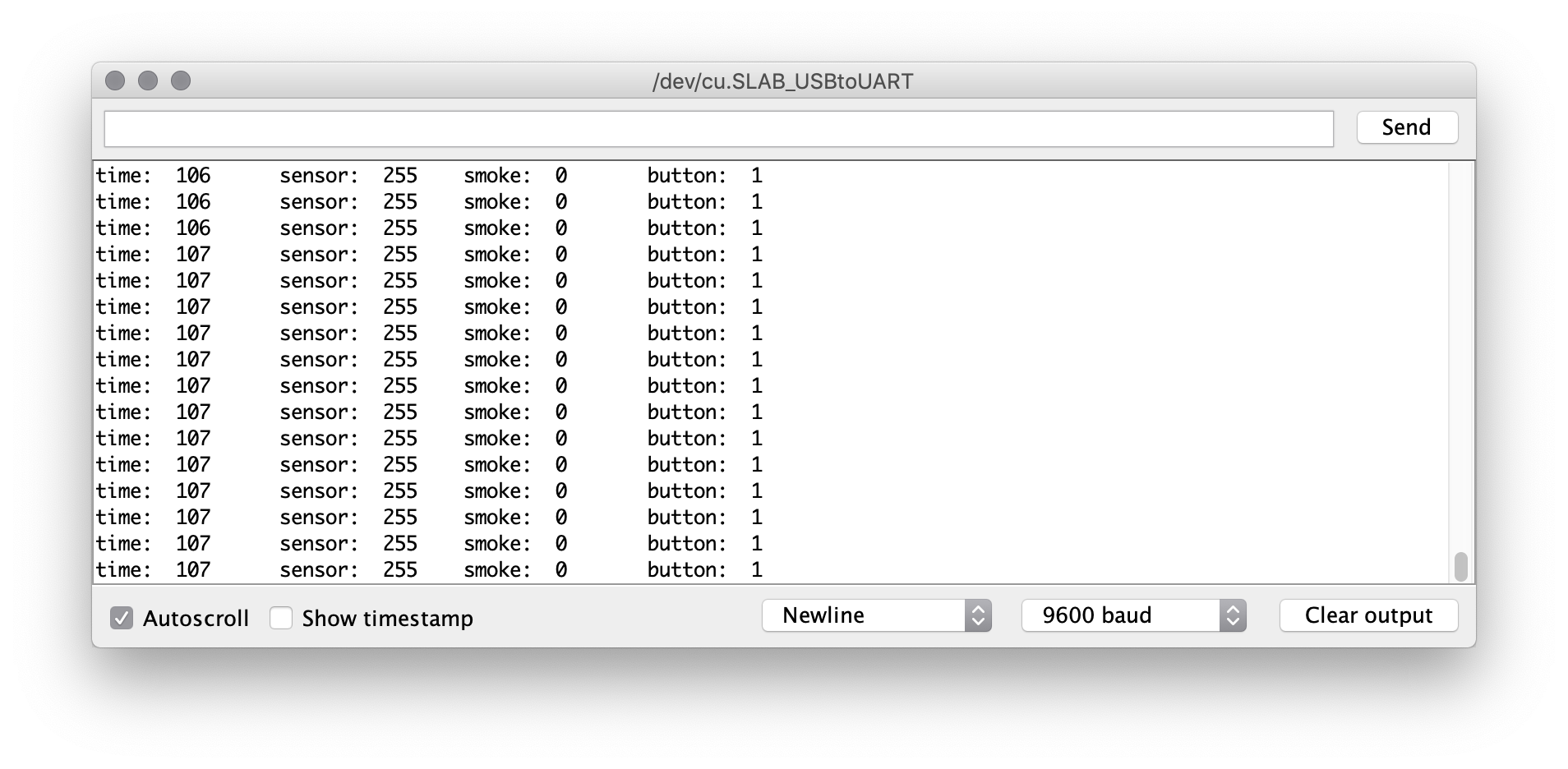
Time = seconds past since last reset.
Sensor = sensor value mapped to a value for led (0 - 255).
Smoke = smoke on or off - ends with a reset of time.
Button = button on or off.
Hook up for programming
Hook up for serial communication (CP20OX)
Programming using Atom & PlatformIO
To try out another enviroment I chose to use Atom. Since I use it for my documentation I already have it installed.
If you still need to install it you can find it here.
To use Atom to program there is another thing that is needed; PlatformIO IDE for Atom. From their website just follow the installation instructions. I will be using my master board from the networking week.
Once everything is up and running you are good to go.
Step by step guide
- Start a new project from PlatformIO.
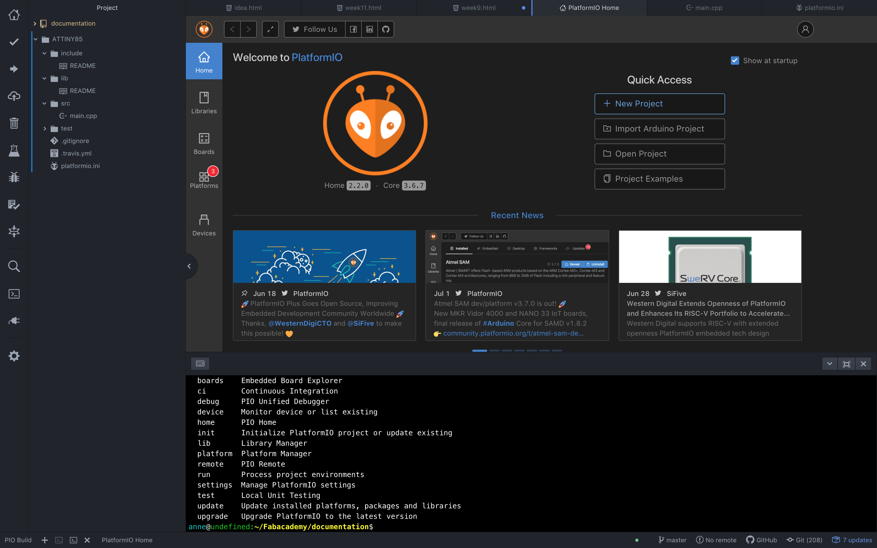
- Give it a descriptive name and select the correct board/chip. Click finish and wait a few seconds for the project to be created.
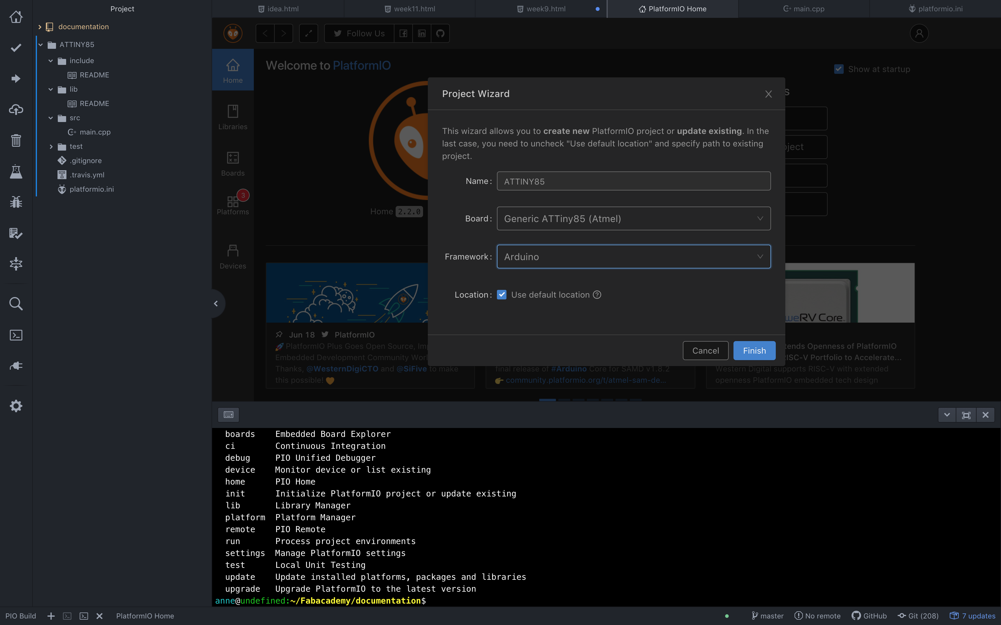
- On the left hand side you can now see your folder with files. For now only two are important. The first one is 'platformio.ini'. This file holds some settings. Here a few lines need to be added.
[env:attiny85]
platform = atmelavr
board = attiny85
framework = arduino
attiny85-8.build.f_cpu=8000000L // this code sets the internal 8mhz clock speed
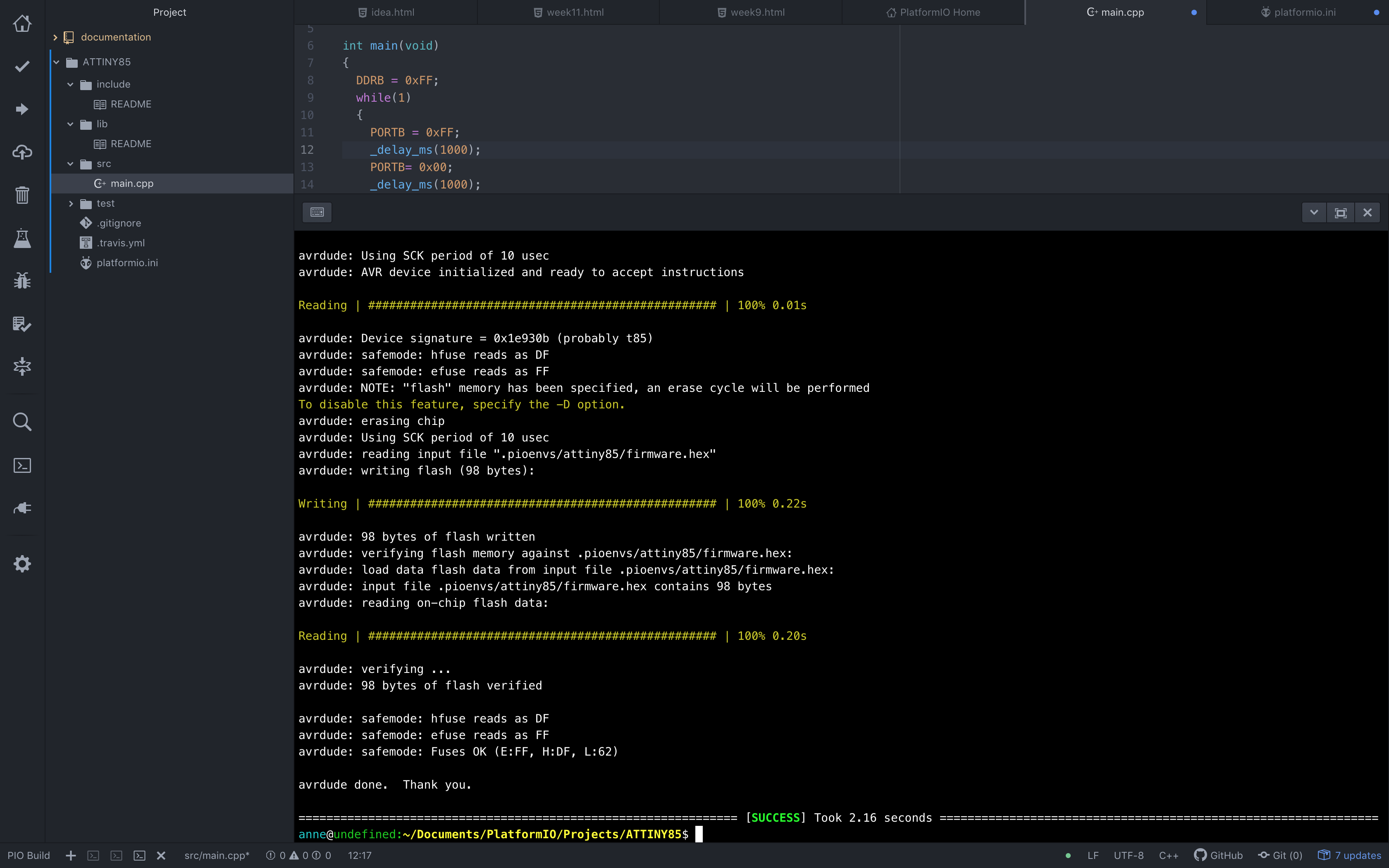
upload_protocol = usbtiny // this tells the computer that we will be using a usbtiny to upload- Now it's time to program a little sketch. Go to the 'main.cpp' file. This file holds the main programm. I used this blink sketch in C to test it out - it blinks forever for 1000 ms on and 1000 ms off, in reality this is a bit off. The sketch switches the whole B register on or off.
#include <avr/io.h> // needed for avr chips
#include <util/delay.h> // import delay library

void loop(){} // must be in any sketch

int main(void)
{
  DDRB = 0xFF;
  while(1)
  {
    PORTB = 0xFF;
    _delay_ms(1000);
    PORTB= 0x00;
    _delay_ms(1000);
  }
}
- Make sure all modified files are saved.
- Connect your board to a USBtiny programmer.
- On the left hand side of PlatformIO open the terminal. Now write the following code in the terminal and press enter. This should compile and upload all files.
platformio run -v -t program
- If all went well the board should start blinking and you should see the following in the terminal.
