8. Computer controlled machining
This week our group assignment is to test run out, alignment, speeds, feeds, and tool paths for our ShopBot machine. With as individual assignment this week to make something big.
Files, planning and tools
Files
Planning
This weeks planning really depends on the ShopBot as we’re with five and each design takes quite a while to cut and it takes even more to set things up. I got a spot on Tuesday afternoon which means I have some more time for the design and to make a smaller prototype. However I’ve got less time to assemble the end result.
- Safety lesson: how to work with the ShopBot
- Group assignment and sharing results
- Make a design
- Make a small prototype
- Redesign based on the prototype
- Setting up my file with PartWorks
- Cutting with the ShopBot
Tools
- Fushion 360
- Slicer for Fushion 360
- Illustrator
- Part Works
- ShopBot console
- Laser cutter
- The ShopBot PRS standard
Link with final project
First I wanted to make a first test shape for my final project, which would probably be something like a tree. This would really fit with the assignment, however when I saw the piece of wood I realized that I wanted to make something more useful. I find it really difficult to go start big without smaller prototyping tests. Therefore it was difficult for me to start with my final project this week. So I decided to make a chair in the shape of leaf, this way it still has a thematic link with my project and it is useful as I really needed an extra chair for on my balcony.
Research and inspiration
For this week I researched different types of chairs and joints. I thought I had a good idea but for this week we only worked within the 2D plane on the ShopBot. I looked mainly into ‘backbone’ type chairs like the Shell chair and the Lusitana chair.
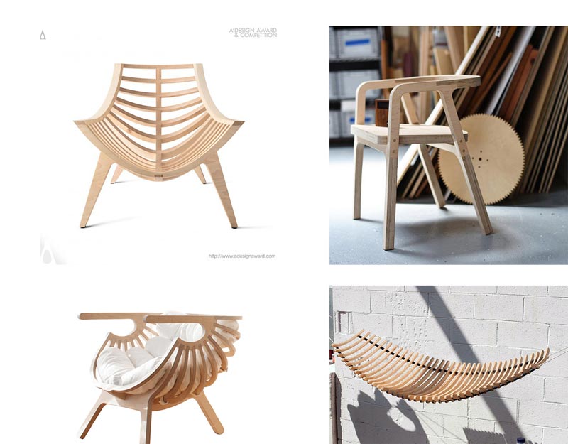 Inspiration for chairs linked to leaf like shapes
links used for inspiration
- Fab Academy student Jonathan Frishberg
- Shell Chair by Branca-Lisboa
- Building a Chair with Shaper
- Lusitana by Paulo Jorge Faias Pereira
What we did – Group assignment step-by-step
On Thursday we tested the machine, luckily Anne from our groups is really familiar with using the ShopBot and how to test the setup of the machine, the joints, the feeds and speeds, depth of cuts. So we made one file with all of these included. Heidi drew it on illustrator while Anne explained to us what would be a good test design. I will describe all the steps for setting up my file and the steps for the machine in my individual part.
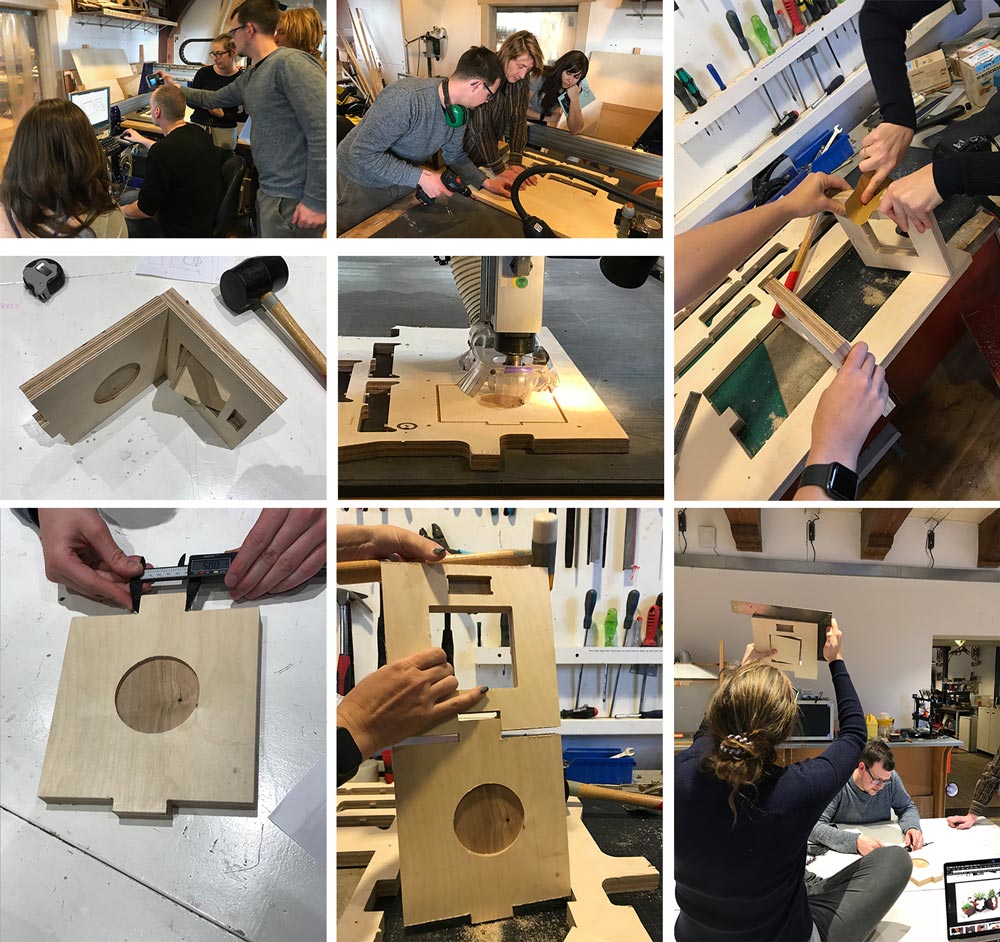 Group assignment machine test
What we wanted to test
- Is is really a square?
- What are the distances between the square and the outside?
- What is the depth of the pocket?
- Is there a difference between the speed setting and the outside line of the square?
- Do the joints fit without an offset?
With this test I was surprised how precise the mill is. I was especially interested in the joints and how this with work with offsets. We just use the same dimensions for the inside as the joint sticking out. This worked well, it’s difficult to connect them, you do need a hammer. But this is exactly what I need for my chair consisting of joints. I used this test for my own design.
What I did – step-by-step
This week I did a lot, it took me a lot of time to design. I prototyped my chair, changed the design, and made the big version.
Designing the chair with Fushion 360
- Design 1: Use the leaf from the 3D week as chair. No depth to sit in. Couldn’t add more thickness while keeping this form. In addition it’s not symmetric and it was really hard to add the symmetry within this shape.
- Design 2: Use sketch and extrude to create shape This kind of worked but the shape looked to simple, it had a clean geometry but it didn’t have a ‘folding’ shape to sit in. Which I really want in my chair. This version is more flat, sitting too straight. It should be possible and easy to change this however I didn’t figure this out.
- Design 3: Starting over again in Skulpt mode. I know how to make a folding leaf within skulpt mode.
- Use symmetry: So I started over again with a patch. Because the problem with my 3D-week design was the symmetry. I first looked if I could add this from the start and I could. So each change on one side would keep the symmetry on the other.
- Look and use inspiration: I used the Lusitana chair as inspiration and mainly as measurement. I knew this chair works so save time figuring out the number I thought I would use this chair as a mock-up version. To check dimensions and measurements.
- I went back and forth within my time line to change shape and thickness of my object. Till I finally had version I thought good enough to create a prototype. In Fushion I only create the sitting part of my chair I wanted to add the legs with illustrator after I slided it with the Fushion 360 slicer. I felt more in control this way.
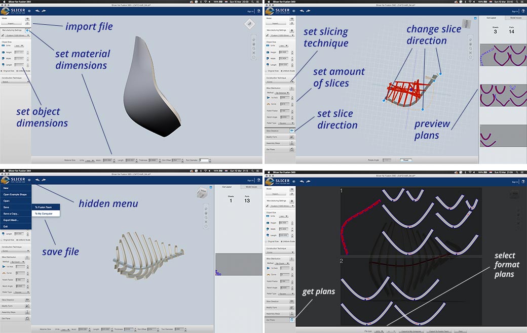
Using Slicer for Fushion 360
To create the shape I wanted I used the Slicer for Fushion 360 tool. I tried to use this tool before when I was working in the Makerslab however I never managed to use it, except for a easy cube to test, as my Fushion 360 files were not good enough. So I wanted to test if it would work this time.
 Setting up my file with Slicer for Fushion 360
Things to keep in mind while using the slicer tool:
- It crashes easily, so make sure to save your file. And create an export as soon as you have a version you like.
- It difficult to get the exact same version back (of course you can you ctrl-z) especially when crashed. Even though you save it, somehow I didn’t manage to get the slices exactly the way I had before. Therefore make many exports.
- The menu for saving your file is a bit hidden under a small arrow on the top left.
- Make sure to set the right dimensions of your material, especially thickness when using joints.
- Double check the sizes and set it on original sizes.
Prototyping my design
For me it was really difficult to start big. So I decided to start small before cutting out a big piece of wood. Therefore I first made two prototypes to get a better understanding of the shape and the construction of my chair. I used the laser cutter for this. And I used Illustrator the convert the file so it would be able to cut. I also used Illustrator to add the legs on my second prototype.
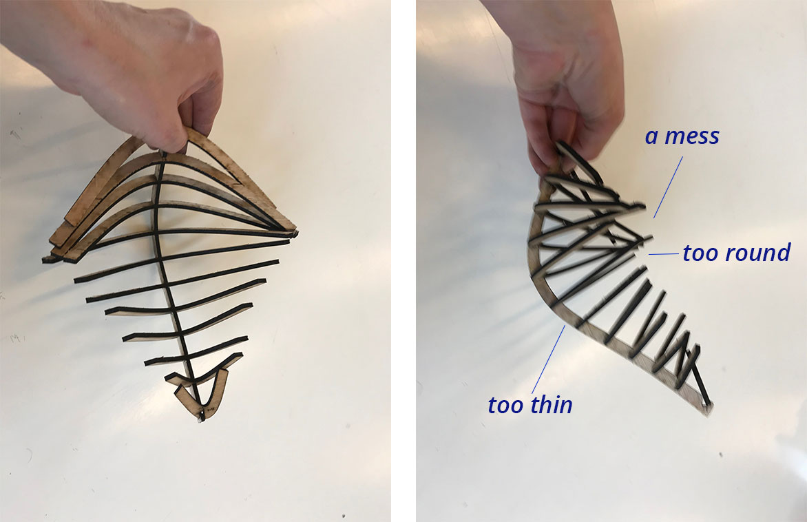
Prototype 1
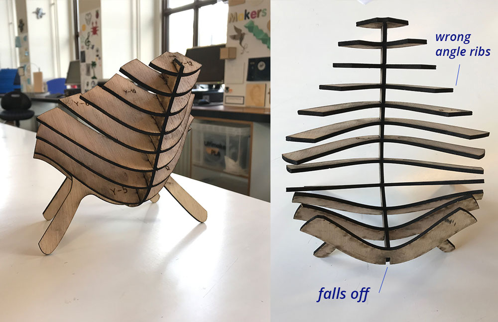
I first made a prototype of my first version with the sitting part without legs. As you can see the backbone and the sides are way too thin and the nerves nest into each other which makes a mess. And the veins are too round, this doesn’t really make a leaf like shape.
 First prototype of my chair
Prototype 2
For the second prototype, I went back to Fushion 360 and thickened my leaf. In addition I added a curve to get a more natural lobe of the leaf.
 Second prototype of my chair
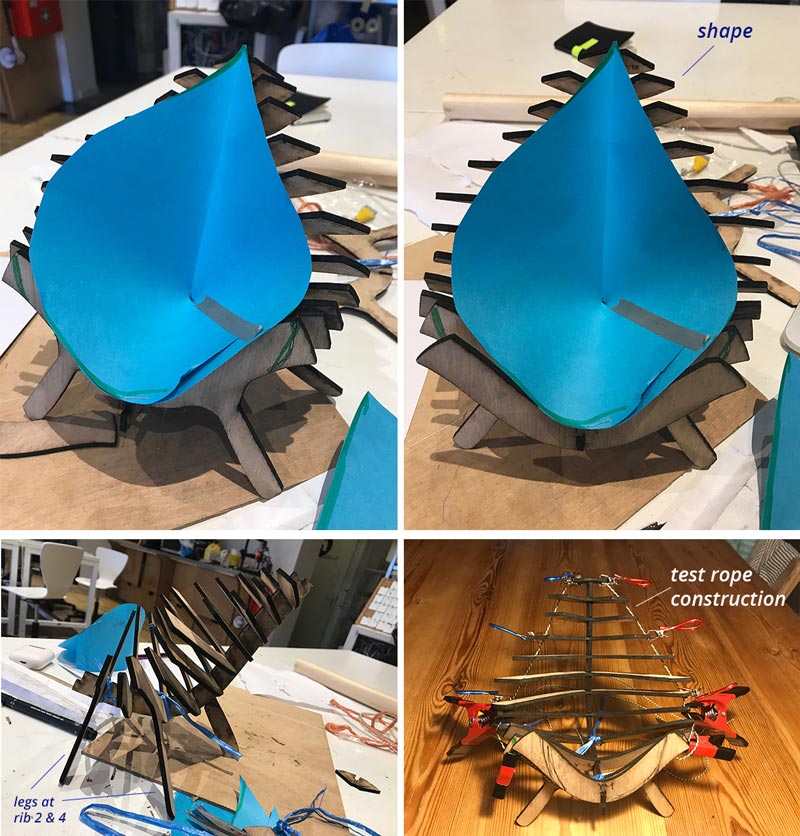
With my second prototype I did some tests.
Shape of the leaf Ruud of the Waag gave me great advise to use a piece of paper to create the inside shape I want. Than I can use this shape to adjust my design. With the leaf inside I could see that the inside corner points were actually at the right spot. However the outside points where in the wrong angle and should go more to the back.
Placement of the legs I used the back legs to check the right place for the best construction stability. I designed it on the sixth slot however in the end I choose to use the fourth as this seemed a better construction.
Using a rope for stability I wanted to make a wooded outside like theLusitana chair, this would mean however that I had to bend wood. Which would be possible with a kerf. But I didn’t have time to figure out this would work best. So In the end I did some tests with the stability of the chair using a rope system, like the hammock of 2017 Fab Academy student Jonathan Frishberg. This seems to give more stability but in the end I didn’t use it for the final version.
 Tests with my second prototype of the chair
Finishing the design
After my tests with my prototype I had a list of things I wanted to change or had to consider. Time and material wise I couldn’t do all.
- Changing the shape of the veins of the chair so it looks more like a leaf.
- Making sure the legs are the right length.
- Adding an extra leg on the back for stability in the construction.
- Using rope on the side for stability and aesthetics.
- Changing the shape of the veins so it would function more as a chair and there would be place to sit.
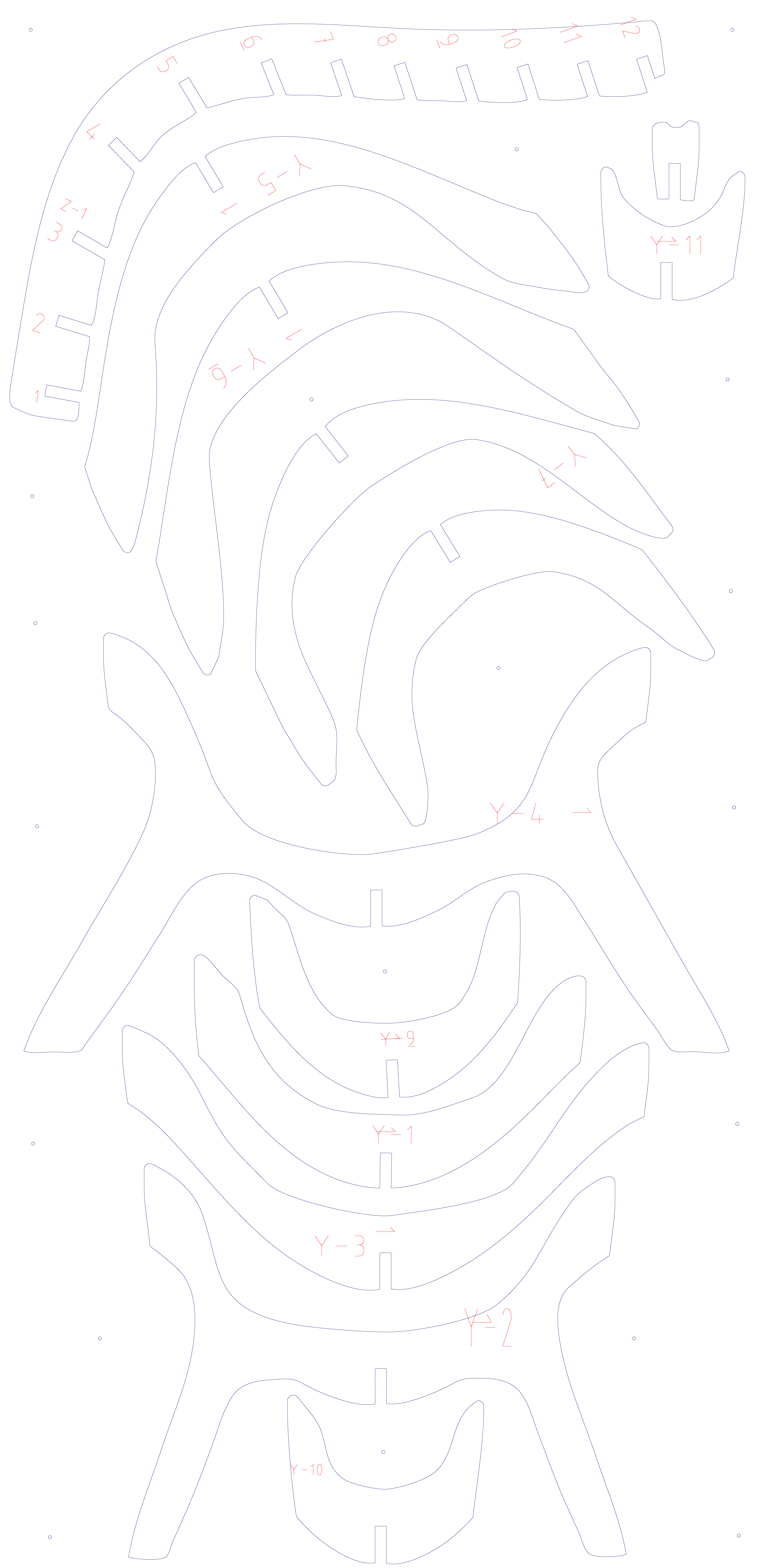
In the end I did change the design of the veins (step 1 and 5) and I double checked the length and placement of the legs. I didn’t do step 3 because there was no time left to go and get good rope. I would like to do more tests with this option and I didn’t do step 4, mainly because it wouldn’t fit on my material. But I also thought design wise it didn’t look nice.
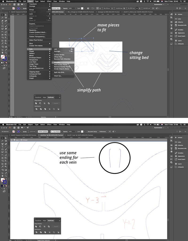 Redesign of my chair in illustrator
This redesign was really quick and dirty with Illustrator as this was the fastest way I knew I could work and change these part in one night. In the end I manage to fit everything on my board of 250 cm by 122 cm.
 Redesign of my chair in illustrator
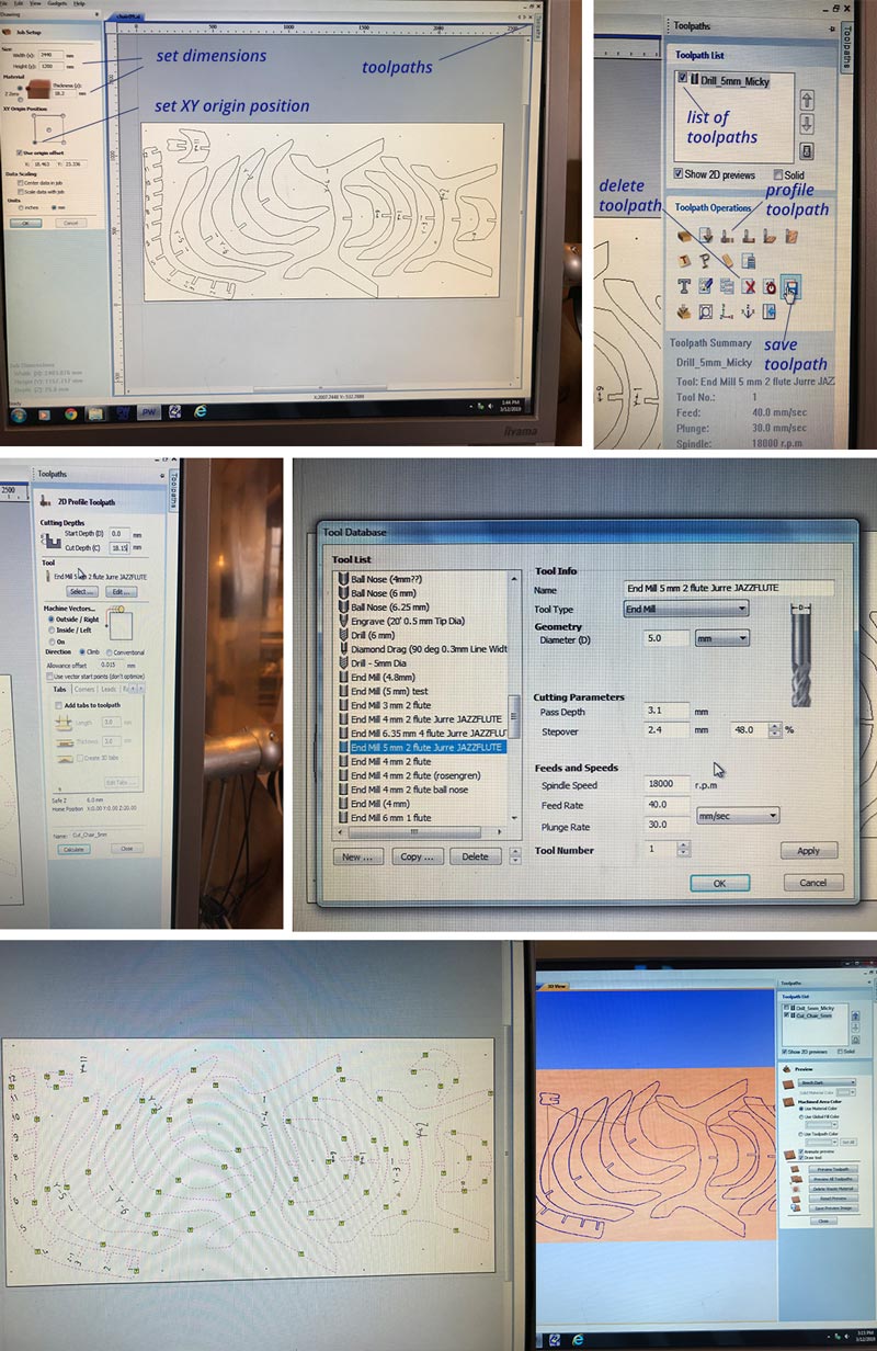
Preparing the files for the ShopBot
At Waag we use PartWorks to prepare our files for the ShopBot. Henk gave us an instruction how to use this. You open your file in the program. And follow each step. Make sure to set the right thickness. I had some doubts about this because my material was on one side 17.8 mm and on the other 18.2 mm. In the end I used a thickness of 18.15 to make sure I wouldn’t cut through into the sacrificial layer on one part and it was still thin enough to remove on the other part.
Don’t forget while setting up PartWork:
- Double check dimensions and thickness.
- Save your file and the toolpath.
- Don’t forget to add tabs to make sure you don’t have pieces of wood flying around while milling.
- Adding dogbones is under the fillet option on the menu on the right.
- Check with preview what the machine is doing.
 Setting up my file with PartWork for the ShopBot
Settings used
I used the setting for speed and feed the same as Joey and Heidi. As these seemed to work.
** End mill** Diameter: 5 mm - 2 flute
Cutting parameters Pass depth: 3.1 mm (make sure it’s easy to divide this number with the thickness of your material) Stepover: 2.4 mm and 48%
Feeds and Speeds Spindle speed: 18000 r.p.m. Feed Rate: 40.0 mm/sec Plunge Rate: 30.0 mm/sec
Starting the ShopBot
Joey gave me the advise to write down a to do list to make sure you don’t forget any of the steps to set up the ShopBot. I followed the list he gave and the notes I’ve written with the explanation by Henk.
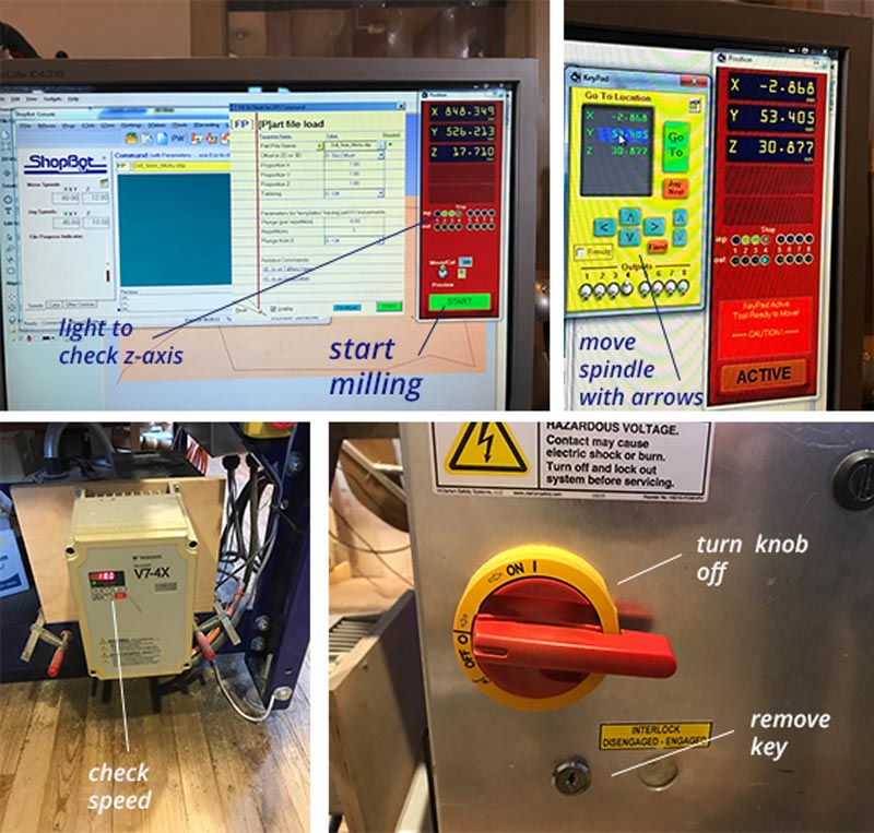 Starting the ShopBot
- Turn on the dust extractor at the back of the room.
- Turn the machine on, don’t turn the mill on yet.
- Launch ShopBot software.
- First calibrate x and y. Set it at the machine origin and move with (k) key to my own origin. Click zero on menu bar and select zero (x,y) and don’t forget to take a picture at this moment! to make sure you have your origin.
- Next calibrate the z axis. First check with iron plate on the left of the nozzle if the mill recognizes it. By moving under it and checking if the first light on the screen blinks. Lay it down under the mill and click z-axis. Now it will measure the z. Make sure the iron plate is place underneath so it won’t go through.
- Open the screw hole drilling file.
- Start the machine with turning the key. The spindle starts, check if the speed is set on 18.000 and make sure to put the dust bag on with the red button on the side.
- Wait till it’s finished milling the screw holes. Turn off the spindle and the dust extractor.
- Set screws with the drill.
- Re-calibrate the z-axis as this might have changed with fixing the screws.
- Double check with the picture you to the origin is at the same spot as your first milling job.
- Open the file with the cut outs of the design.
- Turn on the spindle and the dust extractor.
- Start the file and the milling of the cut out.
- Stay alert especially near screw holes and each new part.
End result: a chair
I didn’t sand the chair yet and I didn’t put it together yet, but I did try it how it would fit. And the joints are perfect, a bit tight but they fit and make a strong connection. So I first have to make it nice and sanded before putting it together. To get an idea I did set everything up and I did connect the joints of the legs so I could see if I could sit on it for my hero shot. And I could!
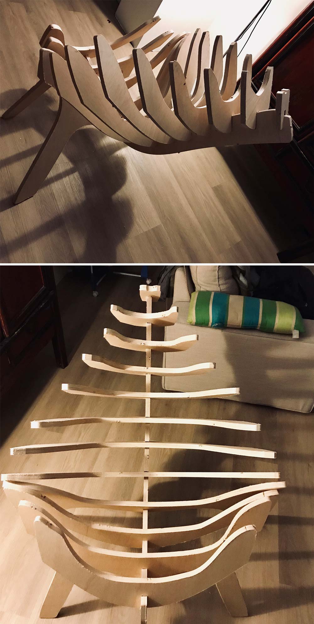 End Result
What I did wrong – and how I solved it
My biggest struggle this week was my design and my own character. I found it really difficult to make something big in just one week.
I took the wrong picture for the origin
After milling the screw holes and fixing the plate on the sacrificial layer and wanted to start my cut out design. Because I moved the spindle around Henk thought I might have set it back at the machine 0,0. So we wanted to double check this with selecting my origin. But when the spindle moved to the origin I was totally sure if it was a the right place. Henk pressed the x and y axis calibration while I didn’t realize this would reset the x and y. So I looked back in my picture history and I had a lot of pictures of the x and y setting but all from the wrong moment. I forgot to make a picture when I set the x and y axis.
How I solved it?
while checking the screw and measuring the design we recalculated the origin. However in the end it was the exact origin so I had to double check for each screw it wouldn’t touch the mill. And in the end one of the smaller pieces fall off the plate. But this didn’t have a lot of effect on the design. So I managed to fix it.
My own expectations
For this week I found it very difficult to lower my own expectations because somehow making something big meant for me it had to be useful and perfect. Otherwise it would be a shame for the amount of wood we used. I was mainly struggling while designing, it was a bit frustrating as my Fushion 360 skills weren’t as quick as I wanted to go. And Slicer kept crashing.
How I solved it:
Not sure I did. But what helped in the end was to set my priorities, based on time and my own possibilities.
- First of all make sure you can sit on the chair size wise, so I changed the sitting bed.
- Make sure the construction is strong enough to sit. In the end I decided not to add and extra leg.
- Try to find different solutions for the construction. I did think of adding a rope construction however in the end I decided not to do this time wise.
What I learned
This week I learned a lot about myself, setting priorities and making sure to have the right expectations. I also learned more about designing in Fushion 360. I’m still figuring out how to work with a 3D program. I made a lot of different versions and tried out a lot of ways to get the end result I want. In the end I still feel it’s all a bit shoestring.
What made me proud!
I made a chair this week!
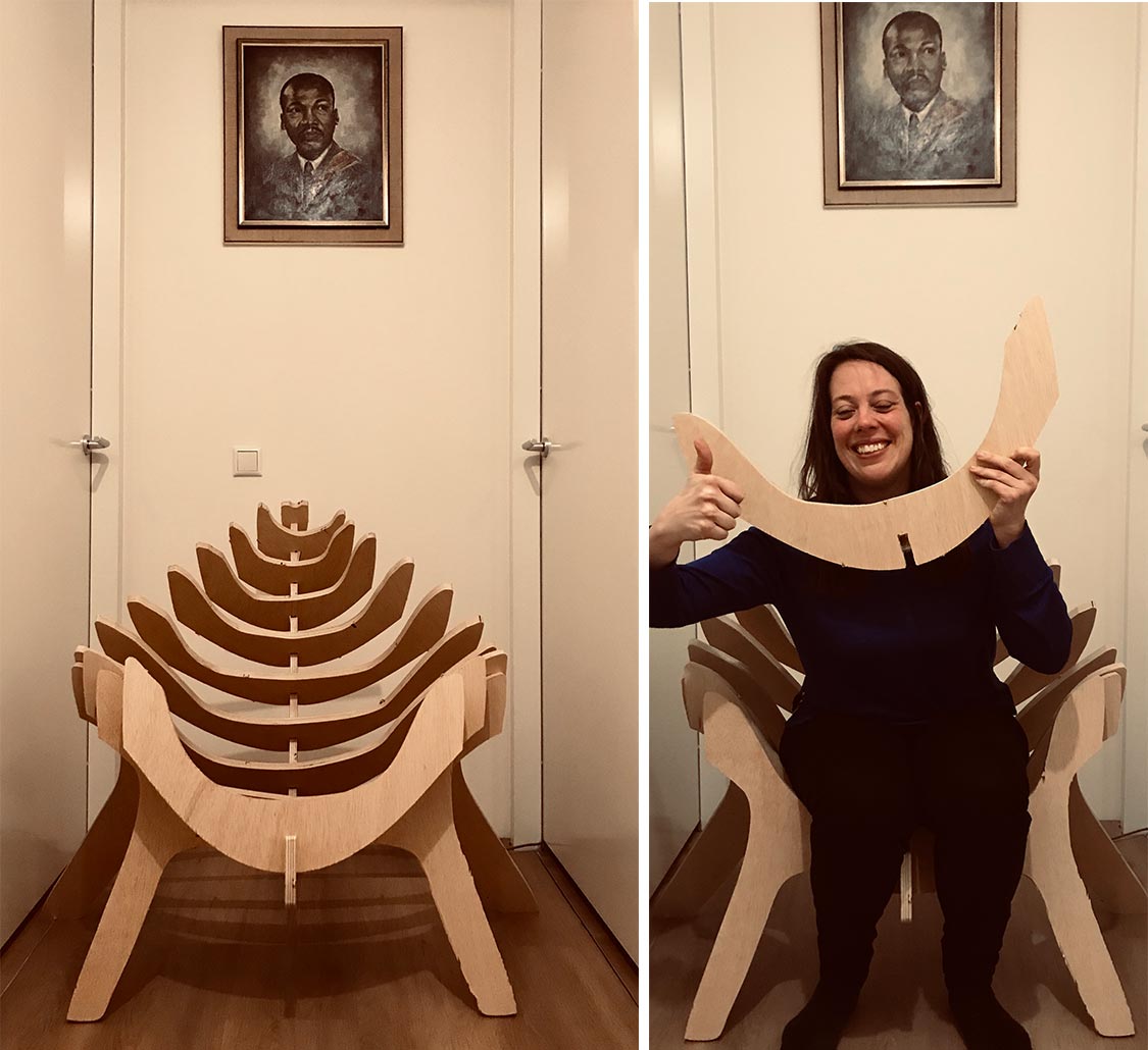 hero shot!
Credits and references
This week I got a lot of inspiration and advise from a lot of different people. First of all Klaas-jan helped me a lot with trouble shooting and brainstorming my idea. Sander and Cees of the Makerslab helped me brainstorm about the construction when I made my first two prototypes on the laser. Ruud of the Waag gave me useful advise about the construction of chairs in general and my chair. And off course my fellow Fab Academy students really helped out this week with ideas, sharing setups, and helping each other out.