9. Embedded programming
This weeks individual assignment is to read the datasheet of the ATTiny44, program my board to do something, with as many different programming languages and programming environments as possible. The group assignment is to compare the performance and development work flows for other architectures
Files, planning and tools
Files
- Team assignment comparing architectures
- Red LED blinking with button click
- Serial communication test with sensor values
- Link to Neils Make file used
- Reverse Case make file
- Reverse Case c file
- Blink CPP-file
Planning
This week my planning is a bit more difficult as I will be on a trip for a week.
- Group assignment and its documentation
- Read the datasheet
- Understand what the datasheet is and how it works, document this.
- Program my board, first with the Hello Echo Board program
- Try to change the hello echo program and program something myself
- Try a different programming environment and language to program my board
Tools
- Hello Echo board and FABtinyUSB
- USB 2.0 Hub
- Arduino IDE
- FTDI board and cable
- Terminal
- Mods
- Roland Modela MDX-20
Link with final project
This weeks assignment is not directly linked with my final project. However I’ll need to be able to program my board and other boards to come to be able to create my interactive tree. Therefore I will try to link reading the datasheet to the questions I have about possible interactions for my final project.
Research and inspiration
This week I didn’t have much time for the assignment as I was away for a week. I mainly researched some tutorials about how to use the Arduino IDE. You can find the links below.
Links to datasheets
Links to tutorials used
- Arduino tutorial: Secrets of Arduino PWM
- Arduino: syntax #define
- Arduino tutorial serial communication
- Easy install PIP
- USB to UART bridge VCP driver
- Damalis boards manager ATtiny
- C operators
- Ascii table
What we did – Group assignment step-by-step
For the group assignment we compared different types of architecture with each other, We divided four different ones amongst each other. We looked into their performance (voltage, chip architecture, (clock)speed, memory, pins, and other special features) and their work flow (connecting and programming the device). We collected this information from the datasheets and shared it with each other in a spread sheet.
For this comparison we used the:
- Makey Makey classic v1.2(Micky and Joey)
- ESP8266(Micky and Joey)
- SE555(Rutger)
- Raspberry pi zero(Anne and Heidi)
The full comparison](https://docs.google.com/spreadsheets/d/1s-x6rIQSbsaGlAkQPWj40Db1WL3mfsgzheXziJWCPmY/edit#gid=0)
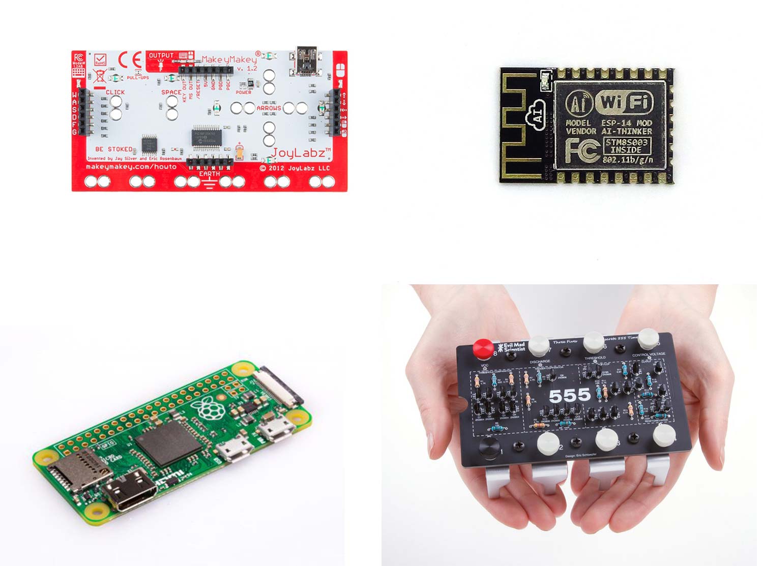 Group assignment: comparing the Makey Makey, ESP8266, Raspberry pi Zero and SE555
When we compare these architectures with each other we can see that they each have their own specific functionalities. The 555 is really simple and only has a few functions, eight pins and no memory. The 555 version by Evil Mad Scienist Rutger looked at is a fun example to use for educational purposes for children. Like the Makey Makey, which is exciting to use because you can a button out of everything! The different ports, and the USB connection on the Makey Makey make this a happy feature. In addition the PIC micro-controller, that can be found in the Makey Makey, is powerful and simple in use.
The ESP8266 does not have the USB possibilities as the Makey Makey but it does have two serial ports for communication as well as 2.4GHz WIFI support. It also has on board memory of 4 megabytes, this makes it possible to run a small web server on the chip. The final one we compared is the Raspberry Pi Zero which is a full computer. So we went from very simple to a much more complex architecture in this group assignment. The ARM chip inside the Raspberry Pi Zero is a microprocessor which is more powerful and therefore you have more possibilities than with a micro-controller. It has full WIFI support (2.4GHz as well as 5GHz) and Bluetooth 4. Because Raspberry Pi Zero has a microprocessor an operating system is needed, which is its on version of Linux build in it. You can use it for simple and more complex projects, it runs Python, C and other languages.
What I did – step-by-step
For this weeks assignment I kept it easy and simple because I was away on a trip for the full week and because I’m not so experienced with programming. Time wise I decided to keep this week simple.
Reading the datasheet
I already used the datasheet in week 7 to check if I could add an extra green LED to pin number 5. I found it difficult to start reading the datasheet without having questions or knowing which questions I could get answers to in the datasheet. My goal is mainly to know where to find the relevant information in the datasheet and understand what they mean. Therefore I want to know what each chapter is about, this way I can more easily find each specific section. By trying to understand the table of contents I hope it gives more grip on the Attiny 44 and how to use a datasheet. The practice of reading a datasheet this week really helped me in the Output Devices week. As you can read in my documentation of week 12 I used ctrl+F to look up the names of the registers of the ATtiny85 in the ATmega 328P (Arduino Uno) datasheet, this way I could find the names of the registers I needed to get my code to work for the Arduino Uno. More details on this can be found in my documention.
Features
The datasheet of the ATtiny44 by Atmel starts with an overview of its features.
 Features of the ATtiny44 as shown in the datasheet
This list of features shows that the Microcontroller has high performance and is low in power. It’s an 8-bit Microcontroller with an RISC (Reduced Instruction Set Computer) architecture. It has high endurance, non-volatile memory segments. Which means that it lasts long (100 years at 25 degrees Celsius) and it retains data even if there is a break in the power supply. The Peripheral Features show that the Microcontroller has different types of timers and counters. It has ADC (analog-to-digital converter) channels which means it can convert an analog signal to a digital one and it has an Universal Serial Interface which means it has pins for serial communication. The Special Microcontroller Features show is has an debugWIRE system, which is a serial communications protocol, designed by Atmel. This can be used for on-chip debugging. In-system programming is possible through the SPI port. I will use the FABtinyISP programmer for this. Other interesting features are the internal calibrated oscillator and the on-chip temperature sensor. I/O and Packages mentions it has twelve programmable Input and Output (I/O) lines. The operating voltage is 1.8 to 5.5 Volt. The Speed Grade is: 0 - 4 MHz at 1.8 - 5.5V / 0 - 10 MHz at 2.7 - 5.5V and 0 - 20 MHz at 4.5 - 5.5V. The industrial temperature ranges from -40 to +85 degreed Celsius. And it shows that the low power consumption in active, idle and power-down mode.
1. Pin Configurations
This chapter shows a diagram of the Microcontroller and each pin. It also shows how the pins are named within different systems. In addition it gives a description of each pin. That way you can find out which pin supplies voltage (VCC), is ground (GND), Reset, which pins are digital or analog and which ones are I/O ports.
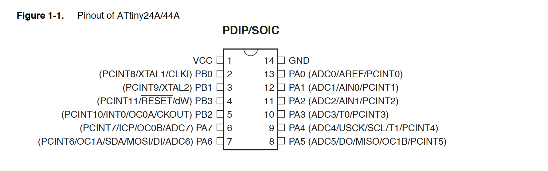 Diagram of Pinout ATtiny44
2. Overview
The overview chapter provides a full description of the chip. It’s a written out summary of the features list including a block diagram. This diagram visually shows how the different features are place within the ATtiny44. What I find really useful is that it also show each feature and it provides more information for each of the pin number ranges.
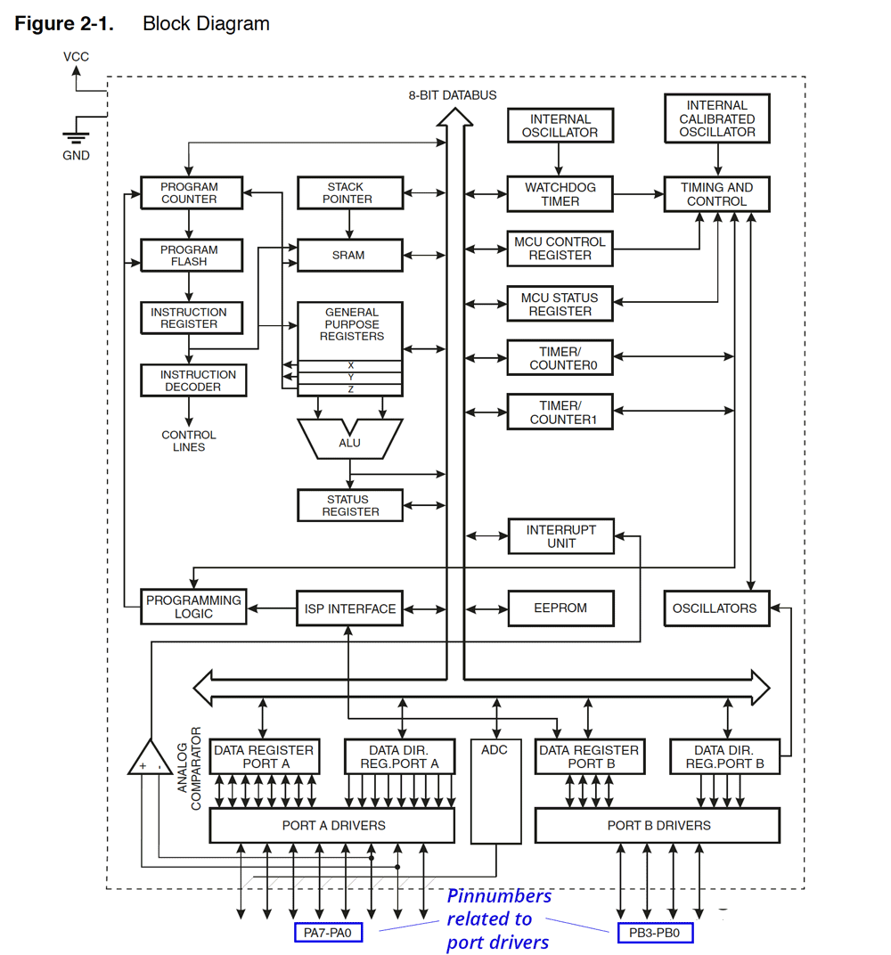 Block diagram of ATtiny44
3. About
This chapter shows where to find more resources and documentation.
4. CPU Core
As described in the datasheet this chapter discusses the AVR core architecture in general. The main function of the CPU (Central Processing Unit) core is to ensure correct program execution. This section therefore describes how The CPU is able to access memories, perform calculations, control peripherals, and handle interrupts.
5. Memories
This chapter talks about the different types of memory in the ATtiny44. It shows that the AVR Architecture already has two main memory spaces: the Data memory and the Program memory space. In addition, there is an EEPROM Memory for data storage. All three memories are linear and regular. I can use this section if I want to figure out how to use the memory of the ATtiny44. It includes example code, which is useful.
6. Clock System
The section on clock system shows the clock distribution with the use of a diagram. It mentions that not all clocks need to be active a given time. This section is interesting because the hello echo board as an external clock of 20 MHz. Therefore I wanted to understand a bit more about the external clock however I’m not sure what it means that: “To run the device on an external clock, the CKSEL Fuses must be programmed to 0000”. But I guess that to able to use the external clock on the Hello Echo Board I will need to program Fuses in such a way that it know it has to use the external clock in stead of the internal one. I think in the Arduino IDE I do this in the tools menu.
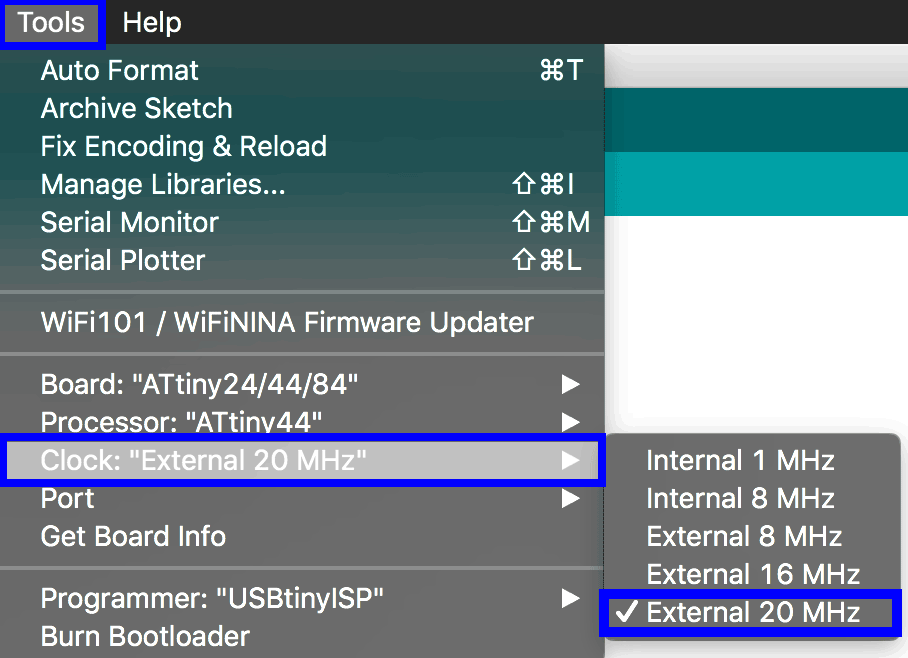 External clock settings Arduino IDE
7. Power Management and Sleep mode
As mentioned before the ATtiny44 is low in power. This section show how to make efficient use of the power modes within the Microcontroller. There are various ways to save power, for example using sleep mode shuts down unused modules in the ATtiny44. There are different ways to tailor the power consumption of the Microcontroller. This chapter shows different diagrams and ways how to use sleep mode, stand-by mode, and power-down.
8. System Control and Reset
This section discusses how to use the different reset options internal and external. I found the term watchdog timer interesting. As I never heard it before. It “is an electronic timer that is used to detect and recover from computer malfunctions. During normal operation, the computer regularly resets the watchdog timer to prevent it from elapsing, or ‘timing out’” as mentioned on its Wikipedia page. As I can see in the pin schedule and what I remember from week 7 is that pin 4 is the RESET pin.
9. Interrupts
This section is useful to know more about the specifics of the interrupt handling as it is performed in the ATtiny44. It shows the reset and interrupt vectors. These “Interrupt vectors are addresses that inform the interrupt handler as to where to find the ISR (interrupt service routine, also called interrupt service procedure)” (Zhang, 2010).
10. I/O ports
The AVR ports on the ATtiny44 have true Read-Modify-Write functionality when they are used a general digital Input/Output ports. This means that they can both read a memory location and write a new value into it simultaneously, either with a completely new value or some function of the previous value as mentioned on Wikipedia. This also means that the direction of one port pin can be changed without unintentionally changing the direction of any other pin. I will need this chapter in the coming weeks when we talk about Input and Output. It shows the general use as digital I/O pins as well as the alternate port functions.
11. 8-bit Timer/Counter0 with PWM
A timer/counter measures the elapsed time by counting processor clock ticks. The 8-bit Timer/counter allows accurate program execution timing and wave generation. It has PWM support where PWM means Pulse With Modulation which is a technique for getting analog results with digital means. An example is fading an LED.
12. 16-bit Timer/Counter1
The 16-bit Timer/Counter allows signal timing measurements in addition to the accurate program execution timing and wave generation.
13. Timer/Counter Prescaler
This section describes the different prescaler settings for the Timer/Counter0 and Timer/Counter1. As I didn’t know what a prescaler means I looked it up on Wikipedia: “A prescaler is an electronic counting circuit used to reduce a high frequency electrical signal to a lower frequency by integer division. The prescaler takes the basic timer clock frequency (which may be the CPU clock frequency or may be some higher or lower frequency) and divides it by some value before feeding it to the timer, according to how the prescaler register(s) are configured.”
14. USI - Universal Serial Interface
The Universal Serial Interface (USI) of the ATtiny44 provides the basic hardware resources for serial communication. The USI is useful because this way I can communicate with the Microcontroller. For the assignment for this week I used the Serial Communication to read the measurements of the photo transistor. In addition, I used the serial communication for Neils hello.ftdi.44.echo.c program.
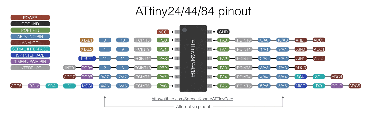 The turquoise tags shows the Serial Interface Pins
15. Analog Comparator
As mentioned in the datasheet “the analog comparator compares the input values on the positive pin AIN0 and negative pin AIN1. When the voltage on the positive pin AIN0 is higher than the voltage on the negative pin AIN1, the Analog Comparator Output, ACO, is set.”
16. Analog to Digital Converter
The analog to digital converter is very useful for my projects. It can convert an analog signal into a digital system. The ATtiny44 has 7 ADC pins (pin 6 to 13). This section further describes more in detail how to use the different features realated to the ADC.
17. debugWIRE On-Chip Debug System
The debugWIRE on-chip debug system uses a One-wire, bi-directional interface to control the program flow, execute AVR instructions in the CPU and to program the different non-volatile memories. The debugWIRE communication pin is physically located on the same pin as external reset.
18. Self-Programming the Flash
This section shows how to program the flash. I think this section will be useful for me. As far as I understand the Make file of Neil uses the Flash as it stores the character in a buffer. This chapter mentions how to use the buffer and how to program
19. Memory Programming
This section describes the different methods for programming the ATTiny44 memories
20. Electrical Characteristics
This section shows all the electrical characteristics of the chips. It provides a clear overview of the specific characteristics of each part.
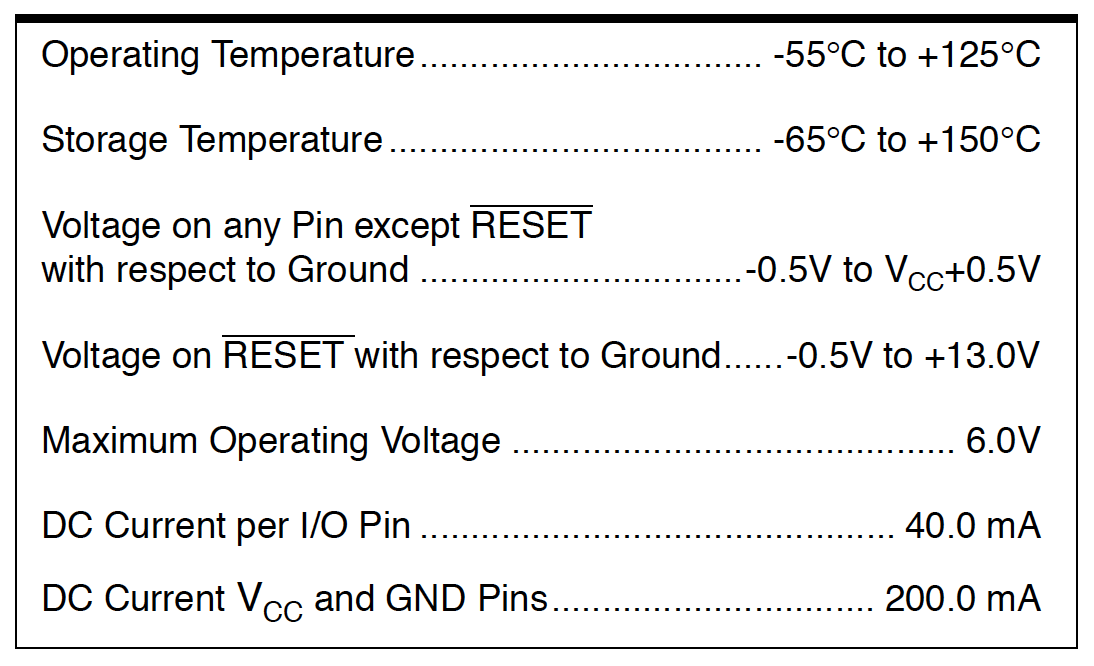 Electrical Characteristics of the ATtiny44
21. Typical Characteristics
This sections shows different graphs of simulations and characterization of similar devices and design methods. So the data should be treated as an indication. The graphs show the supply current, speed and consumption of the chips. For example the supply current of the I/O modules, the active, idle, power-down and standby supply current and the internal oscillator speed.
Chapter 22 to 27 of the datasheet provide practical summaries of the register and instruction set as well as more information about packaging and ordering.
Programming my board
Before I’m able to program my board I have to setup the Arduino environment for the ATtiny44 and I have to bootload the chip. In the preference menu I select Show verbose output during: compilation and upload. This provides more information while compiling and uploading my program. In addition I add the link to David Mellis ATtiny boards manager in the preference menu.
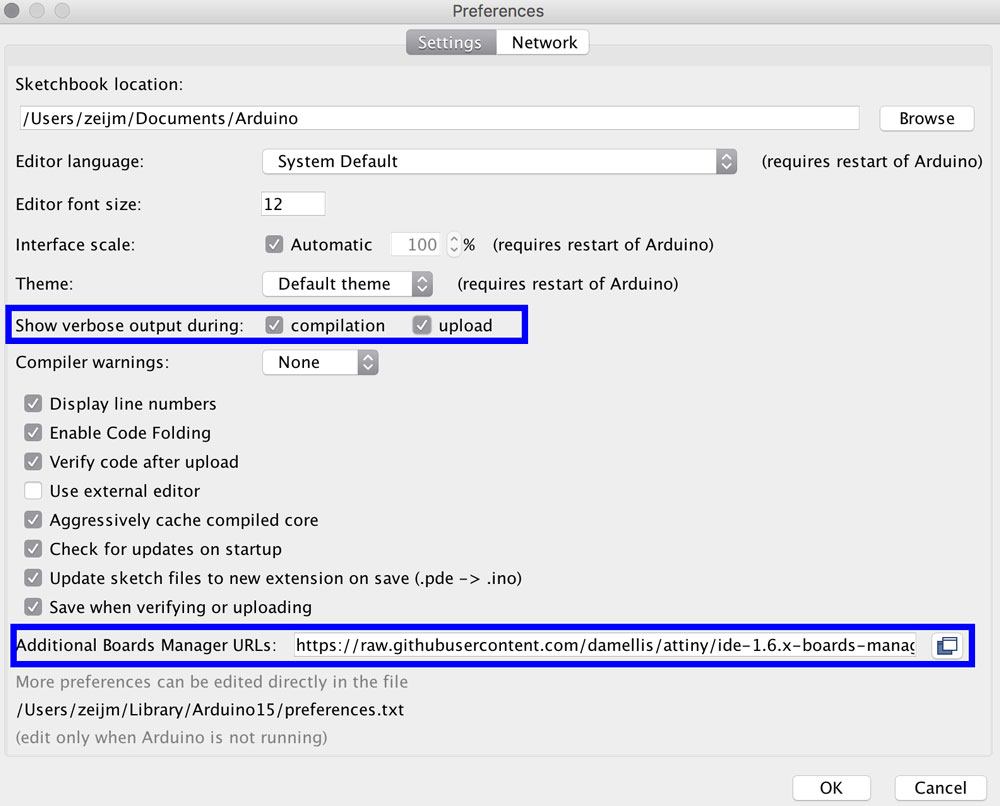 Arduino preference menu
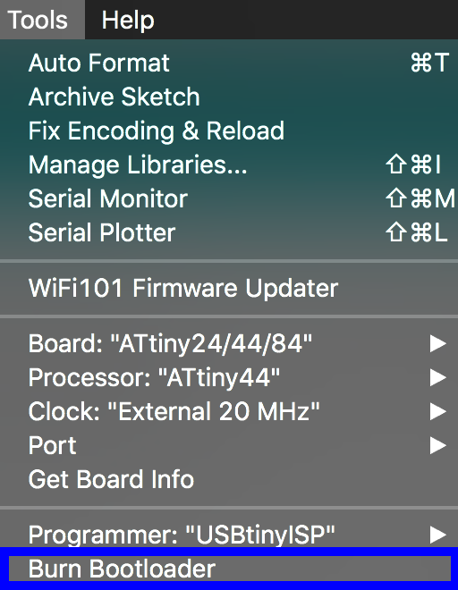
Step 1: Burning the bootloader
The bootloader contains a map of the chip, it sets all the transistors in the right state and it put the IC in programming mode. Before I’m able to burn the bootloader, I first have to setup my microcontroller in the Arduino IDE. I added the boards manager by David Mellis in the preference menu now I’m able to install the latest version in the boards manager menu. This gives more options in the Tools menu, and I’m able to select my processor the ATtiny44, the external clock of 20MHz and I select the USBtinyISP as programmer.
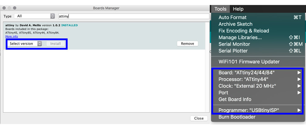 Arduino boards manager
The next step is to connect the USBtinyISP to the Hello Echo Board with the wire. And I connect my USBtinyISP with the USB2.0 hub to my computer. I use the USBtinyISP as programmer. The only thing I have to do is click on the burn bootloader in the Arduino menu. This worked like a charm, not problems.
 Arduino IDE burn bootloader
Step 2: writing a program in the Arduino IDE
For my first program I started with a basic example we worked on on Thursday with Henk and which was modified by Joey. I combined this into my own version. I changed the beginning state of the RED light so it’s on when the button is not pressed. When I press the button it will start to blink on and off.
// found here: https://arduino.stackexchange.com/questions/3479/how-to-toggle-led-on-button-press
// First version is by Joey, I modified it and changed the code by adding a different blinking rythm.


int ledPin = 7;  // This is the pin of the ATtiny44 connected to the REDled
int buttonPin = 3; // This is the pin of the ATtiny44 connected to the button
int buttonState = 0;


void setup() {
// Here I setup the pins and tell them what their 'state' is.

pinMode(ledPin, OUTPUT);
pinMode(buttonPin, INPUT_PULLUP);
}

void loop(){
  // This gets the current state of the button
  buttonState = digitalRead(buttonPin);

  // This checks if there is a difference in the button state, did I push it? if so than it will blink on and of with a delay of 50.
 if (buttonState == LOW) {
     // Switch the state of the output
  digitalWrite(ledPin, HIGH);
  delay (50);
  digitalWrite(ledPin, LOW);
  delay (50);
  digitalWrite(ledPin, HIGH);
  delay(50);
 }
    else {
       digitalWrite(ledPin, HIGH); // If the button is not pressed the RED light is on.

  }

}
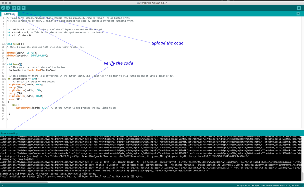 Arduino IDE verify and upload code
Before loading the program on my hello echo board I first verify the code with the check mark. If there’s something wrong in the code it shows in field on the bottom of the page. When the code is compiled you see how ‘big it is’ and how much memory it uses. When the code is all checked and verified I can upload it to my board:
- Connect USBtinyISP to the USB2.0 HUB
- Connect the USBtinyISP to the Hello Echo Board
- Click on the Arrrow on the Arduino IDE, the upload starts. If something goes wrong it will show in the message window on the bottom. This time everything went smooth and it worked straight away.
- The red LED is on, this means that the program works. To double check I clicked the button and the light started blinking.
Blinking led on button push
Step 3: testing serial communication
To test the serial communication and make use of the photo transistor we used the code below for a test. Important settings to remember when using serial communication in the Arduino IDE:
- Include a serial library otherwise you won’t be able to communicate with the board. This is set on the top with the #include tags. Within these tags you also define the receive and transmit pin.
- Make sure to set the right pins to the sensor.
- Make sure to add the serial.begin(9600).
- Use the ISP programmer to load your program but make sure to remove the programmer when you connect the FTDI cable. Because I didn’t desolder the blob (as documented in week 7) it can cause a short.
- Use the FTDI for the Serial communication. Double check if you connect the right pin with the right pin. It’s a bit confusing because RX needs the be connected to TX and visa versa.
//I created this code during the group assignment. Henk provided us with this setup.

#include <SoftwareSerial.h> // import another program, a library, to communicate
#define rxPin  0 // this is similar to the int = setting, however this is linked to the library
#define txPin  1

SoftwareSerial serial(rxPin, txPin);

int pin_L_sensor = 2;
int value_L_sensor = 0;


void setup() {
  // put your setup code here, to run once:

  pinMode(rxPin, INPUT);
  pinMode(txPin, OUTPUT);
  pinMode(pin_L_sensor, INPUT);
  serial.begin(9600);

}

void loop() {
  // put your main code here, to run repeatedly:
  value_L_sensor = analogRead(pin_L_sensor);

  serial.print("the status of the sensor is: ");
  serial.println(value_L_sensor);
  delay(1000);
}
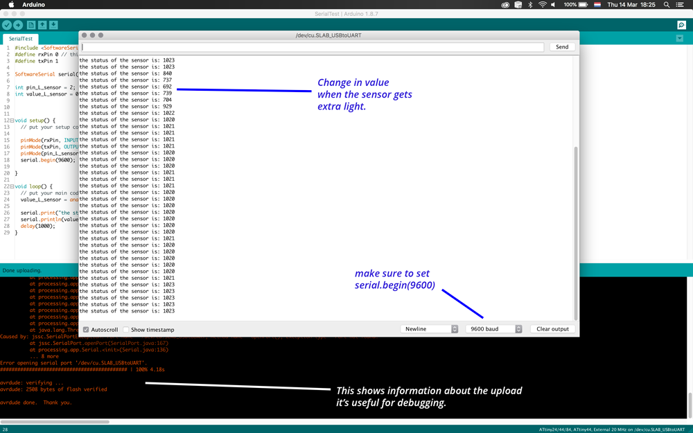 Serial Communication with photo transistor values
Step 4: programming my board using Neils Hello Echo file
To try out a different environment and programming language I used the Make files by Neil and the instructions provided on the fabacademy site to test if I could also program my board through the terminal.
- I downloaded the hello.ftdi.44.echo.c.make files on my computer.
- I used the link to programming on the Fabacademy site for the terminal commands.
- First make hex file: use command make:
make -f hello.ftdi.44.echo.c.makeThis creates hex file - After this I programmed the fuses using
sudo make -f hello.ftdi.44.echo.c.make program-usbtiny-fuses - To than program the hex file onto my board I used
sudo make -f hello.ftdi.44.echo.c.make program-usbtiny - Because the communication didn’t work, the error message showed something went wrong with python. I thought it was already installed on the Mac. It is but I still had to install the package manager for Python PIP. I followed the instructions by Peter Mortenson on Stackoverflow
- To set up the serial communication I used the command
python term.py /dev/cu.SLAB_USBtoUART 115200make sure to add /dev/cu.SLAB_USBtoUART when using the Mac. The instructions provided by the Fabacademy use the port name as it is mentioned in Linux.
 Result of Neils hello echo make file with my own board
Step 5: changing the Hello Echo file
I wanted to understand the hello echo file by changing it myself. My goal is to change all uppercases to lowercases and the other way around.
- To do this I needed to add an function in the while function of Neils code.
- I used the ASCII table to check which decimals are lower case and which ones are higher case. Decimals 65 to 90 are higher case and 95 and 122 are lower case.
- I added 32 to the value of chr for the higher cases and subtracted 32 of the value of chr for the lower cases.
- I save this file under a different name hello.ftdi.44.echoReverseCase.c.
- Because the make file is linked to this c-file I also had to change the name ofe the make file into hello.ftdi.44.echoReverseCase.c.make and I added hello.ftdi.44.echoReverseCase in the make file after project=
- When I changed all this I followed the same commands as before only with my new file name.
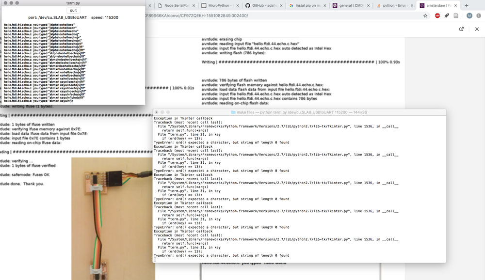
- I typed hello in lower case and WORLD in upper case. As you can see in the screenshot the term.py displayed it the other way around.
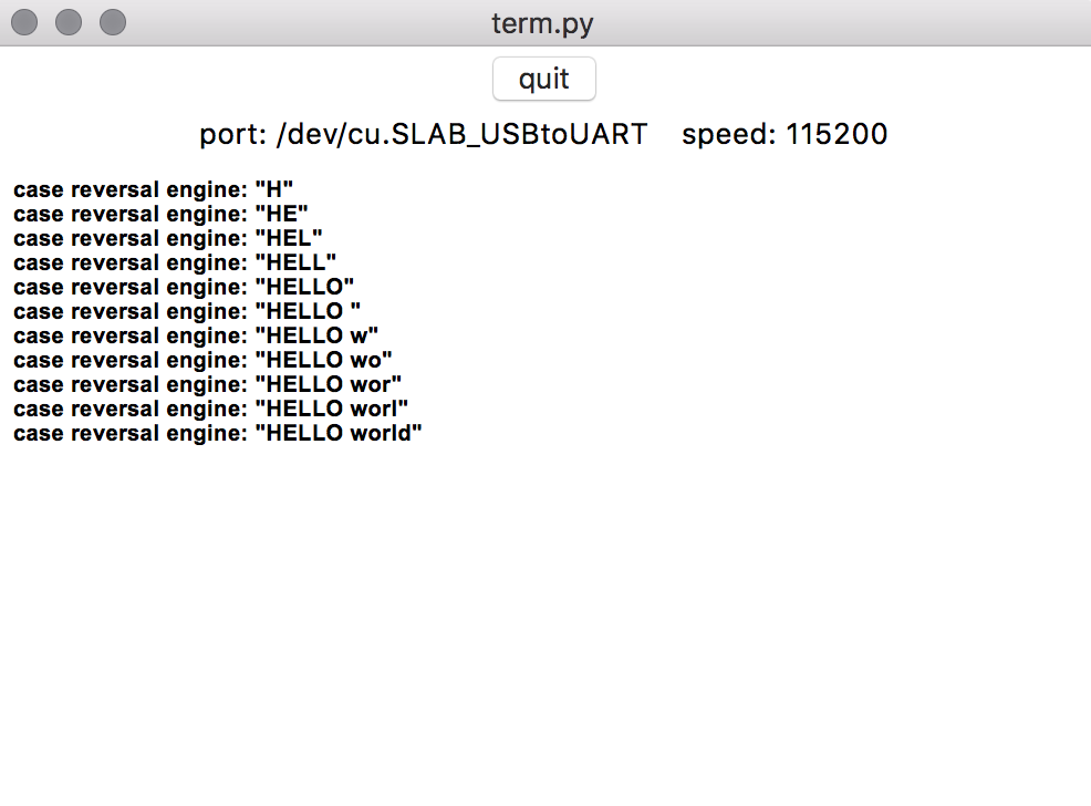 Hello World reverse case result
while (1) {
      get_char(&serial_pins, serial_pin_in, &chr); //this is where it gets the characters from keyboard.
      put_string(&serial_port, serial_pin_out, "case reversal engine: \""); // I changed the string message to the case reversal engine.

      if (chr > 64 && chr < 91){ // I added an if and else if function. For this I used the ASCII table
         chr = chr + 32;
      } else if (chr > 96 && chr < 123){
         chr = chr - 32;
      }

      buffer[index++] = chr; // a buffer is an array with length max buffer. Here it stores the characters I typed.
      if (index == (max_buffer-1)){
         index = 0;
      }
      put_string(&serial_port, serial_pin_out, buffer);
      put_char(&serial_port, serial_pin_out, '\"');
      put_char(&serial_port, serial_pin_out, 10); // first I change
   }
}
Step 6: writing native C with Eclipse
Based on the feedback of the global evaluation I did an extra bit. I used another environment and I used another language: native C instead of the Arduino C.
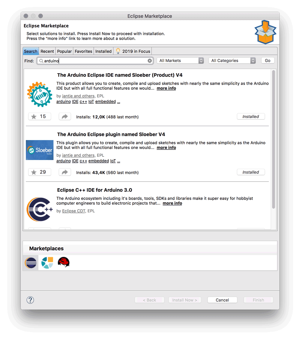 Sloeber IDE plugin for Eclipse IDE
- Download Eclipse and install it.
- It asked for JDK so I also installed the JDK 11 development kit
- In Eclipse I looked for AVRplug-in. The link to the avr library on the Fab Academy site gave me an ip-error. I wasn’t able to download the AVR library and connect into the plug-in.
- Next step was to see if there’s a Arduino connection with Eclipse.
- I found the Sloeber IDE which is an Arduino alternative. I downloaded and installed it.
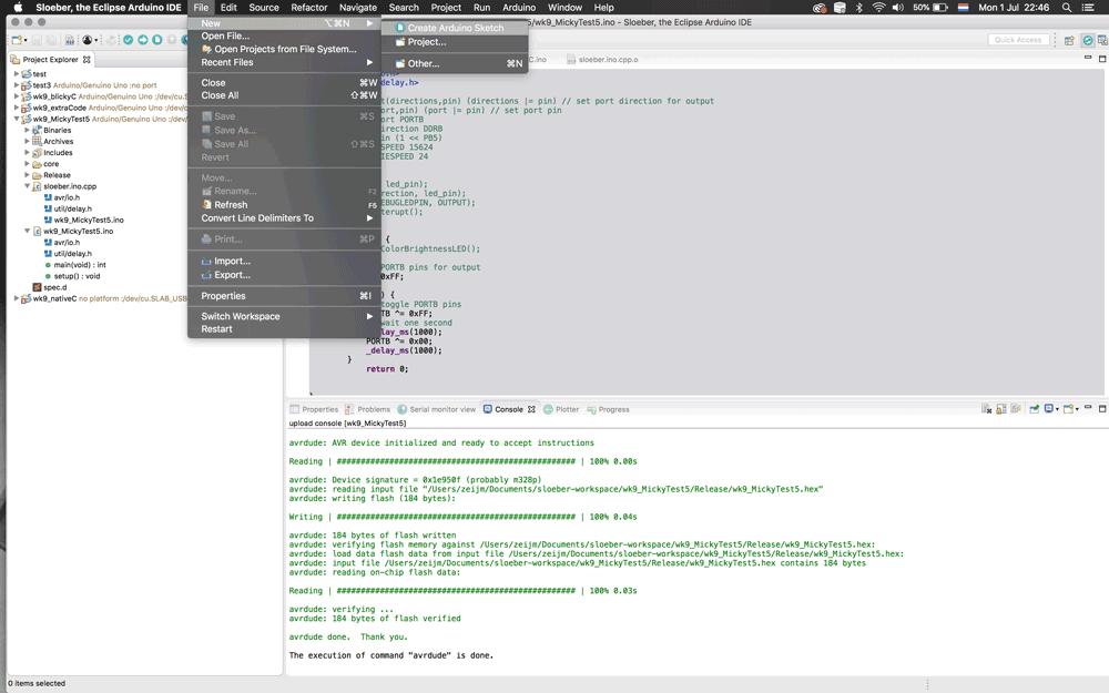
- It works like an Arduino IDE but within Eclipse.
- Click on: create new Arduino Sketch
 Sloeber IDE plug-in for Eclipse IDE
- It gave an pop-up with several options for the board you want to use. I stayed with the default Arduino Uno board because I will use my Satsha Kit of my final project, but you can add the json files of damallis as well.
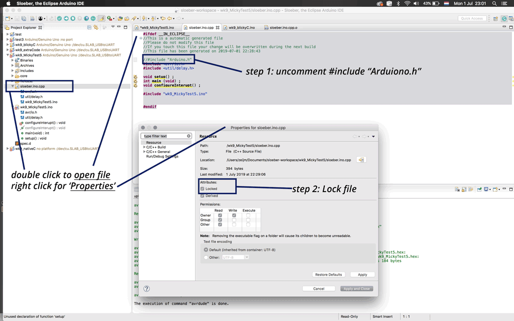
- To make sure I wasn’t working with the Arduino library in the end, I had to do a bit of a ‘hack’ as the Sloeber IDE kept on adding the arduino.h library. On the side in Eclipse you can also find the C++ (cpp) file, double click on it. It shows the following.
#ifdef __IN_ECLIPSE__
//This is a automatic generated file
//Please do not modify this file
//If you touch this file your change will be overwritten during the next build
//This file has been generated on 2019-07-01 22:28:43

//#include "Arduino.h"
#include <avr/io.h>
#include <util/delay.h>

void setup() ;
int main (void) ;
void configureInterupt() ;

#include "wk9_MickyTest5.ino"


#endif
- I commented out the #include “Arduino.h” and locked the file so it wouldn’t overwrite it during the next build. This worked
 Sloeber IDE uncomment “arduino.h”
- I used the C-code of my output week as a start to write a simple LED Blink. I thought this was important to set all the timings.
- I deleted the part for my RGB-charlieplexing and I looked for a simple C-blink example. I found one by Eric Evenchick. I added the blink part.
#include <avr/io.h>
#include <util/delay.h>

#define output(directions,pin) (directions |= pin) // set port direction for output
#define set(port,pin) (port |= pin) // set port pin
#define led_port PORTB
#define led_direction DDRB
#define led_pin (1 << PB5)
#define DEBUGSPEED 15624
#define CHARLIESPEED 24

void setup() {
set(led_port, led_pin);
output(led_direction, led_pin);
	pinMode(DEBUGLEDPIN, OUTPUT);
  configureInterupt();
}

int main (void) {
  //recalculateColorBrightnessLED();

	// set all PORTB pins for output
	    DDRB = 0xFF;

	    for (;;) {
	        // toggle PORTB pins
	        PORTB ^= 0xFF;
	        // wait one second
	        _delay_ms(1000);
	        PORTB ^= 0x00;
	        _delay_ms(1000);
	    }
	        return 0;


}


//Interrupt code
//this will compile for Arduino UNO, Pro and older boards
#if defined(__AVR_ATmega168__) || defined(__AVR_ATmega328P__)

void configureInterupt() {
  //cli();
  //noInterrupts();

  TCCR1A = 0; //set entire TCCR1A register to 0
  TCCR1B = 0; //same

  //set compare match register to desired timer count:
  OCR1A = CHARLIESPEED;
  //int timer1_counter = 34286;
  //TCNT1 = 34286;

  //turn on CTC Mode
  TCCR1B |= (1 << WGM12);
  //TCCR1B = 1<<WGM12 | 7<<CS10;

  //Set CS10 and CS12 bits for 1024 prescaler
  TCCR1B |= (1 << CS10);
  //TCCR1B |= (1 << CS12);

  //enable timer compare interrupt
  TIMSK1 |= (1 << OCIE1A);

  //enable timer overflow interrupt
  //TIMSK1 |= (1 << TOIE1);

  //interrupts();
  //sei(); //enable global interrupts

  //digitalWrite(DEBUGLEDPIN, HIGH);
}

//for ATTiny85
#elif defined(__AVR_ATtiny85__)

void configureInterupt() {
  // Set up Timer/Counter1 to multiplex the display

  TCCR1 = 1<<CTC1 | 7<<CS10;    // CTC mode; divide by 64
  OCR1C = CHARLIESPEED;         // Divide by 25 -> 5kHz
  TIMSK = TIMSK | 1<<OCIE1A;    // Enable compare interrupt
}

#endif


//Timer/Counter1 interrupt - multiplexes display

//this will compile for Arduino UNO, Pro and older boards
//#if defined(__AVR_ATmega168__) || defined(__AVR_ATmega328P__)
//ISR (TIMER1_COMPA_vect) {
//for ATTiny85
//#elif defined(__AVR_ATtiny85__)
//ISR(TIM1_COMPA_vect) {
//#endif

  //displayNextLEDRow();
//}
- This worked but seemed really complex to me, so by uncommenting parts I looked if I could simplify it as much as the example given.
- Finally I was able to delete everything around it and stayed with a simple blink code from the example code.
Based on the example given by Eric Evenchick

#ifdef __IN_ECLIPSE__
#include <avr/io.h>
#include <util/delay.h>

void setup() {
}

int main (void) {

	// set all PORTB pins for output
	    DDRB = 0xFF;

	    for (;;) {
	        // toggle PORTB pins
	        PORTB ^= 0xFF;
	        // wait one second
	        _delay_ms(100);

	    }
	        return 0;
}

#endif
- One important part to make sure I was still not working with the Arduino libraries. I first uncommented the code in the Arduino-file (ino) and copied the code to the CPP-file.
- When this was working, I deleted the ino file from the folder to make sure I only had the CPP-file. Now I have a cleaned up version.
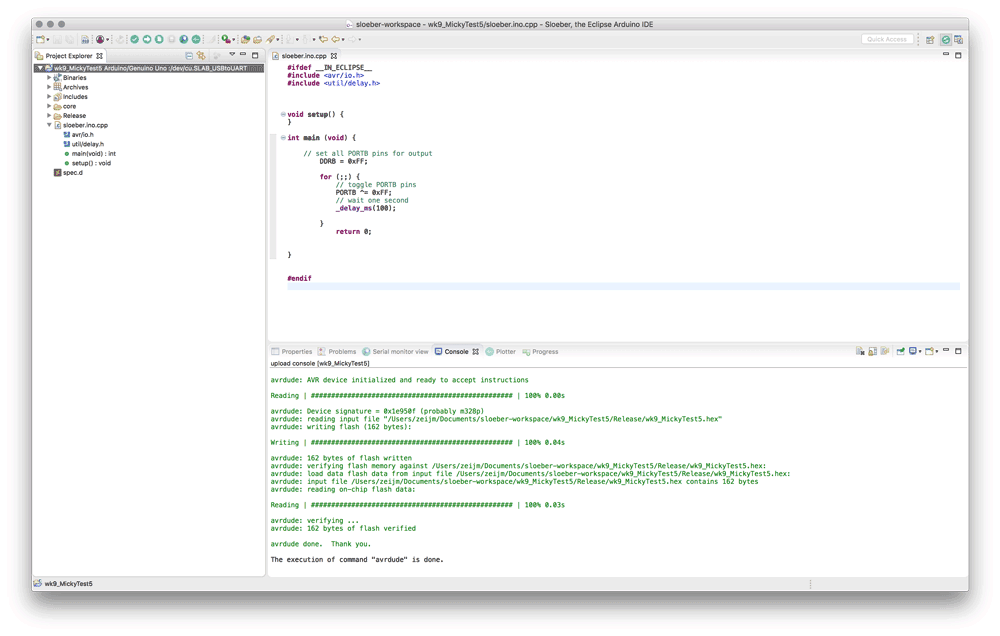 Sloeber IDE with CPP-file
It’s a bit of a work around, but this was the best solution for the time I had. I tried making a C/C++ file in Eclipse but somehow I wasn’t able to build it. This took me too long to figure out, therefore I used the Sloeber IDE. This way I still had some familiar interface items from the Arduino IDE and I could build and upload my code to my board and I did a simple C program.
Blink code
What I did wrong – and how I solved it
Setting the ports with Neils file
When I first used the make files by Neil to see if it would work on my board as well, I had some problems. The last command didn’t work for me. First I thought I had to install python to make it work. However I use macOS which already includes python. I still installed PIP to be sure. However it still didn’t work. Until I realized I set the port wrong. For my mac it should be /dev/cu.SLAB_USBtoUART when I used this it worked.
Term.py doesn’t recognize all control character in ASCI
When I changed the file by Neil, some of the changes did’t pass through because the Phython term.py didn’t regonize the control characters. I changed 10 (new line) to 13 (return) this didn’t work. As well as adding a beep with decimal ascii code 7 (bell)
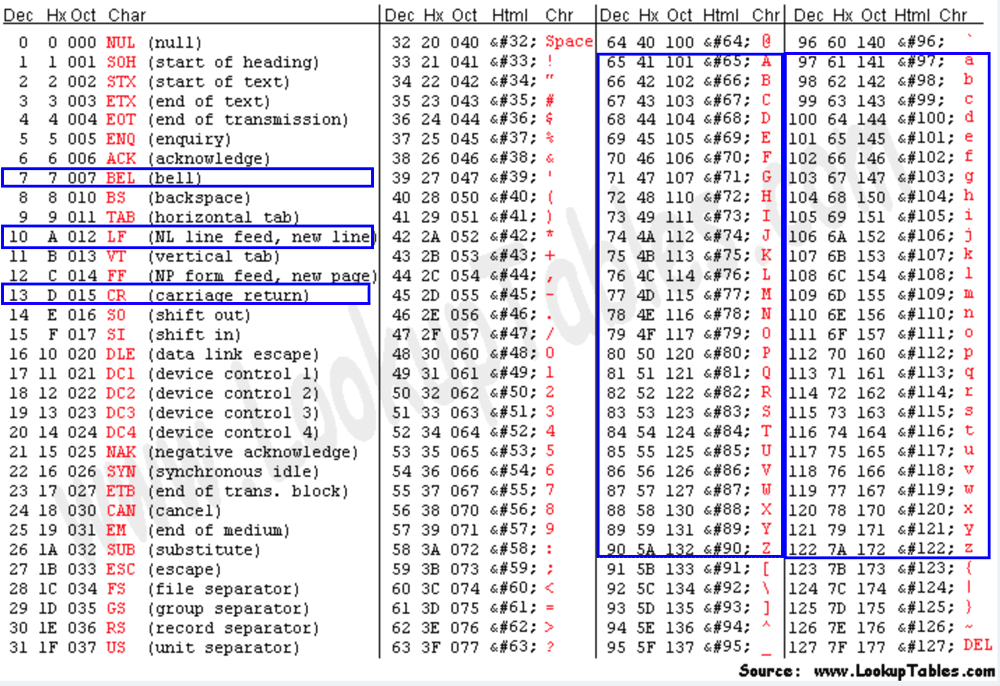 Ascii table with control characters
Klaas-jan helped me to look into the term.py code to understand what was happening, why it didn’t recognize the control characters. As far I can understand control characters are hard coded into this term.py and provide a limited set.
What I learned
How to plan
This week I kept the assignment easy and simple as Neil often mentions to plan for the time you have. And this week I didn’t have much time. I decided to skip the molding and casting week and move this assignment to the break and to keep this weeks assignment simple. I learned that good planning makes a big difference.
How to read a datasheet
While I was trying to get an understanding of the features listed in the beginning of the datasheet, I realized that the structure of the datasheet is linked to this list. Each chapter provides more information for each feature. This provides a good overview of what’s in the Microcontroller and where to find which information in the datasheet. It’s important to lookup each word or terminology used in the datasheet that I don’t understand as I’m new to electronics. Therefore Wikipedia and tutorials are my friends, it helps me to get an overall understanding of how Micro-controllers work.
How to program in C
Eventhough I only changed and added a bit in Neils codes, it did give me a better understanding of how the program works. In the end this was sort of simular to the Arduino IDE. This gives me more confidence to play around and try our more fun stuff with programming my board.
What made me proud!
Changing the file from Neil made me proud because it gave me more confidence about how to change given code and it showed me that it can be fun to program.
Credits and References
Klaas-jan helped me with explaining the parts of Neils code and where I should add functions and to figure out why the term.py didn’t work with the different control characters.
Image references
- Image Makey Makey
- Image SE555 on magicco.info
- Image Raspberry Pi Zero
- Image ESP8266