12. Output devices
This weeks group assignment is to measure the power consumption of an output device. And the individual assignment of this week is to add an output device to a Microcontroller board I’ve designed, and program it to do something.
Files, planning and tools
Files
- Kicad-files of my board
- Illustrator-file leaf outline board
- Code used as basis by Johnson Davies
- First rewritten version for Arduino Uno of Johnon Davies’ code
- Rewritten code by Klaas-jan Winkel
Planning
This week my focus will be on understanding how to program my board and on my first output spiral for my final project.
- Group assignment and its documentation.
- Visit STRP-festival for inspiration
- Designing my board.
- Experimenting with shape memory alloy.
- Reproducing my board with an Arduino.
- Getting an understanding of the code.
- Making my own board and understanding the code for the Attiny.
Tools
- Mods
- Roland Modela MDX-20
- Arduino Uno
- Arduino IDE
- Breadboard and components
Link with final project
For this week I wanted to experiment with the output possibilities for my final project. At the moment I’m thinking of two possibilities for lighting up the leaves in my tree.
- Use a RGB LED-matrix to light up glass fiber in the leafs.
- Use a RGB LEd-matrix for each individual leaf.
My preference is the first option, I think this will give the most beautiful result. However I think it’s also the most difficult option. Therefore I wanted to start with created my own small RGB LED-matrix.
Research and inspiration
This week I went to the exhibition Here’s to the Future at the STRP-festival in Eindhovenand to Design Nonfiction: Transformations in design practice between the Dotcom Crash and the rise of machine intelligence at MU exhibition center to get more inspiration on output.
 Exhibition at STRP Festival 2019 and MU
In addition I did a lot research this week into several subject matters as I really wanted to get a better understanding of the difference between Multiplexing and Charlieplexing and how Shape Memory Alloy (SMA) works. In the end I also had to researched a lot on bitwise operations, how interrupts and timers work, and how to use the datasheets to find out which registers to use.
Links to shape memory alloy
- High-low tech: Electronic Origami Flapping Crane
- Intro to shape memory alloy actuation using Flexinol
- Science Friday: How to make a memory wire circuit
- Flexinol Leaves
- SMA project: ticklish plant by Jie Qi
- Figueirede Tiago’s Fabacademy page on Shape Memory Alloy
Links related to Multiplexing and Charlieplexing
- Wikipedia page Charlieplexing
- Wikipedia page Multiplexing
- Thomas Feminier’s Fabacademy page on charlieplexing RB Leds
- How to Multiplex an LED Grid
- Multiplexing (for beginners) by EC-Projects
- Charlieplexing LEDs by Stijn Coppens
- How to Charlieplex RGB LEDs by Hammes Hacks
- Driving Four RGB LEDs from an ATtiny85
Links to timer interrups and bitwise operations
- Wikipedia page Bitwise operation
- Operators in C
- Level Up Your Arduino Code: Timer Interrups by SparkFun Electronics
- Timers by AVR-beginners
- Arduino Pinout diagram
- Arduino Timer Interrupts by Hobby Electronics
- Interrupts on Gammon forum
Links to the datasheets and footprints
- Datasheet ATtiny85
- Datasheet ATmega328P -Arduino Uno chip
- Datasheet RGB-LED used
- Symbol library RBG-LED used
- LED Resistor Calculator
What we did – Group assignment step-by-step
This weeks group assignment is to measure the power consumption of an output device. For this week we didn’t use the power supply from week 5 but a small cheaper version in combination with a big power bench. You can use this as well to test the voltage the circuit is using.
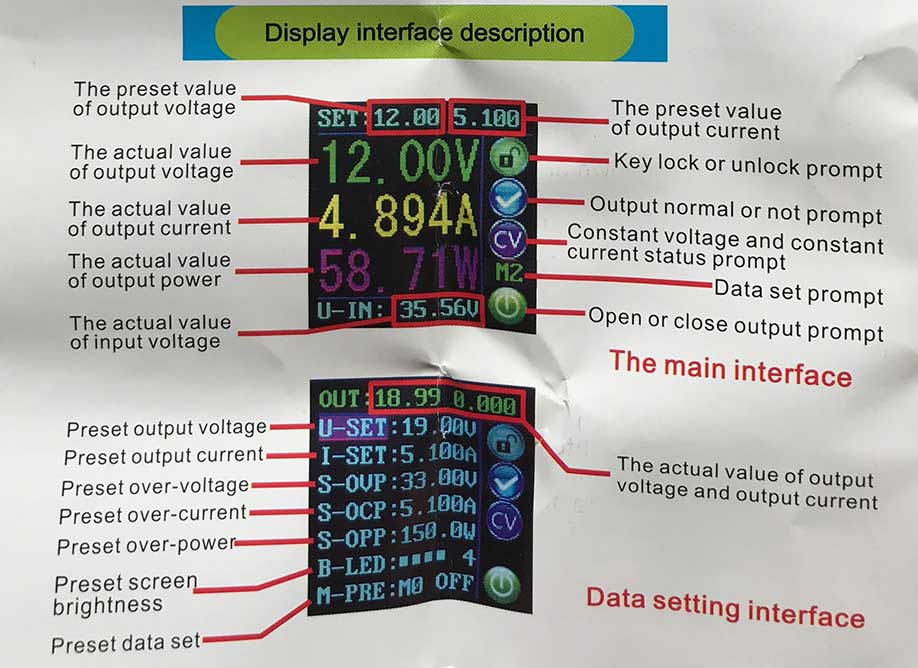 Interface for the power supply
We used Henk’s final project of last year to measure the output. As you can see in the image below it tells you the voltage, current and power the circuit uses.
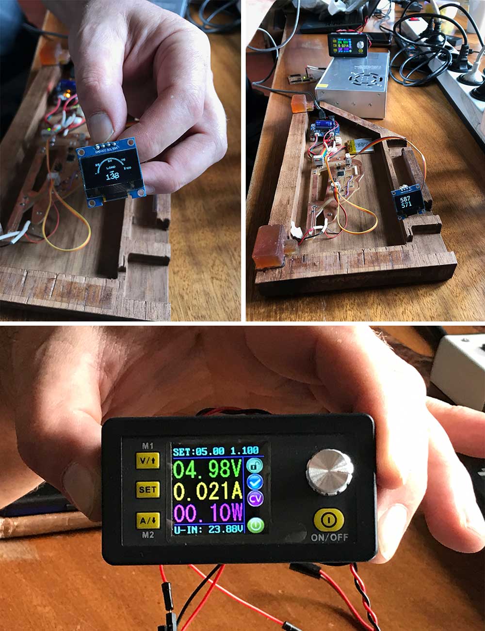 Group assignment measuring consumption of output device
What I did – step-by-step
This week my goal was get a better understanding of the programming part and to create a RGB-LEd matrix. My first steps this week were to reproduce the the example by Johnson Davies with the Arduino so I would be able to test out the programming and change the flow of LEDsmyself before I would mill and solder my own board.
Step 1: Design my board in Kicad
This week I started with designing my board. I wanted to make an RGB matrix because I will use this for my final project. That way this week would be a nice first small spiral. Because I’m new to electronics and programming and looked into some examples. However there weren’t many about RGB-matrix, most of them were about LED-cubes or they used a prefab RGB matrix. I found a nice project by Johnson Davies on technoblogy. So I used his schematics and matrix as basic start and added the capacitor, an 10k resistor, a power converter and the headers myself.
Charlieplexing matrix RGB-LED linked to ATtiny85 pins
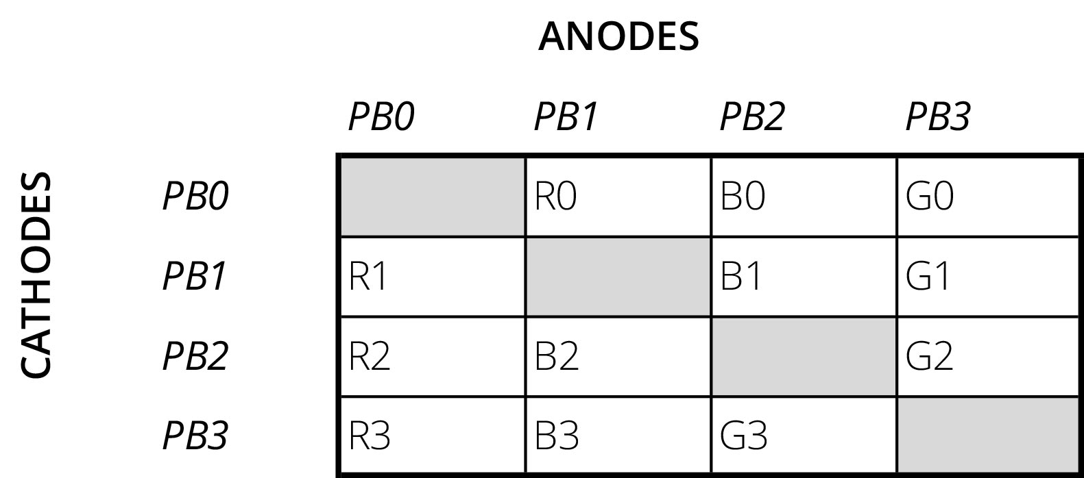 Matrix RGB-LED related to the pins of ATtiny85
Schematics of my board
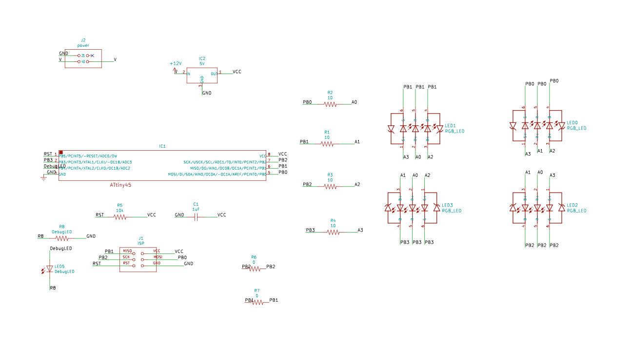 Schematics of my RGB-LED board
- I used the LED Resistor Calculator in combination with the datasheet of the OVSPRGBCR4 RGB LED to calculate which resistors I should use. It said it should be 10 Ohm.
- I added the 5V power converter and the 2x2-header because I saw this in each of Neil’s examples.
- I added the 1uF capacitor and the 10k resistor as we add these to the Attiny.
- I added the ISP-header to be able to program my board.
- List of components used for my board:
- ATtiny85
- 1uF Capacitor
- 10k resistor
- 5V power converter
- ISP-header
- 2x2-header
- 4 x an 10 Ohm resistor
- 4 x an RGB LED (OVSPRGBCR4)
- 2x zero Ohm resistor
Routing of my board
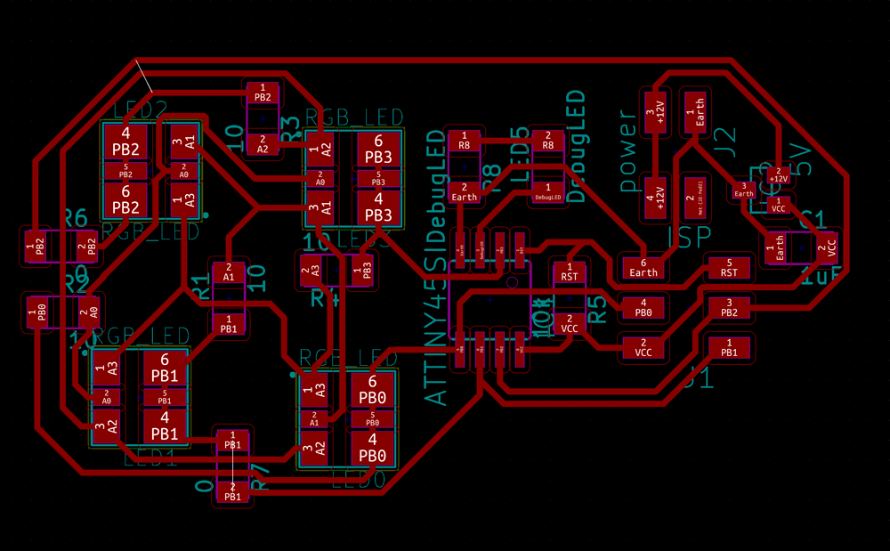 Routing and design of my RGB-LED board
The routing of a board is really addictive to me, I again set the goal to use as little zero Ohms as possible. However I needed 2 in the end which is logical as I’m using Charlieplexing. For the outline I created an leaf-shape in illustrator.
Step 2: Reproduce the board with a breadboard and Arduino
Before I would mill this board (I reserved the machine on Monday afternoon) I wanted to test out how the schematics would work and I wanted to figure out how I could change the given code.
- Use a breadboard and plug-in all the component.
- I used pins of the Arduino in stead of the ATtiny
- I didn’t add the capacitor and the 10k resistor as these are linked to the ATtiny
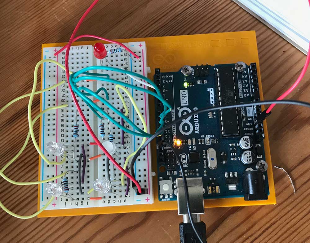 Arduino prototype of my RGB-LED board
Step 3: Rewrite the code for Arduino
Reproducing the schematics on a breadboard was the easy part. When I wanted to compile the the code by Johnson Davies and use it for my prototype the Arduino IDE said that it wasn’t able to compile for the Arduino Uno. So I took the following steps.
- First I researched what could be the problem. I realized the Arduino uses different registers for the clock and interrupts. You can find useful links above.
- I used the datasheet of the Arduino Uno, which uses a ATmega 328P, and the datasheet ATtiny85 and ctrl+F to find the relating registers. This is what should change.
- TCCR1 should be TCCR1A and TCCR1B
- CTC1 is WGM12
- OCR1C is OCR1A
- TIMSK is TIMSK1
- OCIE1A isn’t an overflow as written down by Davies but an compare
- Start with setting the TCCR registers to zero otherwise it interferes with the Arduino settings.
- start with noInterrupts(); and setup with interrupts();
- TIM1 = TIMER1
//Setup for the ATtiny as used by Johnson Davies
TCCR1 = 1<<CTC1 | 7<<CS10;    // CTC mode; divide by 64
OCR1C = 24;                   // Divide by 25 -> 78Hz
TIMSK = TIMSK | 1<<OCIE1A;    // Enable overflow interrupt

// Timer/Counter1 interrupt - multiplexes display
ISR(TIM1_COMPA_vect) {
}


//Setup needed for the Arduino Uno/ATmega328P
noInterrupts();

TCCR1A = 0; //set entire TCCR1A register to 0
TCCR1B = 0; //same

//set compare match register to desired timer count:
OCR1A = 24;
//int timer1_counter = 34286;
//TCNT1 = 34286;

//turn on CTC Mode
TCCR1B |= (1 << WGM12);

//Set CS10 and CS12 bits for 1024 prescaler
TCCR1B |= (1 << CS10);

//enable timer compare interrupt
TIMSK1 |= (1 << OCIE1A);

//enable timer overflow interrupt
//TIMSK1 |= (1 << TOIE1);

interrupts();

}

// Timer/Counter1 interrupt - multiplexes display
ISR (TIMER1_COMPA_vect) {
}
In the end it was a lot more difficult to find the right way to change the registers. As I quickly found the right registers however it still wouldn’t work. I asked my boyfriend Klaas-jan to help me. And we looked at it and researched a lot. In the end we had to set everything to zero for the Arduino and we made a small typo. But we managed in the end to get to work on the Arduino.
Arduino prototype working
Step 4: Milling and soldering my board
Milling my board
With the Milling I had some trouble with the outline traces. First because I had to refresh mods. I realize it but it cutted the outline in one go breaking the mill. So I had to restart Mods, change the mill, and make sure it cut through in four steps. I made a leaf shape and the petiole was too thin to mill so I lost it.
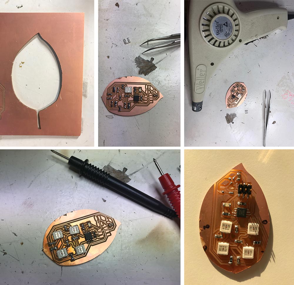 Soldering my board with a heat gun
Soldering my board
The soldering went fine till I realized that the RGB-lEDs can only be soldered using a heat gun or over. It was the first time for me to solder this way. The steps I took:
- Add solder to the footprint of the RGB-LED on my board.
- Add solder to the RGB-LED where it should connect.
- Place the LED on top of its footprint, hold it with a tweezer
- Hold the heat gun above it while keeping the LED in place
- Wait till solder melts.
- Remove heat gun make sure to keep LED in place till it cools down.
- Make sure the LED is stuck to the board.
- Double check the connections with the multimeter.
Step 5: Debugging my board
When I wanted to program my board, I first checked with the avrdude command if it could recognize it. It did but while I was doing this I smelled something familiar which reminded me of the heat gun. It turned out my board was heating up, so I removed it from the USB-hub. Before I could program it, I realized that I had to debug what was wrong.
- First step was to find out which component was the problem. I recreate the mistake by plugging it back in and quickly checking each component by touching it to find out which one was heating up.
- I did this really short and found the problem straight away the capacitor was heating up really quick that I wasn’t able to touch it.
- I used the multimeter to check if the capacitor was still working. When you set the Ohm high you can see the movement in the capacitor. And when you set it on Volt it shows how voltage flows back. I used the tutorial by ifixit on how to use the multimeter to troubleshoot the capacitor.
- To get a better measurement I de-soldered it from my board, In addition I de-soldered a capacitor from the test board I made last week as I knew that one worked. This way I could compare the both.
- It turned out that the capacitor that was on my output board didn’t work. So I though this must be the problem.
- I soldered the other capacitor on my board hoping this would solve the problem.
- I plugged my board with the new capacitor in my USB-hub, but it again heated up. So that would mean something else was the problem.
- The first thing I thought of was the power regulator in combination with the 2x2-header. As I added these not knowing why and they are linked to power. However I first thought this wouldn’t be a problem because there’s no power source connected.
- I removed the power regulator and the 2x2-header from my board.
- I plugged in my board and it worked! Nothing was heating up anymore and I could program it.
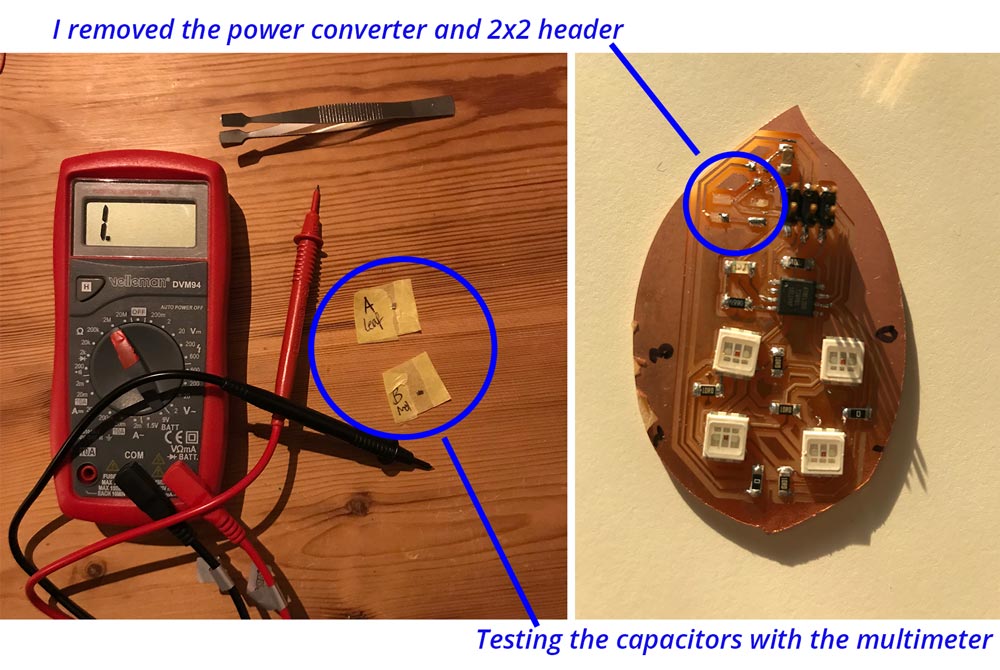 Debugging my board: comparing the capacitors and removing the power regulator
Step 6: Programming my board.
After I troubleshooted my board I could program it. I first bootloaded my board. Johnson Davies uses a board manager for the ATtinys. I researched it and this version by Drazzy gives more options to set the clock speed.
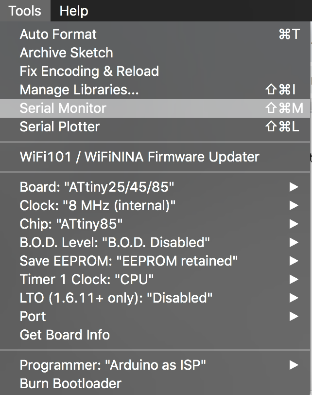 Setup bootloader ATtiny85
After I burned the bootloader I uploaded the rewritten program by Klaas-jan, I couldn’t stop him as he found it too much fun and interesting to rewrite it in such a way I could understand it, and the program worked straight away as you can see in the video below.
My own RGB Led matrix board working
What I did wrong – and how I solved it
The main problems of this week were related to me not knowing enough to realize how difficult things are.
There’s a difference in shape memory alloys.
Our Fablab didn’t have any shape memory alloy in stock therefore I ordered it myself. However I couldn’t find Flexinol in the Netherlands therefore I ordered Nitrinol. As I thought it was a brand difference. But when I did the experiments from my research linked above nothing worked the way it was described. I could shape the material with heating it, however I wasn’t able to reshape it and let it move back to it’s remembered shape. Till I realized I had a different material. I order the real deal from Robotshop, so next week I can do my experiments.
There’s a difference is settings for the ATtiny85 and Arduino
Before I started this week I didn’t realize there’s a difference in registers for the ATtiny85 and the Arduino Uno. I saw the example by Johnson Davies and thought it would not be a big hassle to prototype it with the Arduino because they’re both from the AT-family. This turned out not to be the case. The good thing is that in the end I learned a lot about how to use the registers in the datasheet.
My board was heating up.
As mentioned above, when I plugged in my board to program it the board heated up. In step 5, I describe step-by-step how I solved this problem. In the end it turned out to be the power regulator.
What I learned
This week I learned a lot mainly from my own mistakes and Klaas-jan gave me a lesson in bitwise operations.
How to prototype with a breadboard and Arduino
My idea for this week was to make a quick prototype with Arduino and a breadboard so I could play around with the code. This turned out to be much more difficult than I thought. Before I could play around I had to research a lot about how to change the registers. In the end I could get it working and the good thing is that it’s all set up now so I can prototype in the coming weeks with adding LEDs to the circuit.
How to use Charlieplexing and Multiplexing.
Before I could design my board I first had to get a better understanding of the difference between multiplexing and Charlieplexing for this weeks assignment. My goal was to Charlieplex a RGB-LED matrix, but some said that it would be too complex. While I thought it would be the same as three separate LEDs so that in the end that wouldn’t be a big difference.
Multiplexing vs Chalieplexing
- Multiplexing uses a matrix and turning the pins ON and OFF (or HIGH and LOW)
- Charlieplexing uses the tristate principle. In addition to ON and OFF it switches the OUTPUT state to INPUT. This way you can use three states and therefore use even less pins.
Matrix RGB-LED related to the pins of ATtiny85
This Poster explaining the difference between Multiplexing vs Charlieplexing.  Multiplexing vs Charlieplexing poster by fringeneering
Charlieplexing does make the programming more difficult with the RGB-LEDs. I still didn’t totally get how Johnson Davies wired up his matrix in the code. My goal for next week is to fine tune the code and make changes in the order it flows through the LEDs.
How to debug my board.
This week I learned again more about how to debug the electronics. Most important is to be able to compare different parts and to double check it with different boards and similar components. What I learned most is to make sure that before you start to know why you put something on the board.
How to use bitwise operations
The example code I used this week for my RGB-LED matrix made use of bitwise operations. As I’m very new to programming I had to get a better understanding of it. Klaas-jan explained me how it works and how you can calculate the bit changes yourself with pen and paper. What it does is that it changes the bits linked to the brightness and position of the LED.
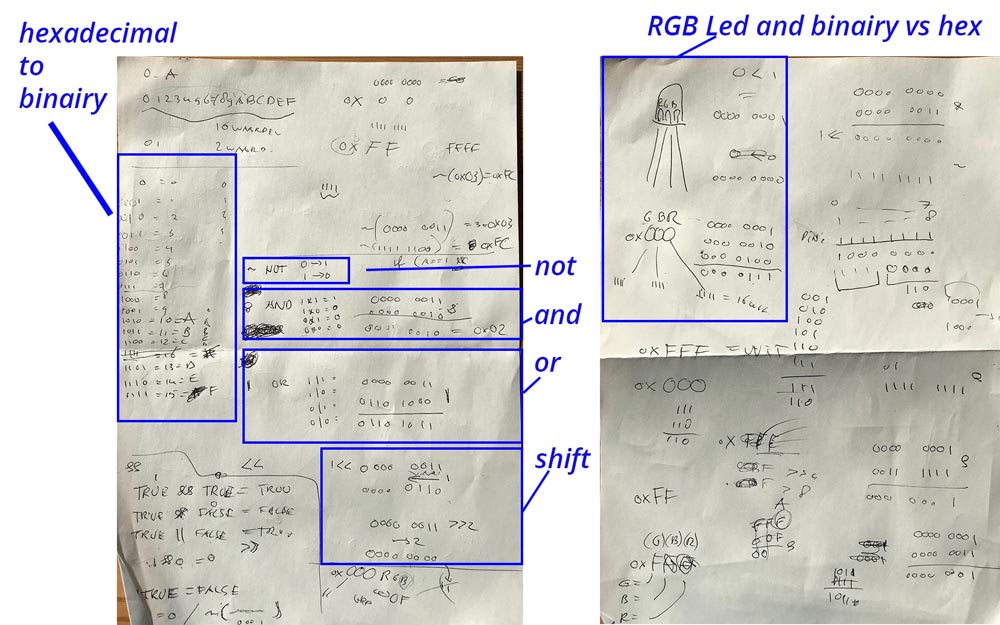 Programming lesson by Klaas-jan
The code by Johnson Davies uses hexadecimals in stead of binary. So first I had to figure out how this works. And how they are related. The hex-codes reminded me of illustrator and using color. It’s fun transfer these to binary and to calculate the bits with NOT, AND, OR, SHIFT. These are in a way very small functions as you can see they change the bits.
Why use bitwise operations?
It seems more difficult to use bitwise operations to program my board. But since programming is all knew to me, I wanted to see if I could get a hang of it. The reason why it is good to understand bitwise operations is that it uses less memory on the chip and it’s quicker than logical programming this makes the program a lot faster. Which is again useful when using Charlieplexing because the idea of Charlieplexing is that is flickers so fast your eye can’t see it. The faster it the chip can process the code the nicer the end result will look. I can use this for my project because my end goal is to have a bigger RGB-LED matrix.
What made me proud!
This week made me really proud because I managed to create my small RGB-LED matrix. I’m especially proud because this week I start to understand the electronics a bit more and I’m slowing getting a hang of understanding the programming behind it.
Credits and references
Klaas-jan helped me this week with rewriting the code by Johnson Davies and he helped me understanding how the code works.