Computer controlled cutting
Goal this week is to cut some things using the lasercutter and vinyl cutter. Together with Heidi. I set on a quest to find the kerf of our laser. The rest of the week I worked on making something on the vinyl cutter and lasercutter.
I started on the vinyl cutter, a machine that I am already familiar with. When Emma saw me making some lame t-shirt stickers so she challenged me to make something
that can move - and Cecilia challenged me to make something that can change color. So I accepted the challenge.
Also I made a press fit kit on the lasercutter.
The lasercutter
The lasercutter is such a fun machine, the cutting is great to look at, it gives quick results and it is easy to learn. Because this machine is so easy going it can easily be forgoten that it is a dangerous machine. Reasons why it's dangerous: 1) It uses a powerfull laser that cuts through (most) materials, 2) The machine doesn't stop by itself if there is a issue (think broken parts, fire, toxic materials).
So the basic rules that go with this machine are as follows:
- Do not leave the machine unattended.
- Only cut materials that you know are safe (no materials that contain chloride, chromium 6 or other irritants).
- Always use the filter and wait for the smoke & smell to be gone before opening the lid.
- Make sure to know what to do in case of fire.
- help eachother
Tools used for lasercutting
Hardware
USB drive
BRM Lasercutter 1612 - CO2 100W - workarea 1200x1600 mm
Roland GS24 vinyl cutter - (55 degrees blade)
Software
Lasercut 5.3
Illustrator
Materials
Corrugated cardboard 3mm

Operation & settings
The laser tube can be found hidden somewhere in the machine, often in the back behind a closed door. The lasertube is a large glass tube that is filled with CO2 gass and has a water cooling system inside. If you run electricity through the tube a invisible light beam comes out of one end and hits into a small mirror that sends it to the next mirror that is moving on the Y-axis and on to a thirth mirror on the X-axis. The last mirror also bends the beam vertically into a lense. The lense converges the beam onto the material. Very similar to making a fire using a magnifiyingglass.
The lasercutter might be one of the most loved tools in the lab because it's so effective at making cool stuff in a super easy way. It only understands two file formats, bitmap and vectors and the most important settings are speed and power. So when you have your material, design and settings you have everything you need to make something cool.
The best settings are the fastest settings giving you a good result. It's different for each material and machine. Most labs offer a list of recommended settings. Speed is set in (roughly) milimeters per second (0 - 400) and power in a (relative) percentage (0% to 100%). In your design you can give different parts different colors. Each color represents different settings.
There are also different ways of cutting. There is cutting, light cutting, engraving and dot. Cutting is the most simple one, this is where the laserbeam cuts all the way through the material. Light cut is where we don't want the material to be cut but just for the laser to mark where the line is. This is very similar to engraving but much faster. Engraving can be done with both vector and bitmap files - the machine engraves between two lines to fill up the design or it switches the power on and off depending on the colors of the bits. Dot is not used that often, but this is when the laser creates a dotted line good for folding.
Step by step guide
- Make your design ready for the lasercutter. Outline text, make everything true to scale, rotate, duplicate, give colors, do all the things you can do before hand.
- Export your design for the lasercutter and put it on a USB drive. For Lasercut 5.3 it's recommended to use .DXF files or .BMP (2 bit) files.
- On the computer next to the lasercutter open Lasercut 5.3.
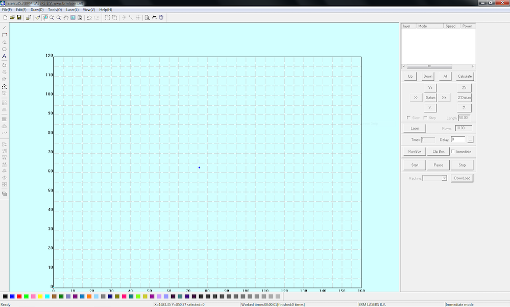
- Draw or copy a small test to figure out your settings. Start with the recommended settings.
- Switch on the lasercutter and wait for it to finish the start up procedure.
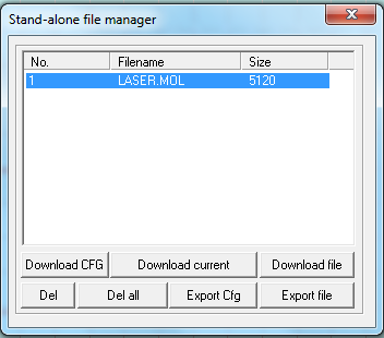
- Send your design to the laser Download > Delete all > Download current. This removes the old file and replaces it with the current file.
- Put your material in the lasercutter and make sure it is as flat as possible. Move the laser above the material and set the focus. Press Anchor to tell the machine this is where you want it to start. Press Test - the machine will now show you where it want's to start.
- Switch on the laser (key 1), press button 2 and turn switch 3 and extraction (switch underneath the computer).
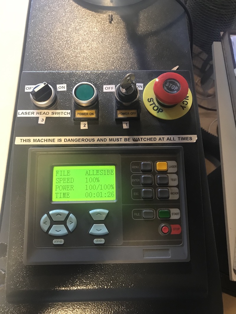
- Press Start. Press start again to Pause or press the emergency button for a quick total stop.
- When the machine is finished it gives a small beep. Wait a for a minute or two before opening the lid and switching of the laser & extraction.
- Check if your settings are as desired. Do more tests until it's perfect, this can take a couple of tries but it will be worth it.
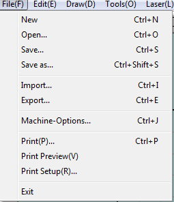
- Import your file File > Import.
- Check if the scale is correct (the small squares in the grid are 50mmx50mm).
- Add your settings and decide the order of cutting. Repeat steps 5 to 9.
- When you are done, switch of the machine and leave everything tidy (or tidier than you found it).
Best practices and common mistakes
- Make sure that the shape you use for testing is represatative for your design. Squares cut differntly than circles. Change your settings and test until you have the perfect settings.
- My lines are not cutting - If you have double lines the lasercutter gets utterly confused, go to Tools in the menu and preform a check, select everything and let the software fix it for you.
- Text doesn't export - make sure to outline text in Illustrator (right click - outline text).
- It's not cutting through - change the speed, go slower OR add some power.
- The cutting line is wide or unfocused - this could mean different things, are you using good settings that should work? If so the focus might be off. Check the distance between the laser head and material. If not there might be an issue with one of the mirrors or lense.
- Corners are burned - lower the corner power. Lasers slow down when changing direction so you need less power.
- Green or brown smoke - you are possibly cutting toxic materials, stop cutting and open some windows. Check your material.
- No laser - did you switch it on?
- Material is not flat - prevent this by storing your material horizontally. Turn it upside down to see if it helps or add some tape or weights during cutting (be very carefull not to bump into them). Don't cut everything in one go - materials with tension will disform during cutting.
- I am using the right settings but my cuts need a lot of cleaning. Some material leave some burn marks on the top and bottom. Mask the materials with masking tape before cutting or wash and sand them afterwards depending on the material. This can also be improved with some extra extraction. It's best practice to start with engraving and ending with cutting.
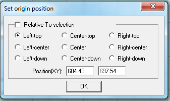
- Change the origin to something that works for you, your design and material.
Laser kerf
When cutting things on the lasercutter it doesn't take into account the material being removed. Although in most cases this is not a issue it can be pretty annoying when you are making thinks that should perfectly fit. The slit made by the laser is called the kerf and it changes slightly depending on the machine, material and settings (but also hummidity, focus, age of the lasertube, place on the bed, etc.). So if you want to perfectly make something to fit you need to make a test - measure - and adjust to compensate for the kerf. The kerf should be around .2mm but it can easily be tested.
Settings
| power | speed | |
|---|---|---|
| acrylic | 60 % | 100 mm/s |
| cardboard | 30 % | 100 mm/s |

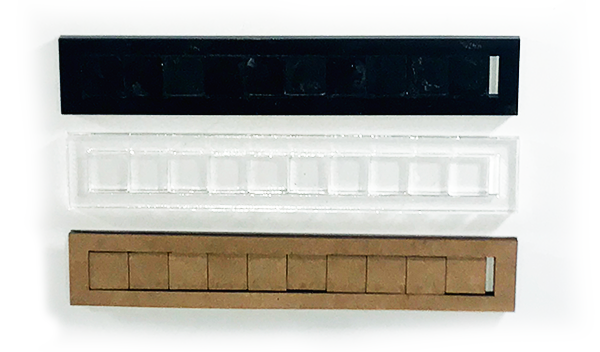
Our goal for the test was to make a special ruler that can quickly give you a indication of the kerf. By sliding a fixed object and seeing where it gets stuck on the ruler it should be possible to tell the kerf. Once you have a perfect ruler you can use it for different materials. But first we had to figure out the kerf for the material we wanted to make the ruler of (Black acrylic - 4mm). And... we also tried cardboard.
The first thing we cut was a simple squares (10x10mm) from both materials. This table was made with a markdown tables generator.
| intended | actual | |
|---|---|---|
| acrylic | 10 mm | 9.64 |
| cardboard | 10 mm | 9.55 |
As you can see the square is not the size we actually intended. The kerf material removed from the acrylic is .36 mm - this is the kerf. To compensate for this we need to offset the square towards the outside by .18 mm (.36 mm/2).
To get a better average we quickly moved on to a better design that was more easy to measure. 10 small squares of 10 by 10 mm. I quickly drew this in Illustrator and made sure not to draw any overlapping lines.
By cutting them in a little frame the squares can be moved to one side and the space left behind (red) can be measured and used to calculate the kerf.


Test results
| intended | actual | difference | kerf (difference/11) | offset (kerf/2) | |
|---|---|---|---|---|---|
| acrylic black | 100 mm | 98.02 mm | 1.98 mm | 0.18 mm | + 0.09 mm |
| acrylic transparent | 100 mm | 97.58 mm | 2.42 mm | 0.22 mm | + 0.11 mm |
| cardboard | 100 mm | 96.55 mm | 3.45 mm | 0.31 mm | + 0.155 mm |
Used materials
Acrylic black - 2.39mm
Acrylic transparent - 2.76mm
Cardboard - 3.74mm
At this point we realised a flaw in our design - the squares we cut out can be turned when put together again. Rectangles would have been better. After checking with the results from other students we realised that the difference was negligible. So we decided not to redo our test.
BexHox
Challenge: design, lasercut and document a parametric press-fit contruction kit. I have a lot of old cardboard from a previous project - so for this project I wanted to do something that had some size to it but also functionallity. My first thought was making something furniture like and I got really inspired by Bloxes. The next day I decided to make a system for storage or showcasing - 'boxes' that can be stacked together, stand alone or wall mounted. The perfect shape... hexagons.
I started with a quick sketch on paper to figure out what parameters I wanted to customise. This wasn't a complete list yet but it gave me a good starting point.
- Material
- Depth of the box, panel height.
- Width of sides.
- Radius of the hexagon.
- Space between hexagons.
- Tab width.
- Tab height.
Next on I started with a small test (a basic part) to see how difficult it was to draw this way in Fusion360 but also to test my workflow for the lasercutter. A square with a negative space for the spacer to fit in and two spacers.
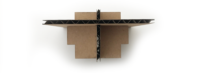
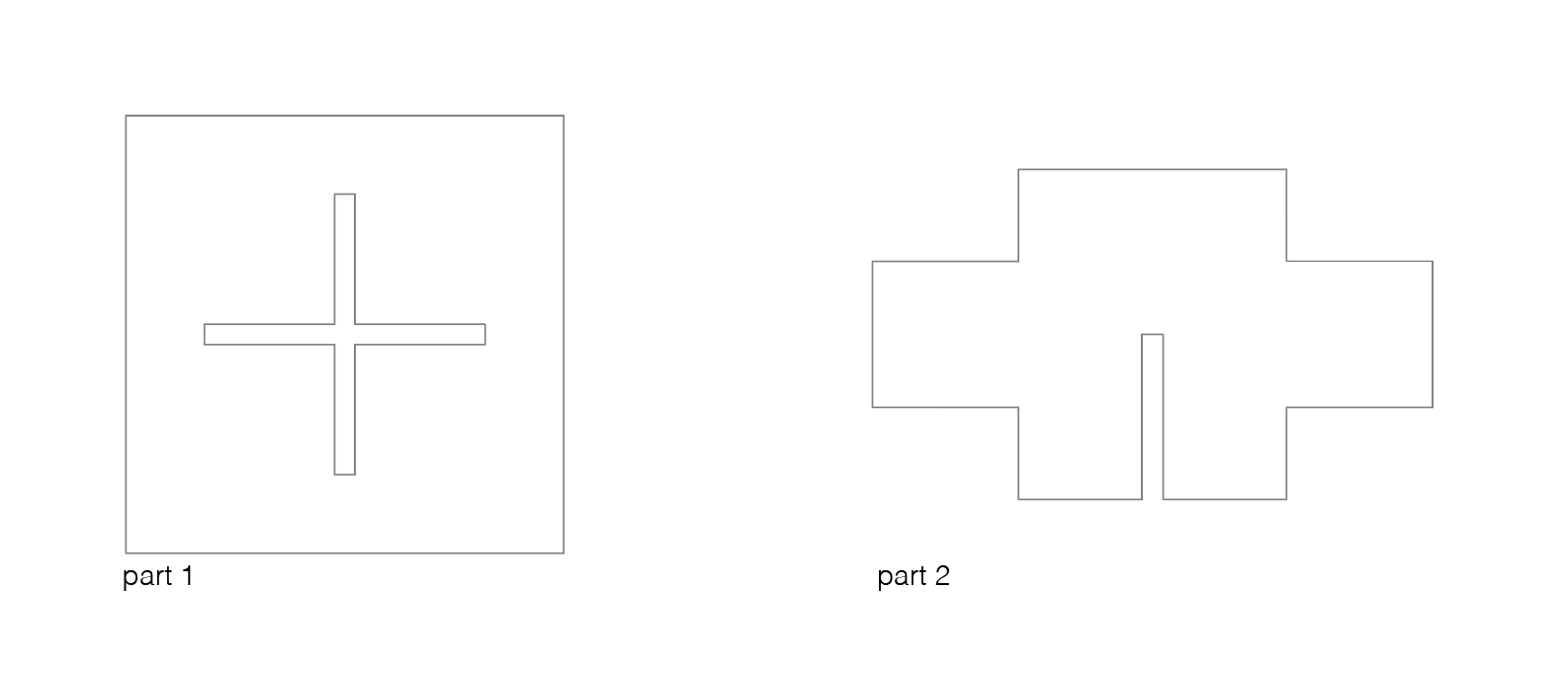
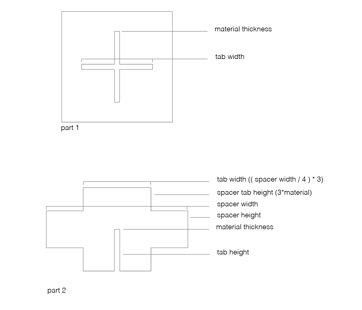
My simple test part turned out to be based on quite a few parameters. This part is probably the most complicated part. I drew everything true to size and added a final parameter to my list: kerf. By selecting everything and giving it an offset of 'kerf/2' towards the outside the design is now ready to cut. I used the kerf settings that me and Heidi calculated and it worked perfectly. There was only one big flaw in my workflow - Fusion exported all lines (including construction lines). In the lasercutter software I manually removed them.
After this I started to draw my other parts improved my workflow. Two things improved my workflow and made them more efficient. The first was not to use the kerf in Fusion but instead do this in Lasercut 5.3 (Tools > Offset polygons). The improvement was to get rid of all the construction lines.

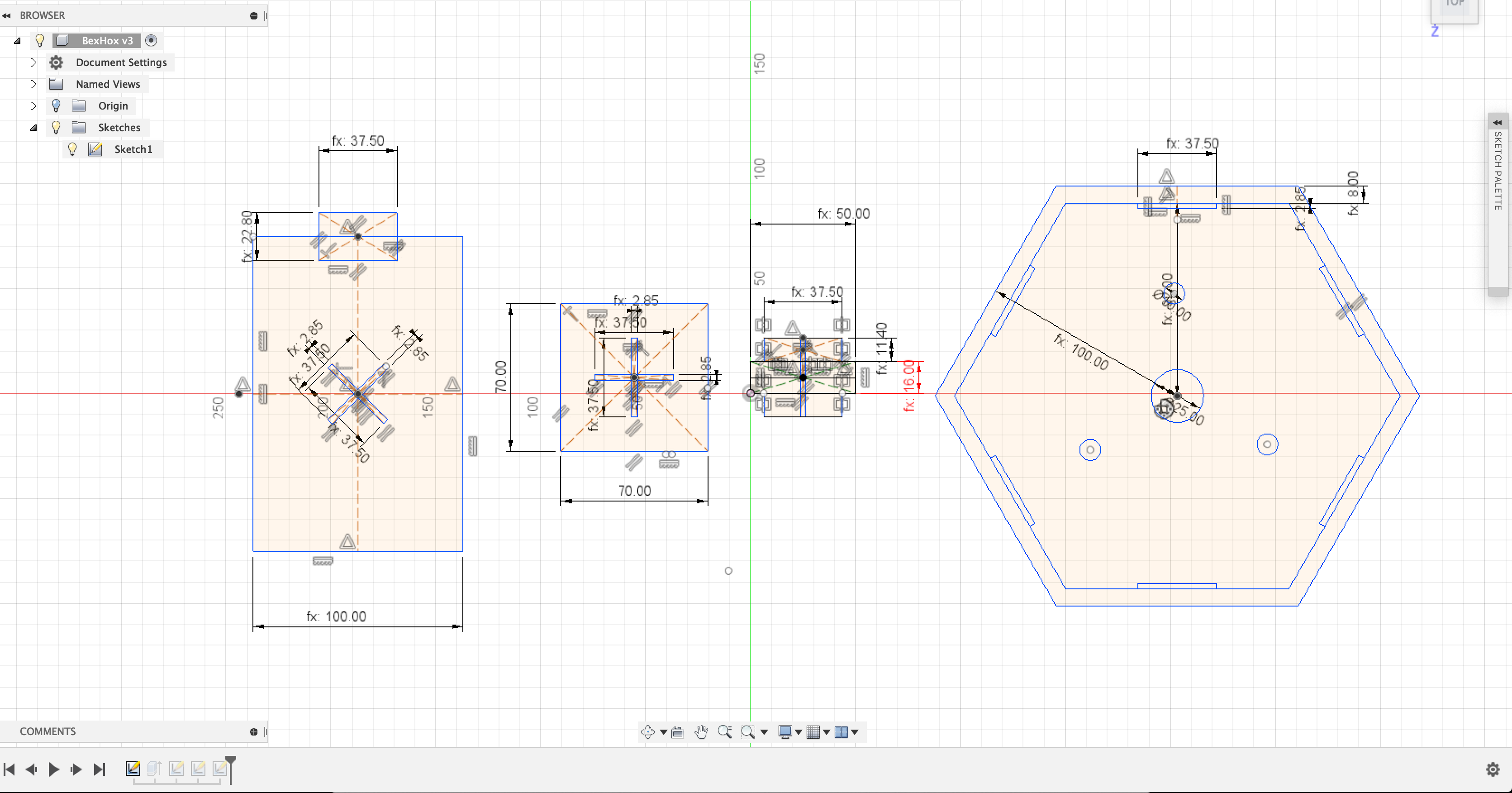
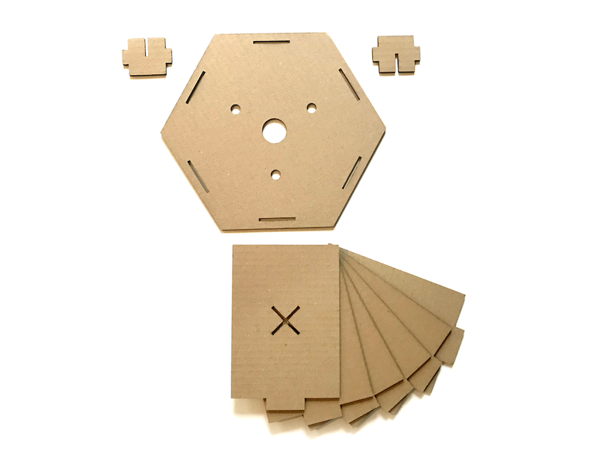
From left to right you see the panels (width and height can be changed - tabs change depending on material thickness), the test square, a spacer tab (spacing height and width can be changed - slot and tabs change depending on material thickness) and the hexagon back (radius can be changed and the slots change depending on the tab settings and material thickness). Ideally the panels are made out of a single piece of cardboard but unfortunalty I ran out of time to figure out how to create a good workflow for creating folding lines within Fusion.

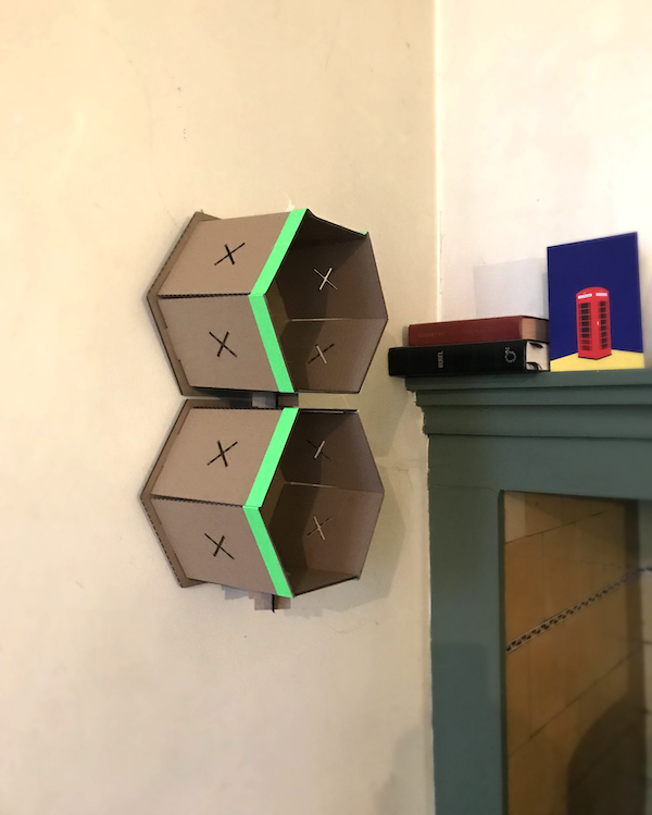
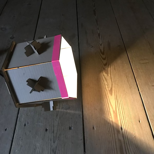
The kit can be assembled in different ways, boxes can be connected to each other and can be flipped to make a two sided cabinet. I made three different configurations - a wall display, a floor lamp and a house for my guinea pig. I will improve this design to make the panels connected to each other so it becomes structurally stronger. Also champfers would've been usefull. For now I solved this with some colourfull tape that also looks pretty nice. The holes in the back panel can be used for wall mounting. The boxes need at least one screw to hang from and I made a parametric design for a cover of the screw. The cover can be 3D printed.

Vinylcutting
vinyl cutters cut through materials using a tiny blade that follows the lines of your design (vector). There are a lot of materials that can be used to cut. The most simple ones are vinyl, flexfoil and flockfoil - these already have a backing adhesive and can be cut with a regular blade. Than there are thicker materials like masking vinyl for sandblasting or reflective foil with industrial quality. Using a cutting mat it is even possible to cut fabrics, rubber, thin metal sheets, cardboard or whatever you can think of that you would also be able to cut with scissors.
Tools used for vinylcutting
Hardware
USB drive
Roland GS24 vinyl cutter - (55 degrees blade)
Silhouette Cameo cutting mat
Tweezers + weeding blade
Software
Illustrator
Silhouette studio
Materials
White shiny cardboard
Transfer paper and/or foil
Vinyl (2 different colours)
Operation & settings
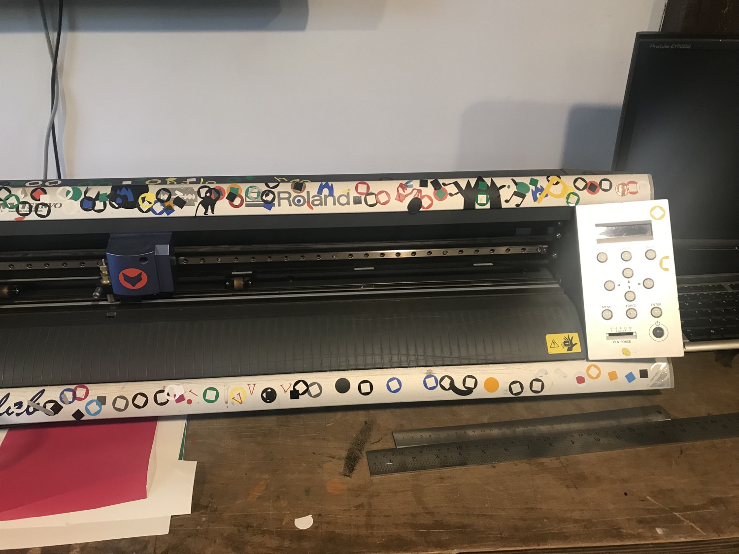
There are only two important settings that can be adjusted for the vinyl cutter - speed and pressure (sometimes called force). Speed is calculated in cm per second and the force in grams of force. Intricate designs call for slower speeds while bulky designs can go at the highest speeds. Thin easy to cut materials need very little force but thicker stronger materials need more. The blade can also be replaced with different angled blades to improve performance or pens if you prefer to draw. Settings I used were 10cm/s at 150gf.
Step by step guide
- Make your design ready for the vinyl cutter. Outline text, make everything true to scale, rotate, duplicate, give colors, do all the things you can do before hand - don't' forget to check the size of your stock. Change all lines to no infill and 0.003 linewidth.

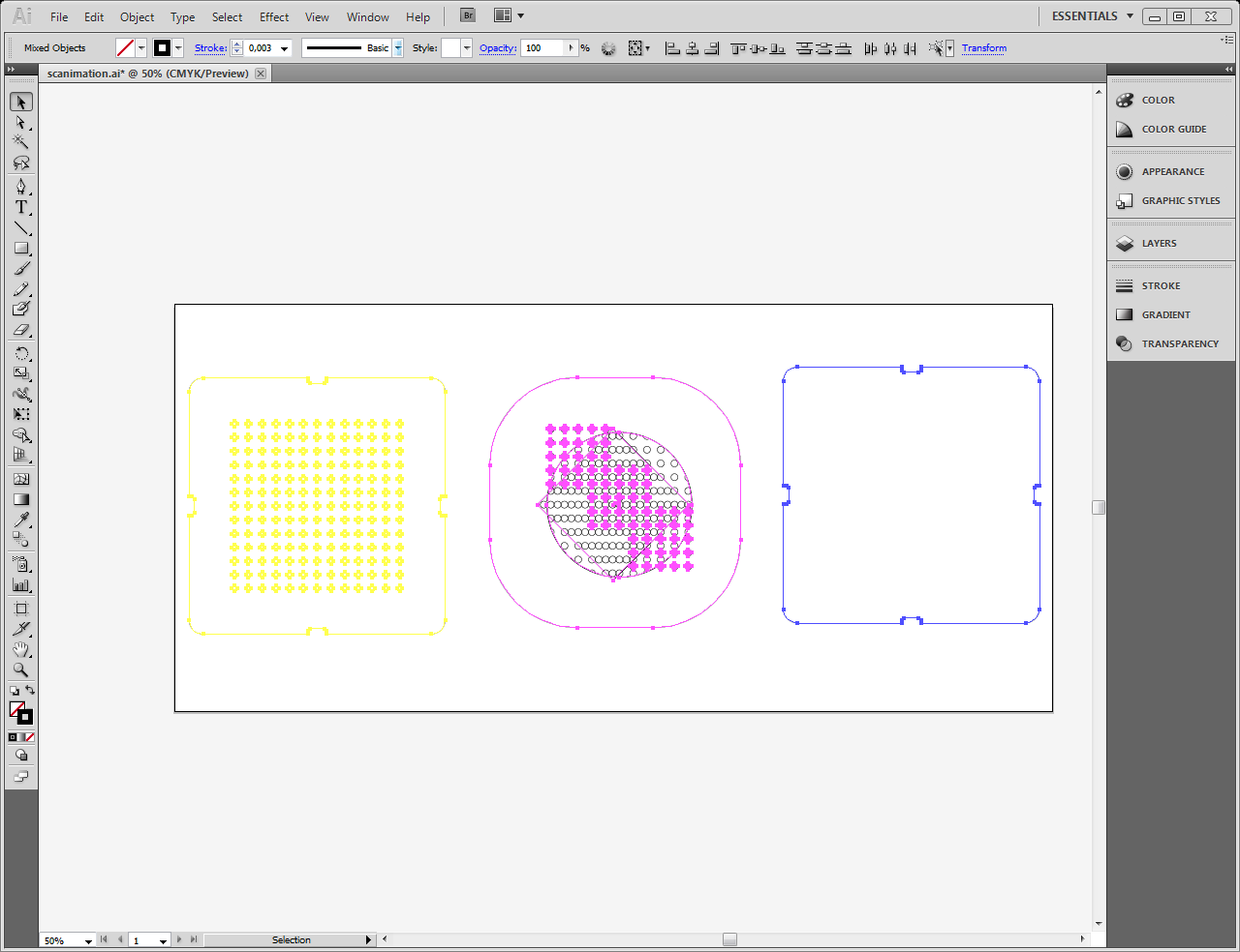
- Export your design for the vinyl cutter and put it on a USB drive. The machine directly cuts from Illustrator so any vector compatible with Illustrator will work.
- Switch the machine on and put the stock material in the machine - use the lever on the left side of the machine to lift up the wheels. Pull the material with the cutting side on top through the machine. Make sure it is in straight and check if the wheels are in the white positions and on top of the material. Push the lever back to the original position.
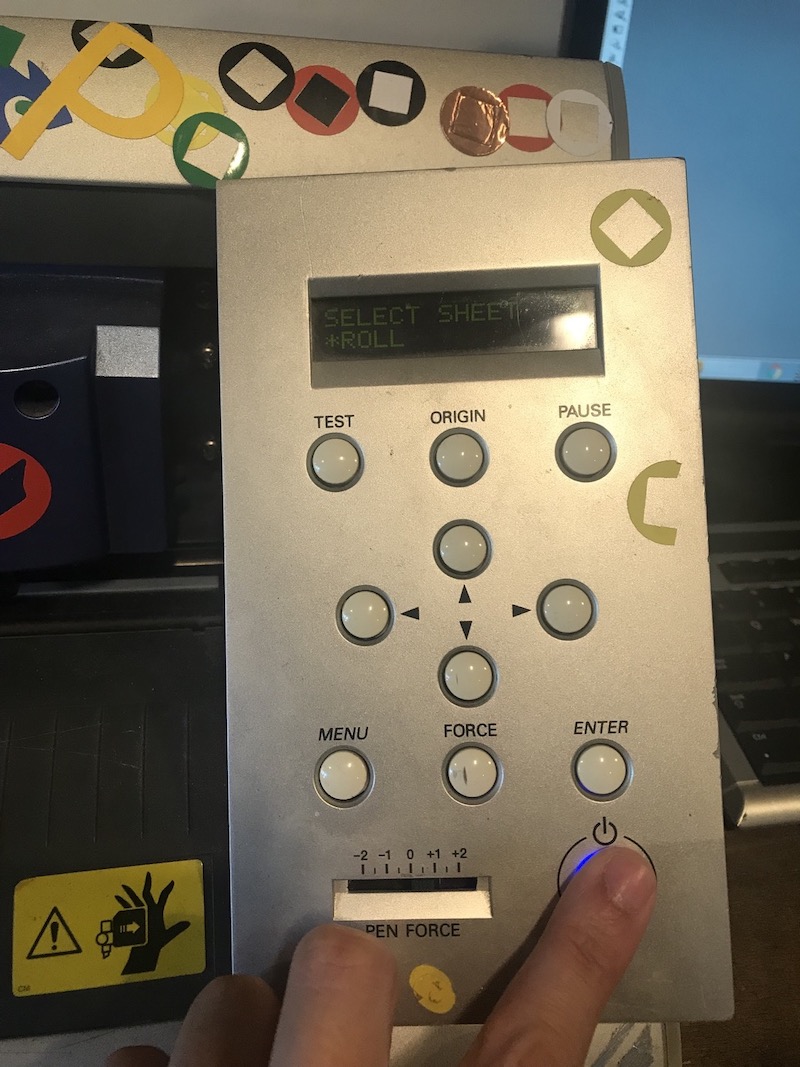
- The machine will now ask stock we will be cutting - a piece or a roll - roll is always a good choice. If you pick piece it will check the width and height of the stock. If you pick roll it will just look at the width. Press enter to confirm.
- Using the arrow keys move the material back through the machine, this way we don't waste any materia. Press and hold 'origin' to tell the machine this is where we want to start.
- Now it's time to make a test - press 'test'. The machine will now cut a small square and triangle. Using the arrow keys move the material to inspect the cut - try to peel of the square but not the triangle using a tweezer or weeding blade. If you are able to only remove the square but not the triangle you have the correct settings. Make sure that the wheels that hold the material down are located on the white spots.
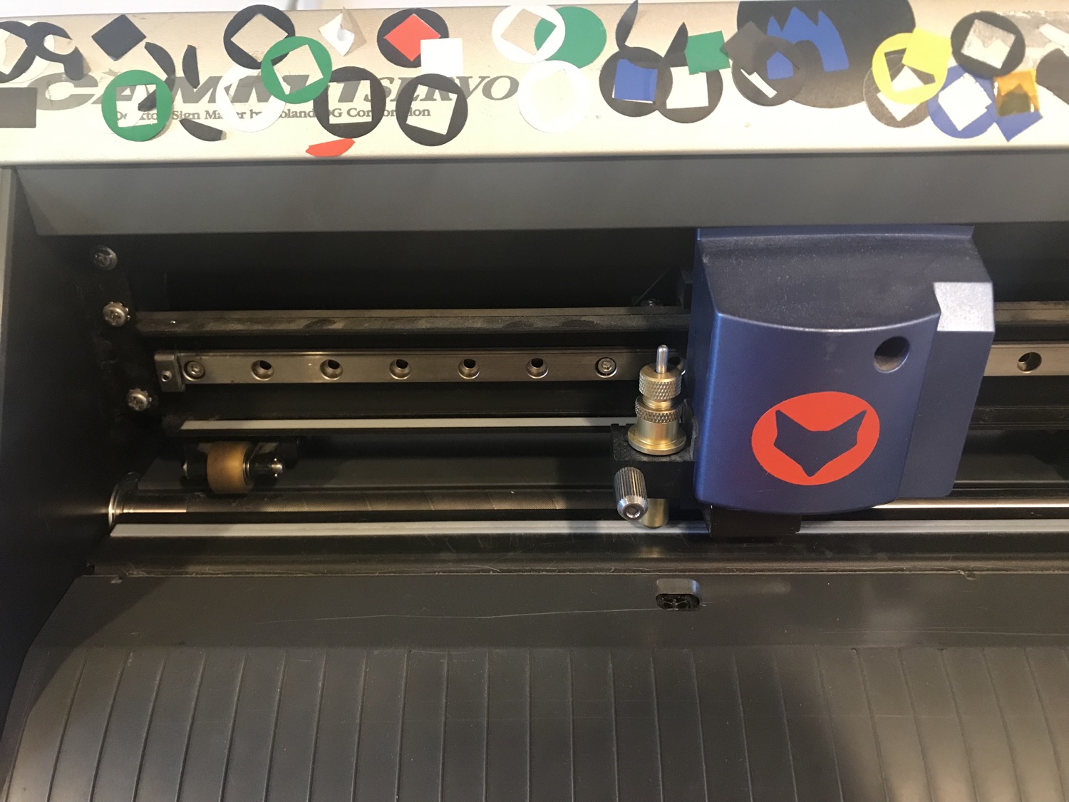
- Move the material back to where you want it to start and press and hold 'origin'.
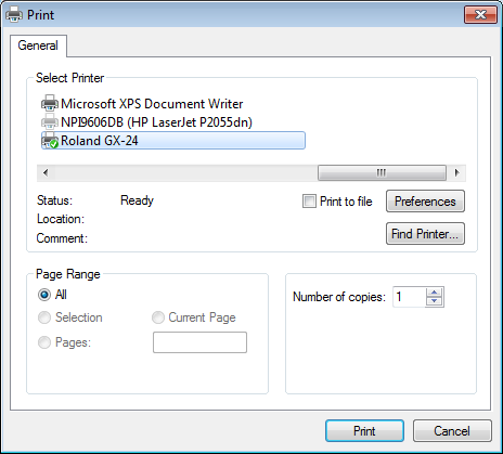
In Illustrator go to File > Print. Click 'Setup'.
Select Roland GS24 and open 'prefrences'.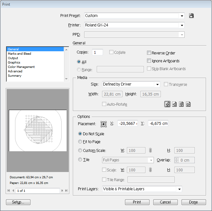 Click 'get dimensions from machine' and check if the dimensions on the machine and on the computer are now the same. Click print. Check again in the preview if the dimensions are correct. Check if auto scale is disabled and your design is in the bottom left corner of the preview. Click 'print'.
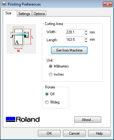
When the machine is done cutting remove the material by opening the lever again.
- When you are done, switch of the machine and leave everything tidy (or tidier than you found it).
Best practices and common mistakes
- The machine is cutting double lines - you forgot to set a very thin line thickness.
- For flexfoil always mirror your design!!
- When peeling of the scrap material try to do it in small pieces.
- When making letters peel from right to left and bottom to top (most fonts release better this way.
- Use registration marks if you want to use multiple colors.
- Always make a test! even if you are sure you have the right settings, the blade could be dull.
- Don't make stickers longer than 150cm in one cut - anything could happen.
- Sharp corners become dull - slow down the speed and check if the blade is sharp.
- If you cut with to much pressure the backingpaper will stick to the parts your peeling off - lower the pressure.
Scanimation
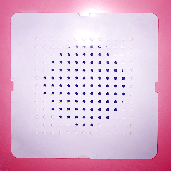
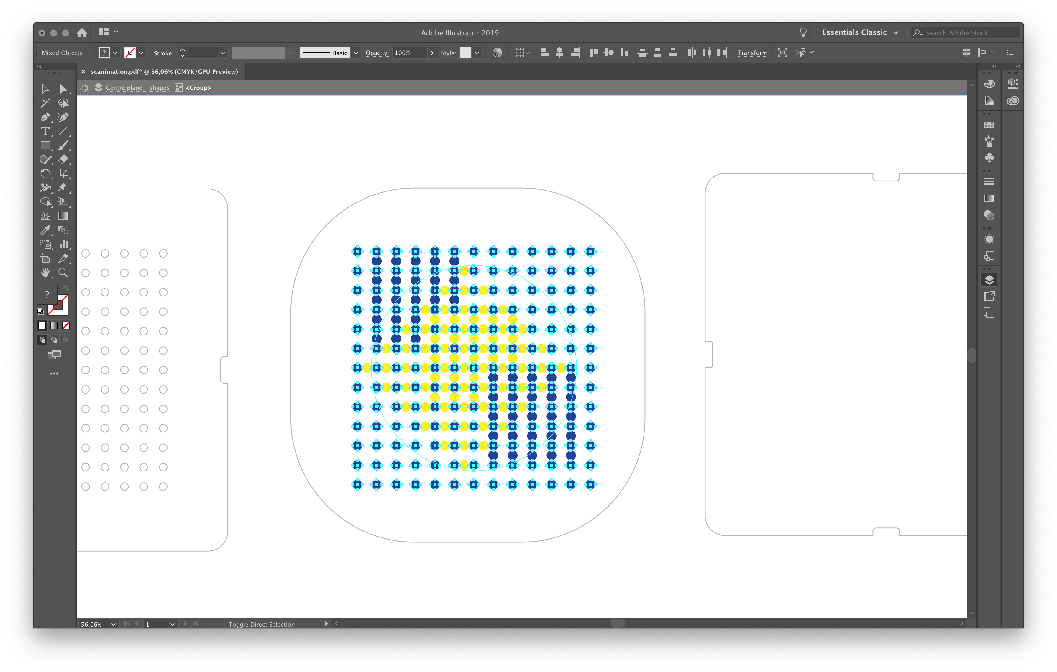
I made my design from last week during the computer aided design week is split up in three layers - top, middle and bottom. All layers are made from cardboard and the illustration on the middle one is made with two different layers of coloured vinyl.
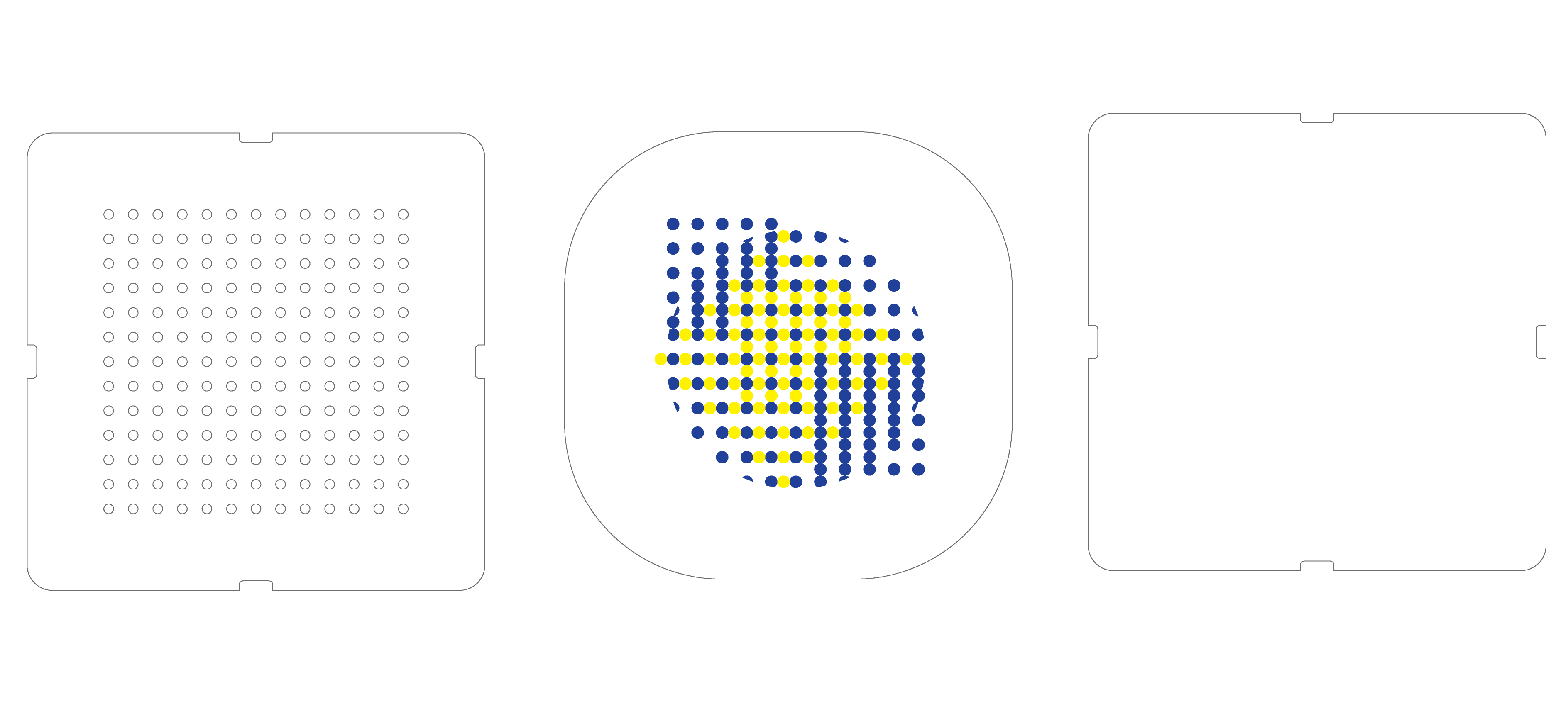
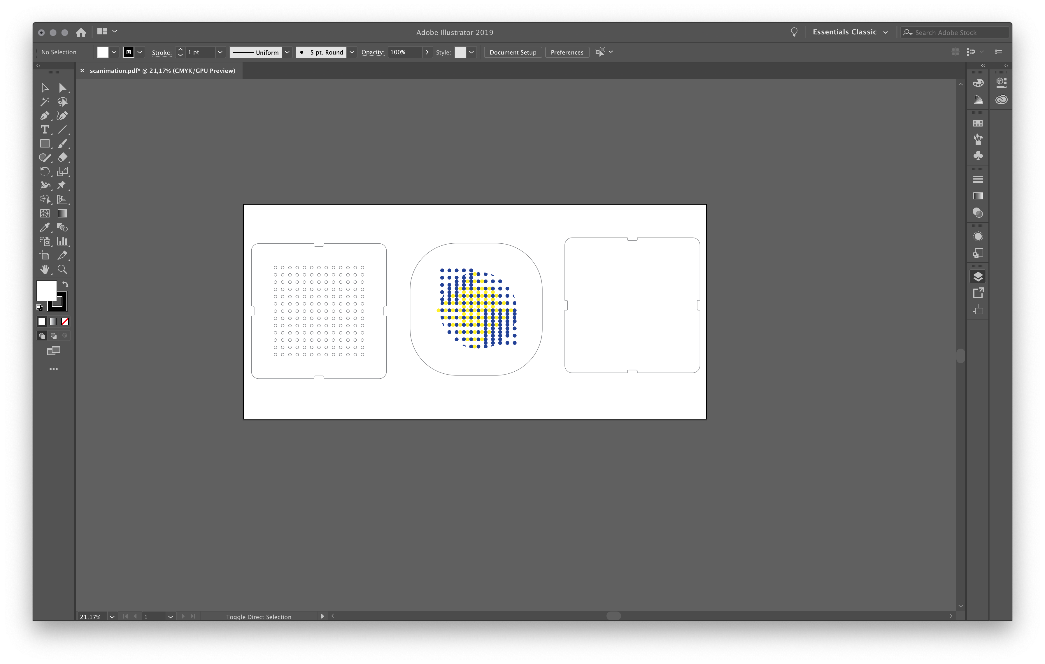
It's a bit hard to see in the image but I made clipping masks for each 'scene' of the animation.
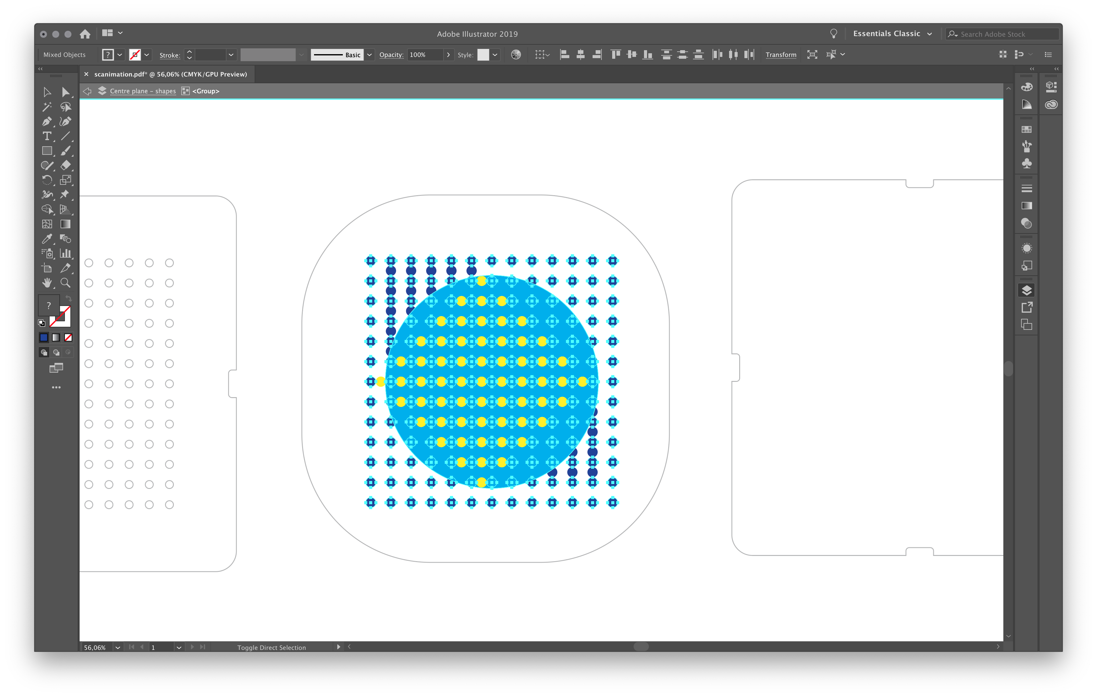
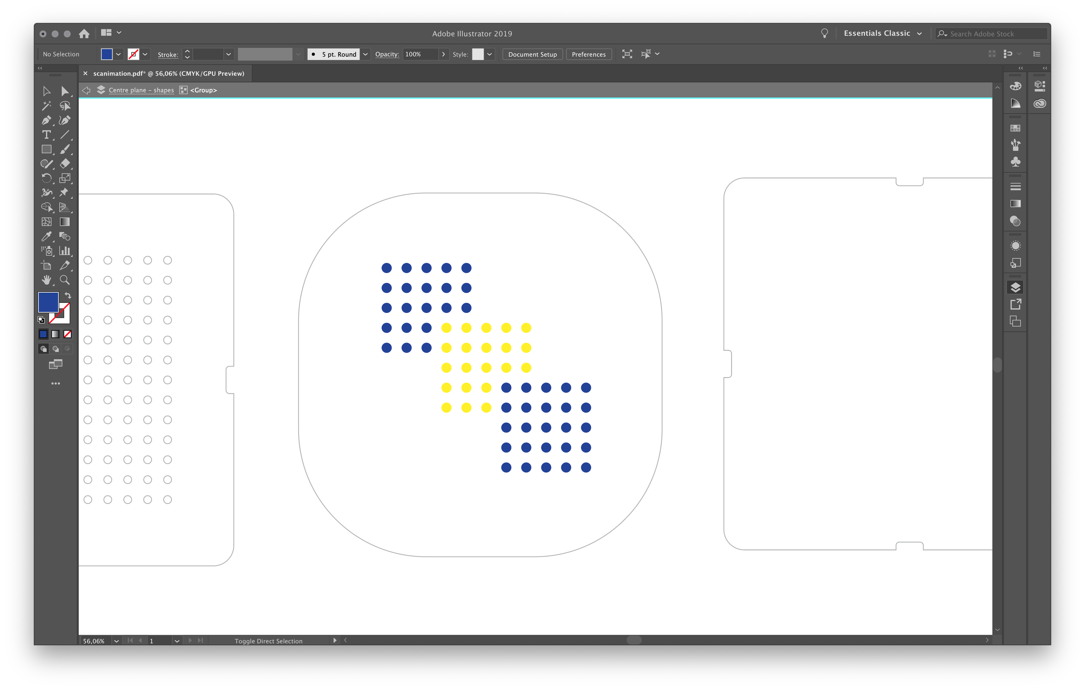
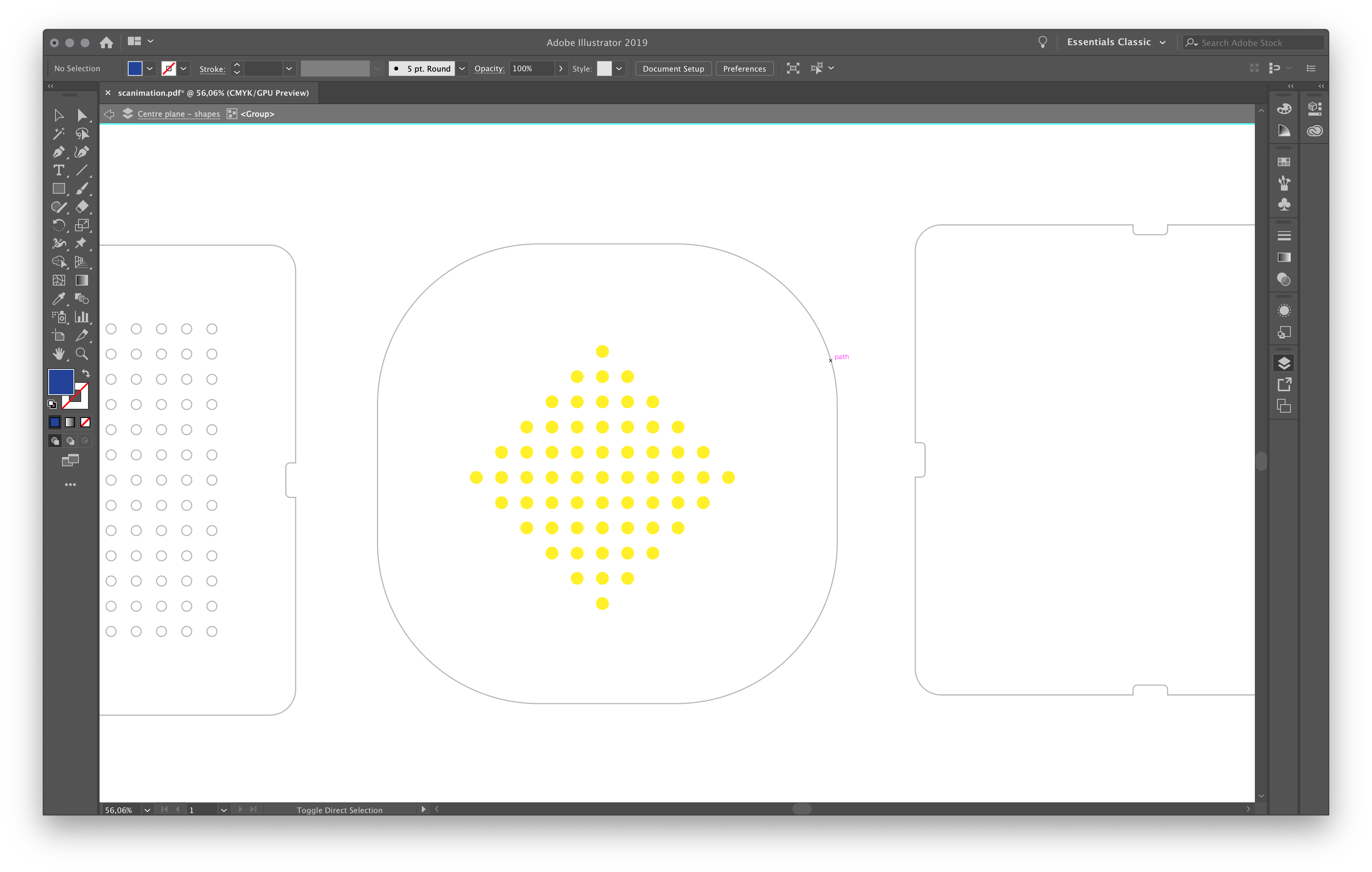
Here you can see two of the other scenes that are drawn without a clipping mask since these are really simple and made out of full circles.
The paper parts were definatly the easiest to make but scared me the most since I never tried it and the detail level of the grid pattern is quite high. I asked Jona from Oh Pop Up for some advise. She told me that she wouldn't make the holes smaller than 3mm and to cut at the highest speed (10 cm p/s) with semi high pressure (150gf) using multiple passes.
The cutting mat I used came with my vinylcutter (Silhoutte Cameo) and is 12 x 12 inch. The only cardboard I had at home was from the Hema, it weighs 210 g m2 and has bright patterns on one side and is white on the other. The cutting mat has a protective layer to keep it sticky that I had to take of. After this I used the grid on the cutting mat to position my material (right side up).
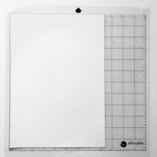
I made a test and started with 6 passes, this clearly cut through the material but also was clearly visible on the cutting mat. For the second test I only made 3 passes and this looked right - very little marking on the cutting mat and very sharp cuts. I cut all three parts and removed all the left overs from the cutting mat and put the protective layer back.
After this I had to cut the vinyl for the "image" on the middle layer. This is where I got a little bit worried because I forgot registration marks on the cardboard middle layer. Since the alignment needs to be really percice I needed a solution. If had known this beforehand I would've drawn some registration marks on the cardboard and both coloured layers. My solution was to cut the cutting line for the cardboard as well, this was a little bit more wastefull but worked really well. I cut both vinyl layers and peeled away everything that I didn't need. Using transfer paper I moved the first vinyl layer to the second. Since none of the colours overlap this was pretty simple. Using the surrounding shape it was also quite simple to align them. Using the backing paper with now both colours of vinyl I moved the stickers onto the cardboard. The aligning was a bit more tricky but with a set of extra hands it was quickly done.
I checked with the top cardboard if the image was visible and everything looked right. Than I glued the top and bottom layer in the corners together with the 'loose' middle layer inbetween. I think this project is pretty fun to make and I would love to make it out of wood with a string to hang it in four different orientations. If I were to make another paper one I would make some paper tabs to make the top and bottom cardboard in one piece and more profesionally glued together.
