Computer-Controlled Machining
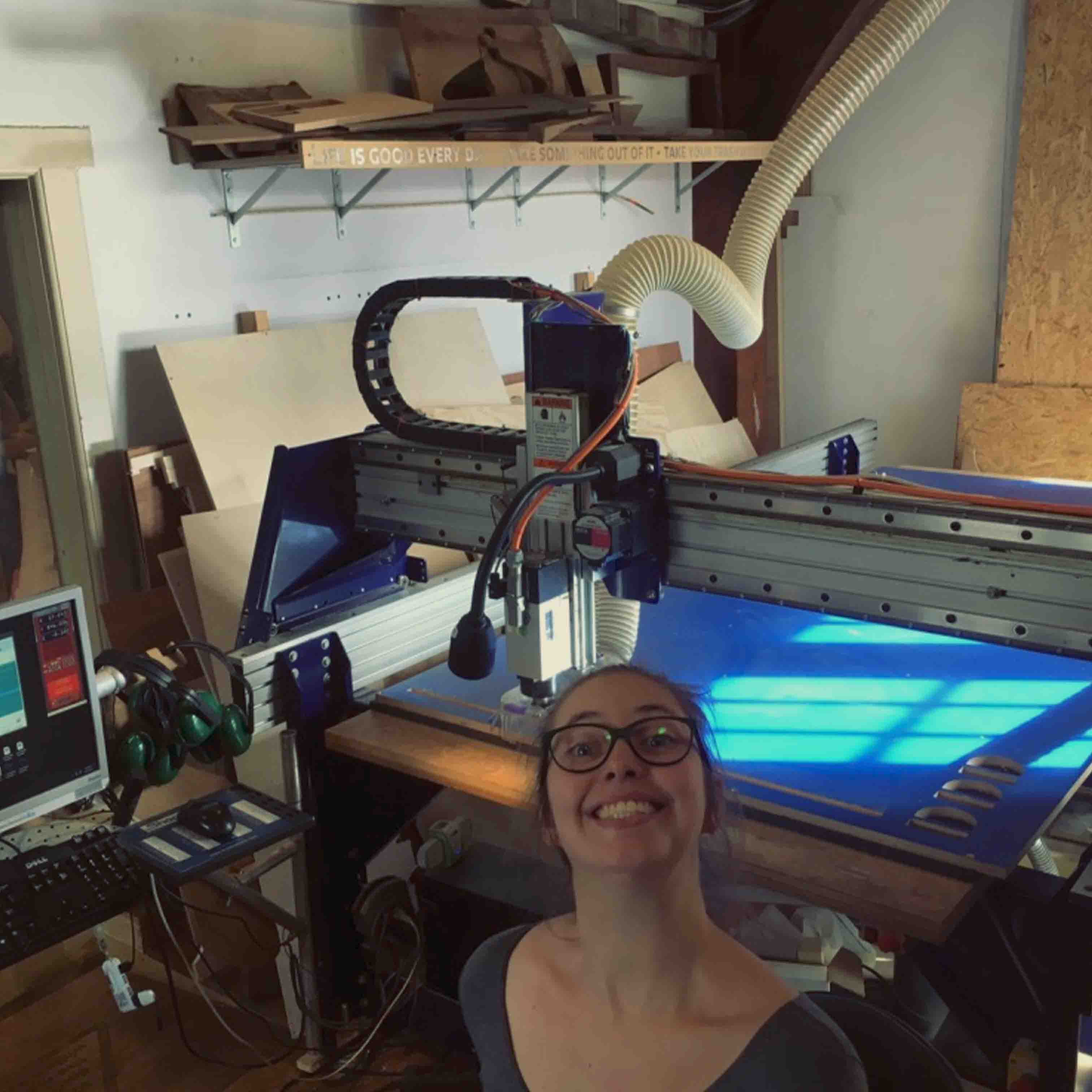
The Shopbot milling machine is a full size CNC milling machine and its superpower is making things as large as furniture (or smaller things). This machines CAM software works in two and a half dimensions (2.5D) meaning you are cutting a part that has multiple flat features at varying depths. The Shopbot CNC machine works with a range of materials: wood, plastic and aluminum are no problem. 3D milling is also possible on this machine but out of the scope for this week . Working in three dimensions (3D) means that you have the ability to control at least three axes simultaneously. 3D contouring can then be accomplished by creating curves that use all three axes at once.
Milling tools
Hardware
Shopbot
Software
Vectric
Fusion 360
Tools
5 mm straight 2 flute milling bit
Materials
Multiplex full sheet (1220x2440mm)
Saftey
Like always, safety comes first. Through the high speed of the spindle and the movements of the machine accidents can happen if you’re not paying close attention. Keep in mind that you protect your eyes against flying pieces of wood or metal, your ears against the noise and your lungs against dust. You are also responsible for the people around you so don’t forget to inform them on anything safety related. If you are the one operating the machine, you will be the one that stays with the machine and are responsible for it.
During operation always have the extractor switched on and wear ear and eye protection.
Milling bit basics
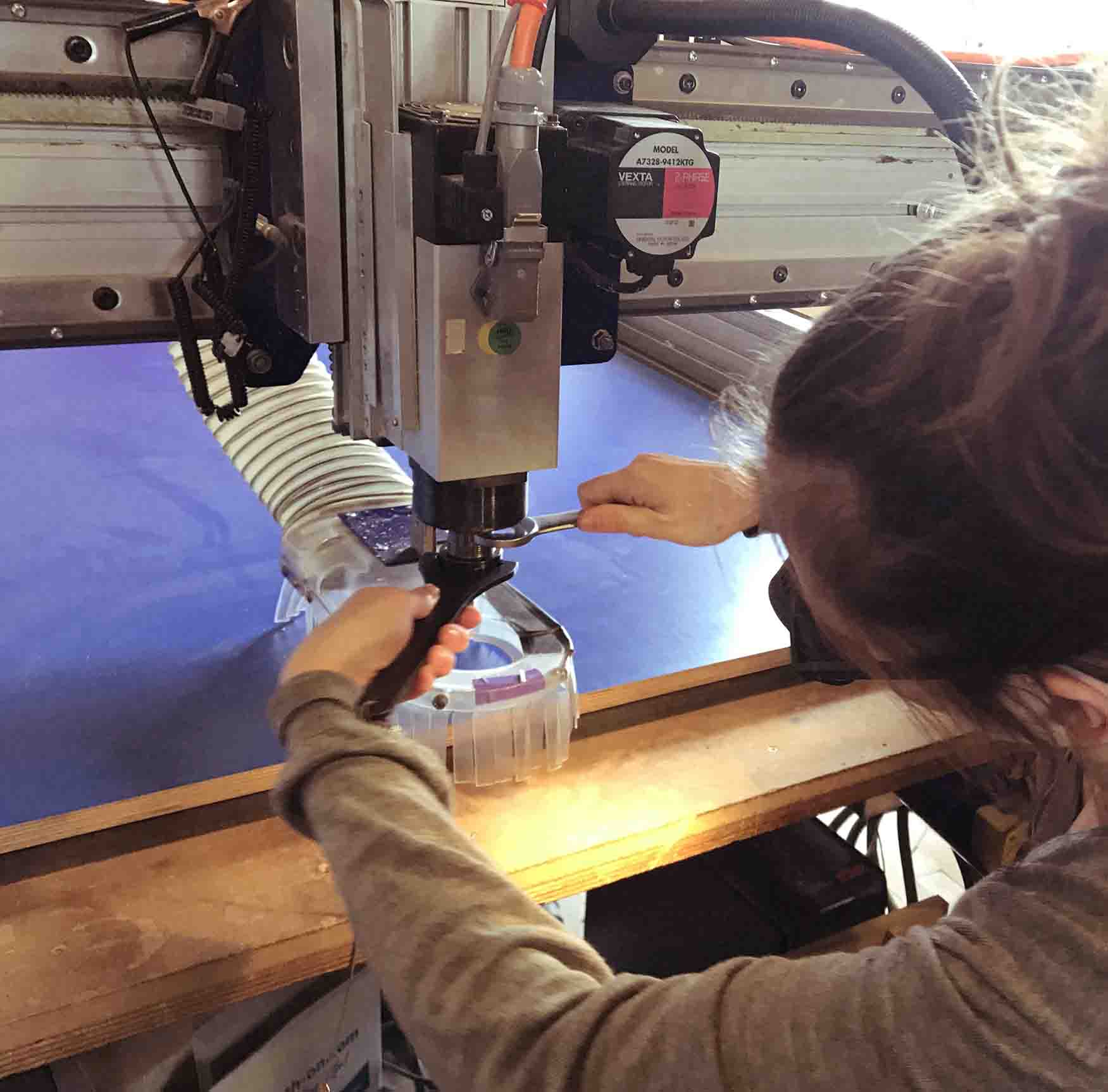
To mill material away you use a milling bit (don’t ever confuse this with a drilling bit). The milling bit is attatched to the spindle using a collet and nut. There are a lot of different milling bits and each serves it’s own purpose. The basic anatomy of a milling bit usually the same.
Overall length: total length of the milling bit.
Shank diameter: width of the top (non cutting) part/intake.
Cuttng length: length of the cutting part.
Cuttng diameter: width of the cutting part.
Flutes: cutting spirals can also be straight.
Down spiral/up spiral: direction of the flutes.
End mill: milling bit with a flat end.
Ball nose: milling bit with a radius shaped end.
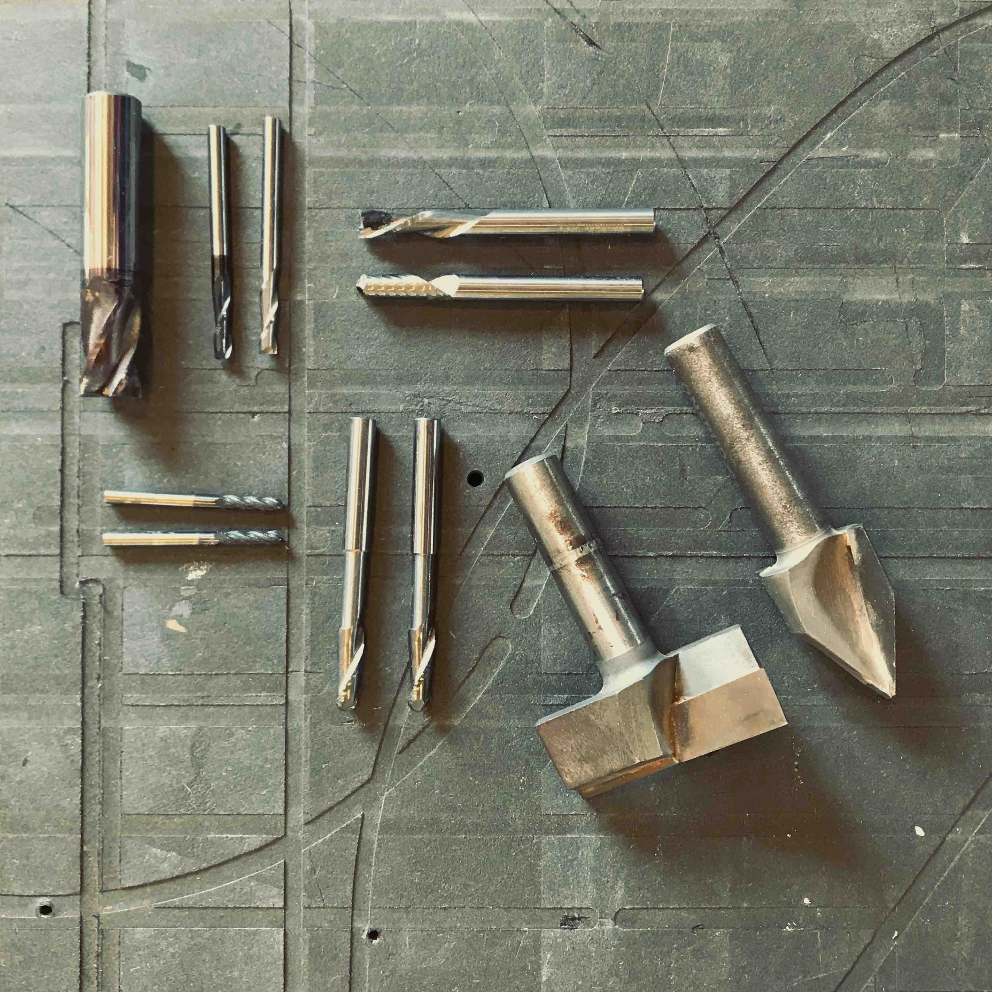
Choosing the right milling bit can be a bit of a challenge. There are quite a few different ones. There are some basic things to keep in mind when selecting them. In milling most questions can be answered with the holy trinity: it depends on the design, the bit and the material. So if we know our design and material we know what milling bit we can use.
Shank diameter: check if you have the right collet, there are metrical and imperial sizes, don’t mix
since you will break them. A 2 mm shank requires a 2 mm collet and a ⅛” shank requires a ⅛” collet.
Cutting length: always needs to be equal or longer to the deepest cutting depth of your design
Cutting diameter: ideally is the largest possible based on the smallest parts of your design.
Flutes: 1 or 2 flutes allow you to go fast and clear out material quickly, 3 or 4 flutes will give you a
better finish. But more flutes also create more heat and have less ability to clear out dust so you will have to mill slower.
Down spiral/up spiral: Down spiral milling bits are most commonly used for wood, it has a good ability to enter cut depths. It makes the finish of the top of the material usually a bit cleaner compared to the bottom of the material. Up spiral bits do the opposite but can be great for cutting for example metal or hard materials where it’s key to get heavier dust particles out of the cuts.
End mill: Great for 2D, 2.5D and even 3D jobs. Gives a flat surface and straight pockets.
Ball nose: Great for 3D (steps will be less obvious) or can be chosen for esthethic reasons.
There are also special milling bits for example:
V-bits: these are V shaped and come in different angles, great for champers and signs.
Surfacing tools: these tools are only used for surface, usually have a pretty large diameter.
PCB drills: specialised for cutting your own circuit boards.
The milling bit should fit in the smallest gaps/corners/holes in your design. For furniture or larger objects a 6 mm cutting diameter would be a good choice. Why? You can go pretty fast and the right cutting length should be easily available and it works well with the smallest features in your design. Using plywood? Go for less flutes it’s pretty soft and easy to finish. Using hardwood? It might make sense to use more flutes since it will give you a better finish. For example if you want to cut a small delicate decorative piece you might want to go for a 2 mm inch milling bit since it fits the design better. It will take you more time but since the piece is not that big it’s a good compromise. Sometimes it makes sense to even go for a selection of different milling bits. The first one being used to clear away a larger amounts of material and the second one for smaller details. Milling bits that are used should be sharp, not only for safety purposes but also for a better finish. Milling bits are a consumable with this machine.
Materials
Contradictory to the laser cutter this machine works with a wide range of materials. Educate yourself on the material you are using, safety risks and right milling bits. Keep in mind to always make tests before working on your final piece.
Material can be mounted against the spoilboard (top layer black MDF) either with screws (flush with
material) or tape. Always allow a minimum 25mm clearance in between different parts and from the
edge of the material. It’s not allowed in the Waag to use clamps or hands to hold the material in place for obvious
reasons.
Make sure the material cannot move or vibrate and keep in mind that during the milling parts
become detached from the main frame. It is not allowed to add extra screws or tape once the
machine is milling so really think things through.
Once the material is attatched to the spoilboard it should be completely flat.
Milling operations
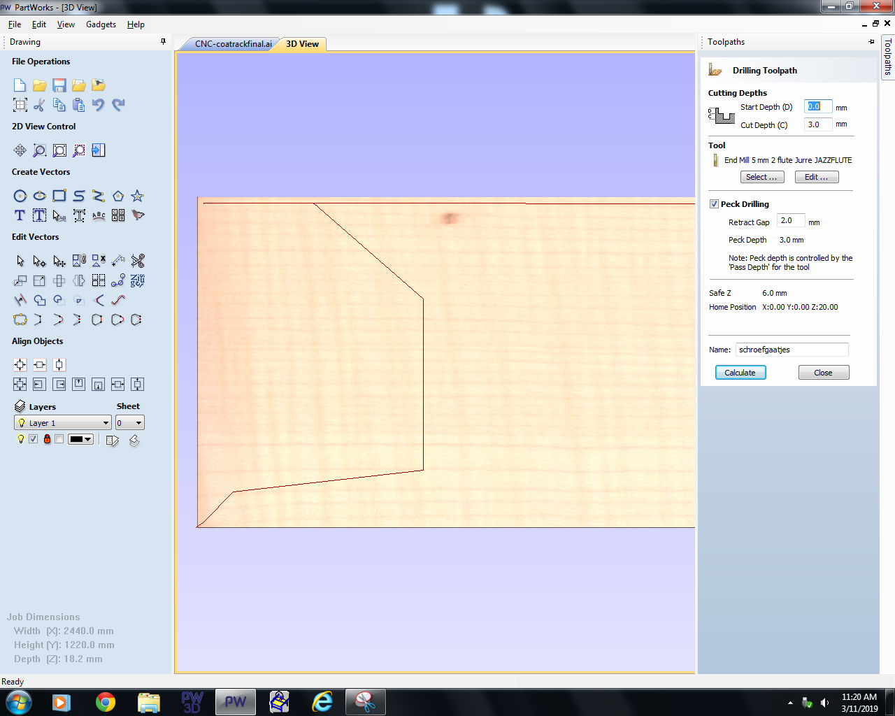
Our design can be machined in different ways using toolpaths. Toolpaths describe where and how the milling bit should go. Each operation can be done at any depth. Drilling toolpaths are used to drill holes. Most often these are used for guides to drill screws to attatch the material to the sacrificial layer. Also holes can be used to allign parts together using dowels. Profile toolpaths are used to cut out the design, this can be done outside, inside or on the line. Pocket toolpaths are the like engraving, all material within the line will be removed.
Milling
The process for this is similar to other computer controlled machines. You make a design, give it settings, create a machine file, put your material in the machine and start the job. The software supplied by the manufacturer generates code for the machine. This code gets send to the machine using Mach.
Step by step guide Partworks
- Start with your design - Draw a shape the size of your stock material and lay out your design. Do this in a way that is material efficient. Create layers for each operation and give them a descriptive name. Check for closed lines.
- Start Vectric and start a new project make a artboard the size of the material, this is done in milimeters. Check if Z zero is at the top of the material and the X and Y zero is at the bottom left.
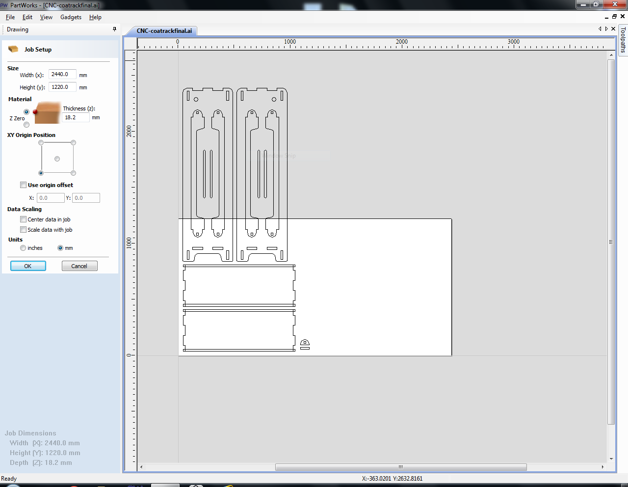
- Import your design via File > Import vectors. Check if the scale is correct. I had to rotate it and place it in the right location.
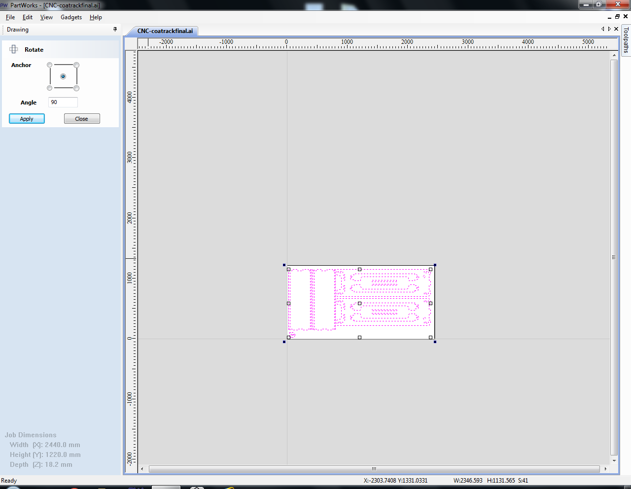
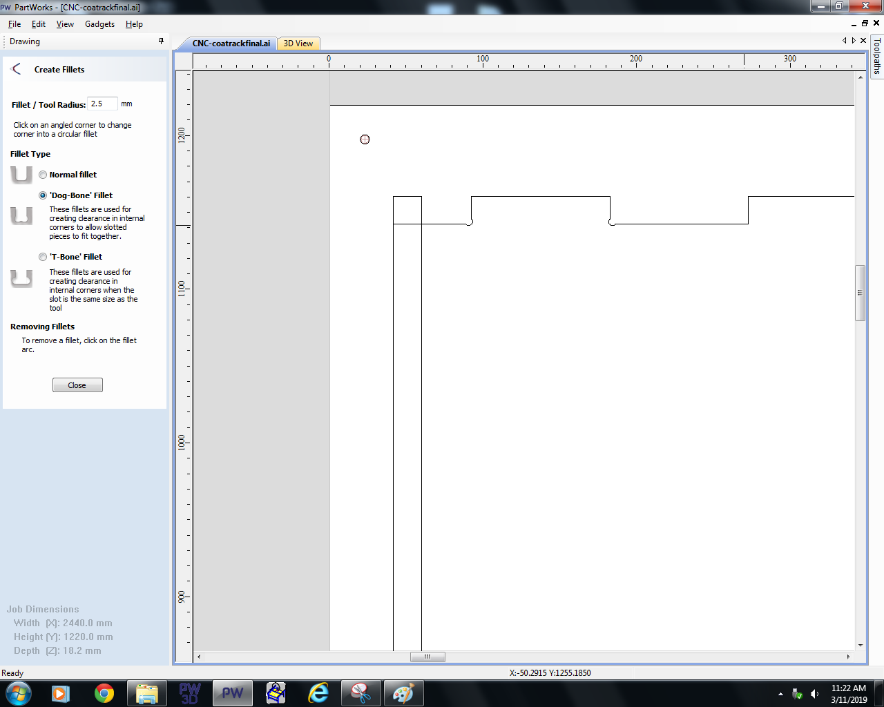
Using the fillet / dogbone command add dogbones to all inside corners.
Select a layer and give choose the correct toolpath operation. Start with holes & pockets, finish with contour toolpaths working from inwards outwards. Set the cutting depth and add tabs. Here you can see a drilling toolpath.
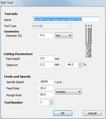
Choose your millingbit and change the feed, speed, pass depth and overlap to the desired settings.
Give your operation a descriptive name and calculate. Than do this for the next layer until finished.
Safe this file just in case.

Select all operations with the same milling bit and export them for the Shopbot.
It's good practice to always make a test cut to test the cut. Each material and milling bit can be different.
Step by step guide Shopbot
- Make sure the bed is clean, no dust, no screws no bumps. Put your material on the bed. Check if it's nice and flat. Check if the right side is up for your design.
- Switch on the machine on the right side with the red/yellow button. Make sure the key is still out.
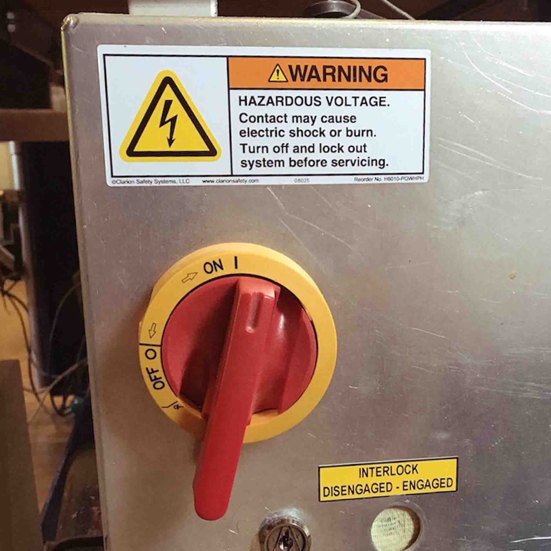
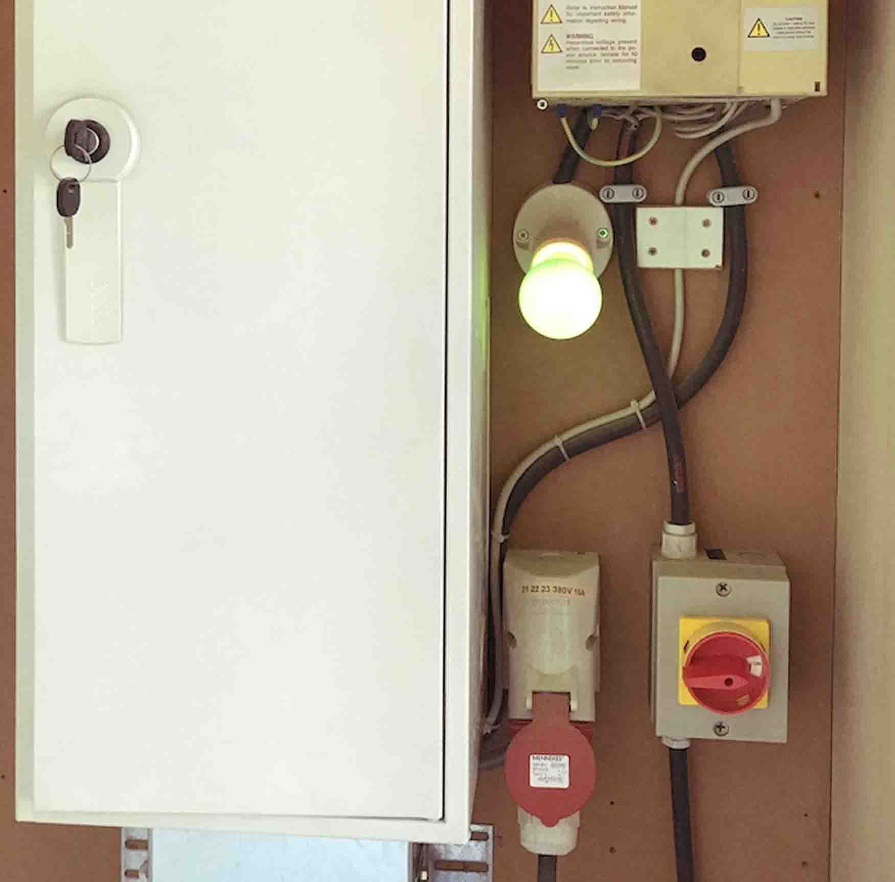
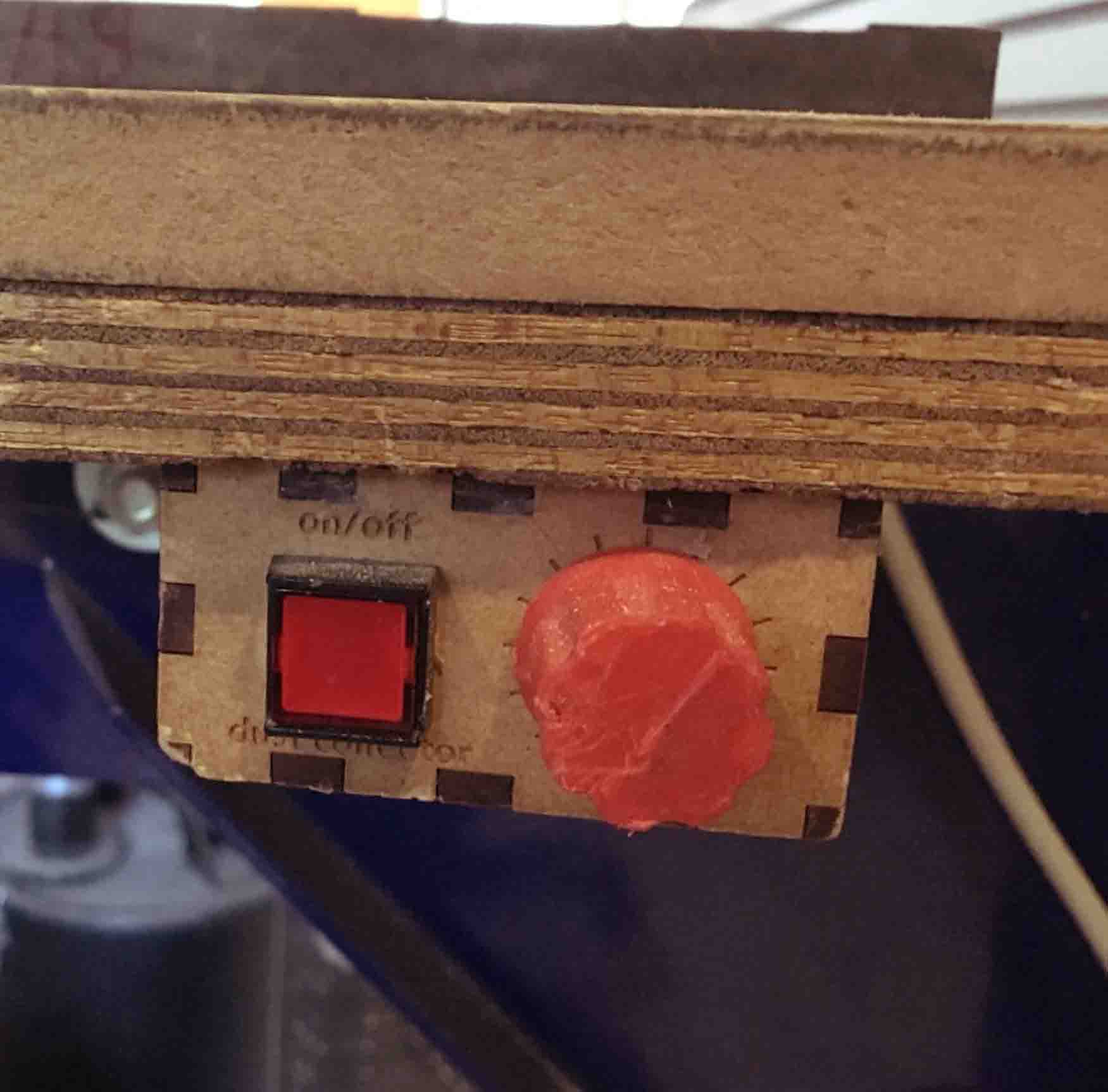
Switch on the extraction, this is a two step process. First turn on the red/yellow button in the back of the room. The second switch is on the bed itself. The left button switches it on or off and the knob controls the amount of extraction. Switch it on right before the spindle and off after the spindle stopped moving. For now just test if it works.
- Open Shopbot from the desktop.
- Press "K" and use the keypad and Page up and Page down to move to an accesible place.
- Lower the skirt (wing nut on the back) and get the wrenches to untighten the spindle nut.
- Remove the nut and take out the collet. Check that they are dust free.
- Find the correct collet for your milling bit and put it in the nut (it should click). Put them both on the spindle and tighten them halfway. Put in the milling bit and tighten further with the tools. Make sure most of the shank is inside the collet. The cutting area should still be all the way out. Double check if you have enough cutting length for the job.
- Now it's time to zero the machine. Find the machine zero by pressing the XY0 button in the toolbar. Use the Z plate to zero the probe, do this in the centre of the material.
- Move the machine with the arrow keys to the job zero (X and Y). Safe this location in the menu.
- Put your material in the machine, make sure you know where the screws are. I like to create a toolpath to drill holes, this way I can work with small margins and put screws anywhere in the material.
- Switch on the extraction and spindle.
- Open your file from partworks and start the job.
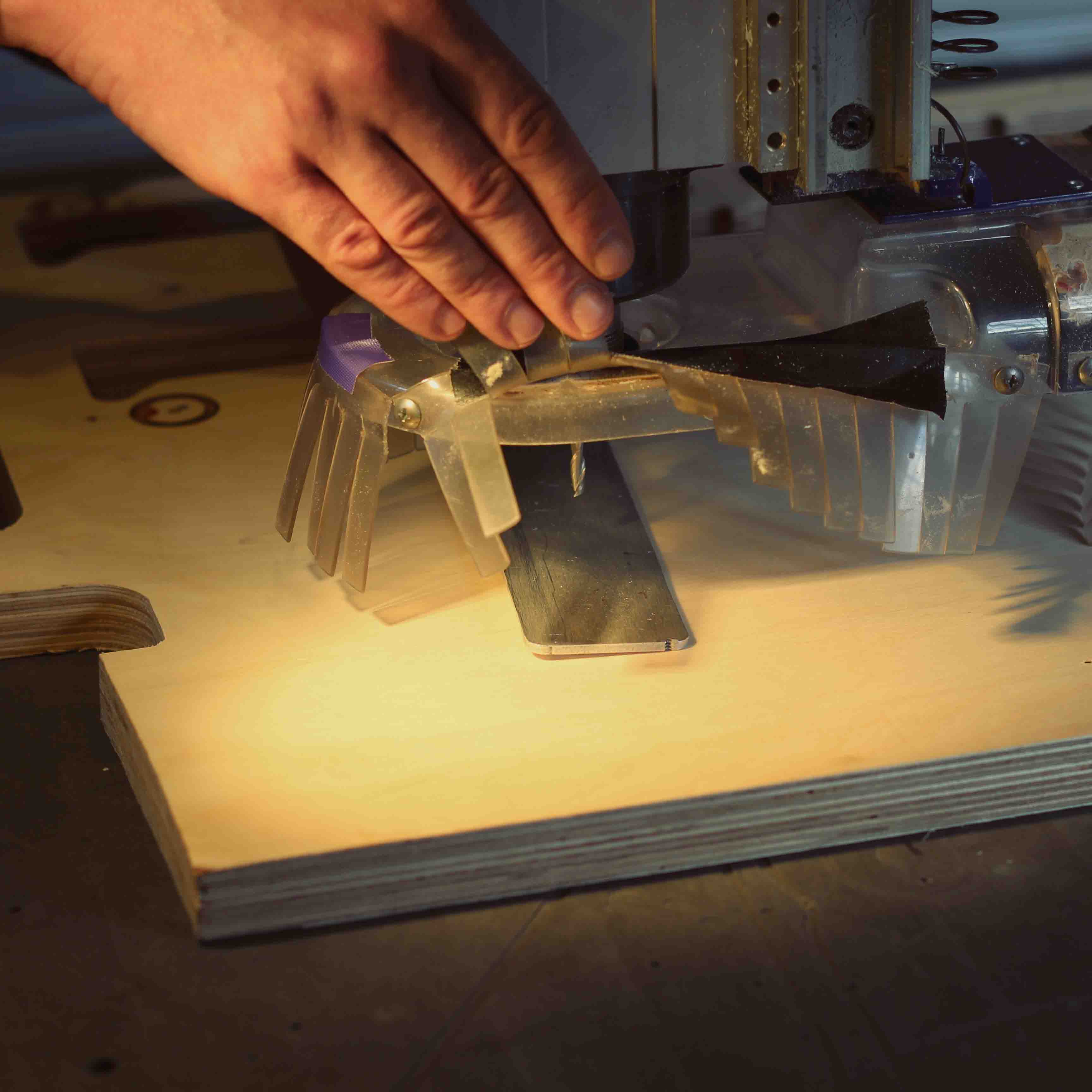
- Move the machine to the zero you want to use and zero X and zero Y in the menu.
- Get the zero Z plate from the side of the spindle. Check for connection by touching the plate against the milling bit. A light should blink in Shopbot while you do this.
Group assignment
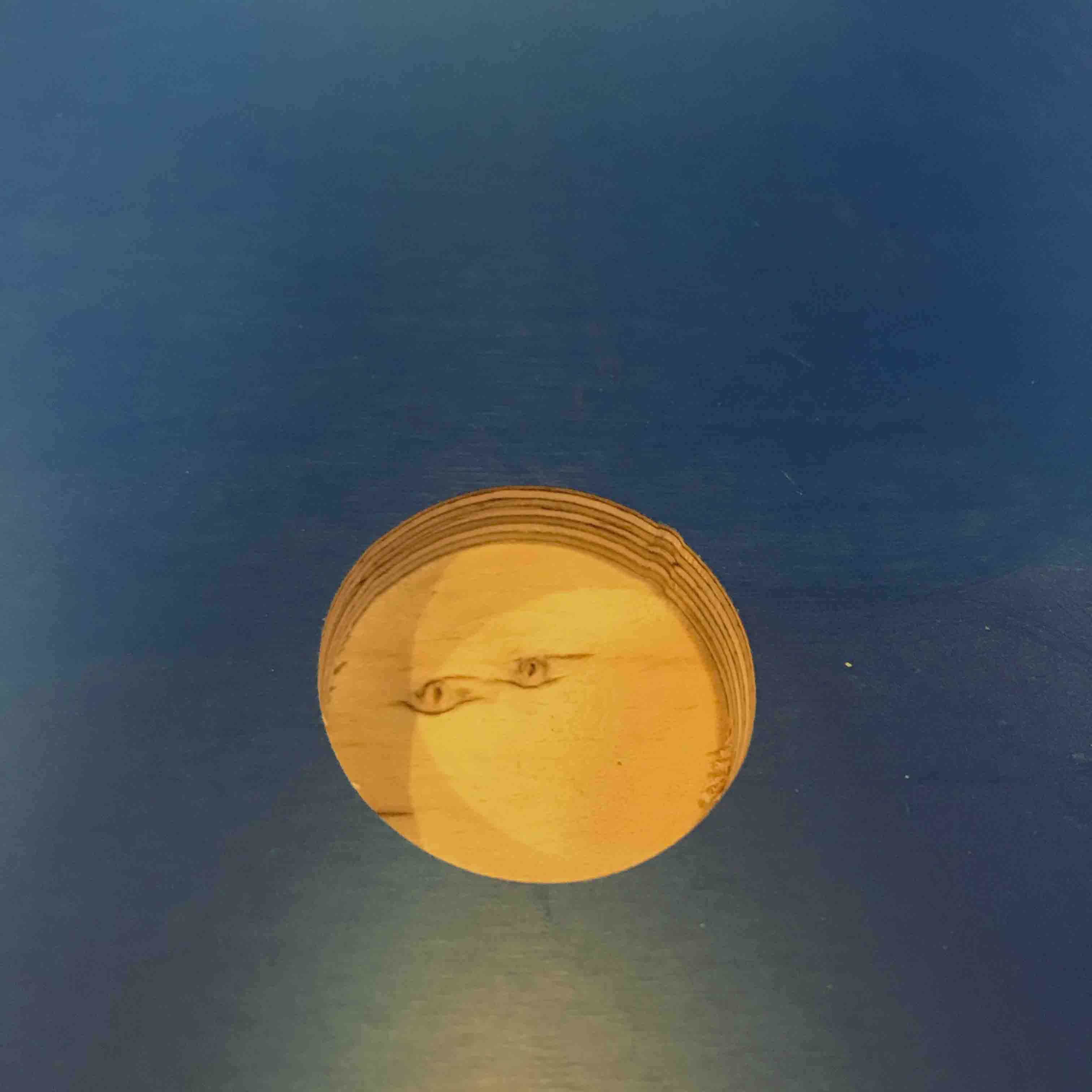
For the group assignment we made a small test file. The design has a couple features, pockets, dogbones, inside toolpaths, out side toolpaths and press fit. For the large circular pocket we tried to mill to an exact layer within the multiplex, this worked pretty well. All parts that should fit didn't really fit together. Using a hammer it almost got together. We didn't repeat the job with offsets but this was a good warning for the individual assignment.
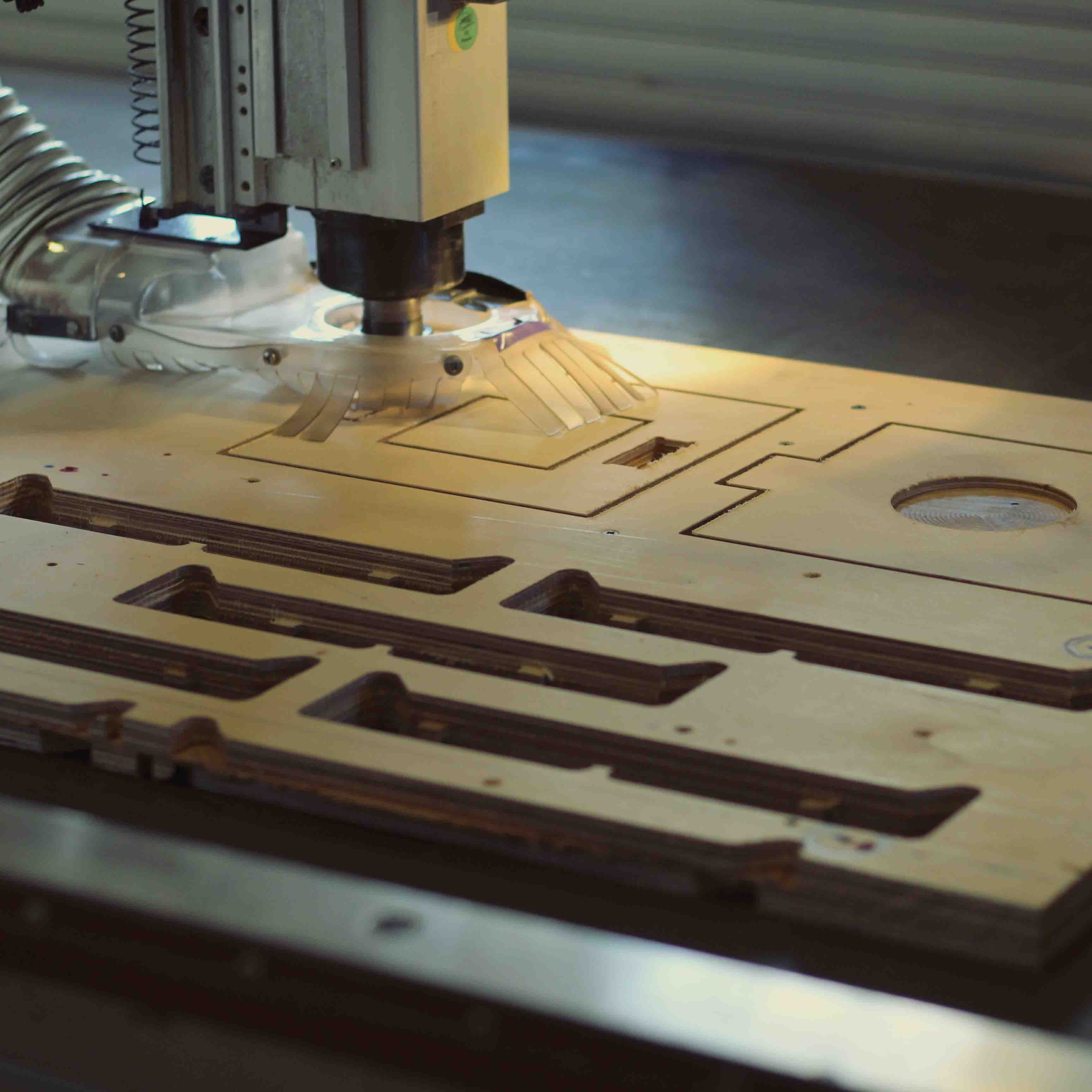
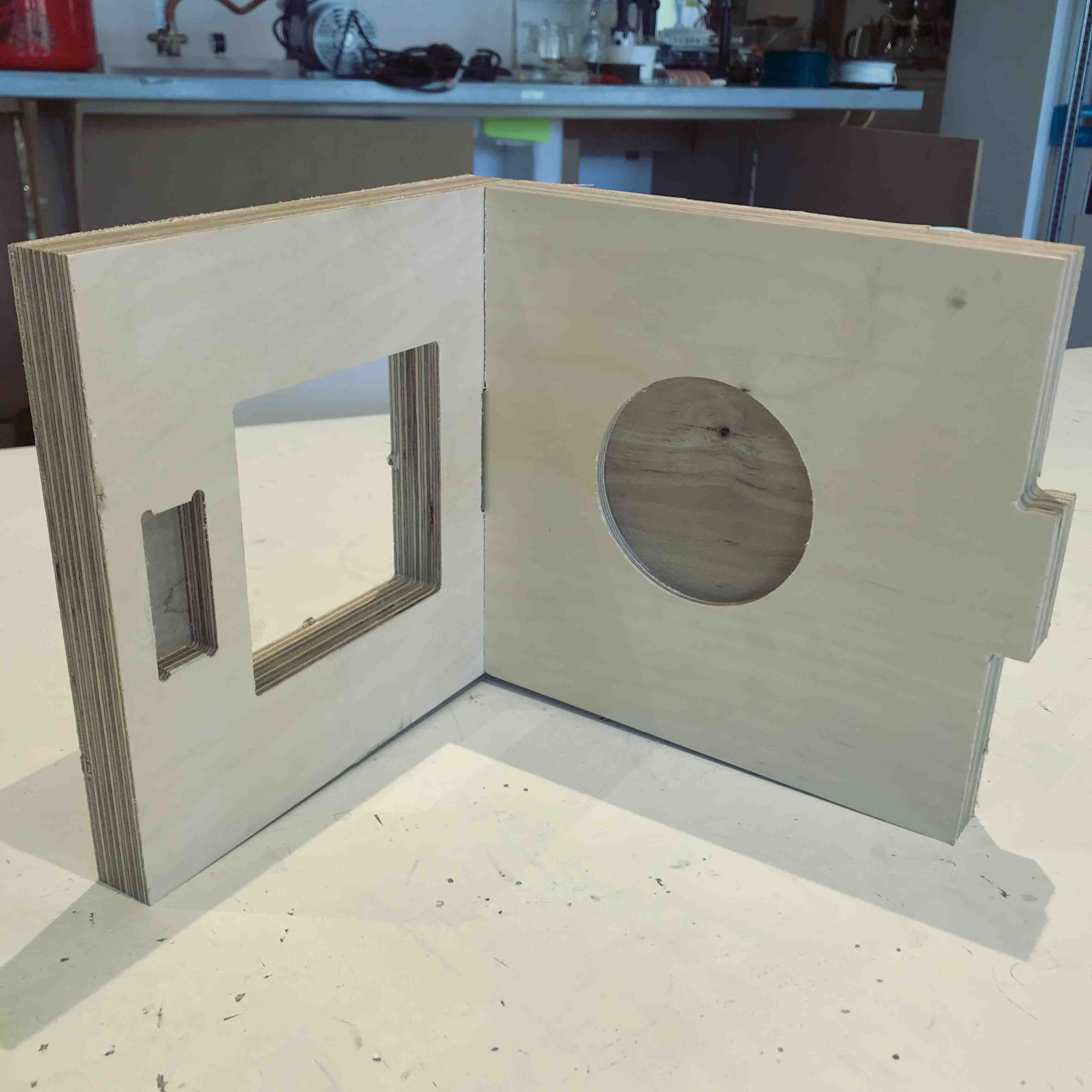
Test results
I made 3 different tests to test my press fit. For the first test I used slightly slower settings than we used for the group assignment. For the second test I wanted to see if I could go a bit faster. Since I have some experience with milling I felt like the machine should've been up for the job. After the first and second test I realised all dimensions were very off. Since the material used for this assigment is very hard I used a new milling bit for the thirth test. This improved the overall cut but I still had a lot of issues with the results.
Speeds and feeds test
| Test | Depth per pass | Feed rate | Plunge rate | Spindle speed | Milling bit |
|---|---|---|---|---|---|
| 1 | 2 mm | 20 | 20 | 18000 | 2 flute 5 mm (used) |
| 2 | 3 mm | 30 | 20 | 18000 | 2 flute 5 mm (used) |
| 3 | 2 mm | 20 | 20 | 18000 | 2 flute 5 mm (new) |
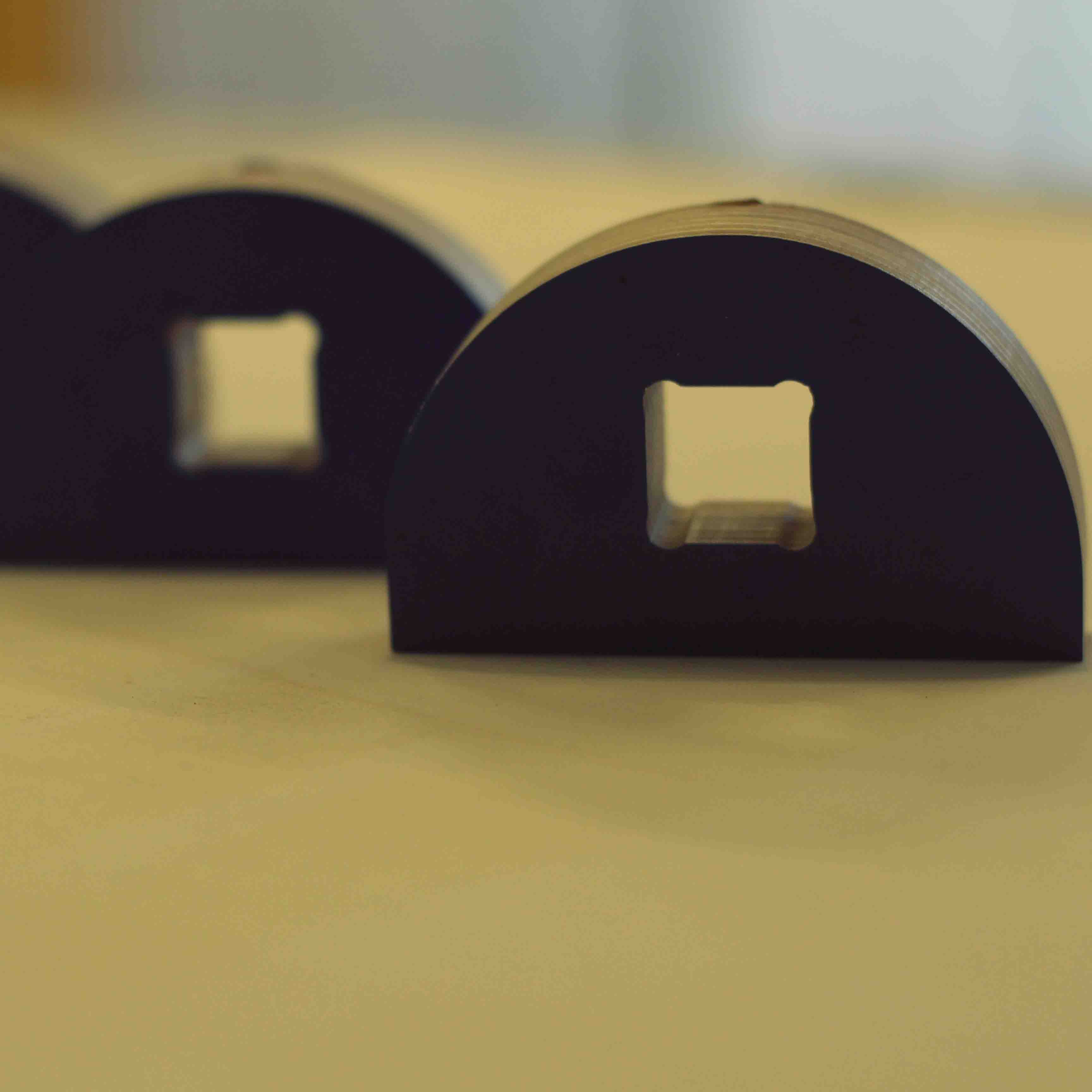
Dimensions test
| test | rectangle length | rectangle width | inside width | inside length | comments |
|---|---|---|---|---|---|
| 1 | 79.73 (-0.27) | 18.39 (+0.19) | 17.46 (+0.74) | 17.87 (-0.33) | widths differ on both sides, not square |
| 2 | 80.67 (+0.67) | 18.26 (+0.06) | 17.29 (-0.91) | 18.98 (+0.78) | same as test 1 but + bended cuts |
| 3 | 79.63 (-0.37) | 18.53 (+0.23) | 18.40 (+0.20) | 18.23 (+0.03) | dimensions differ on all sides, more square than 1 |
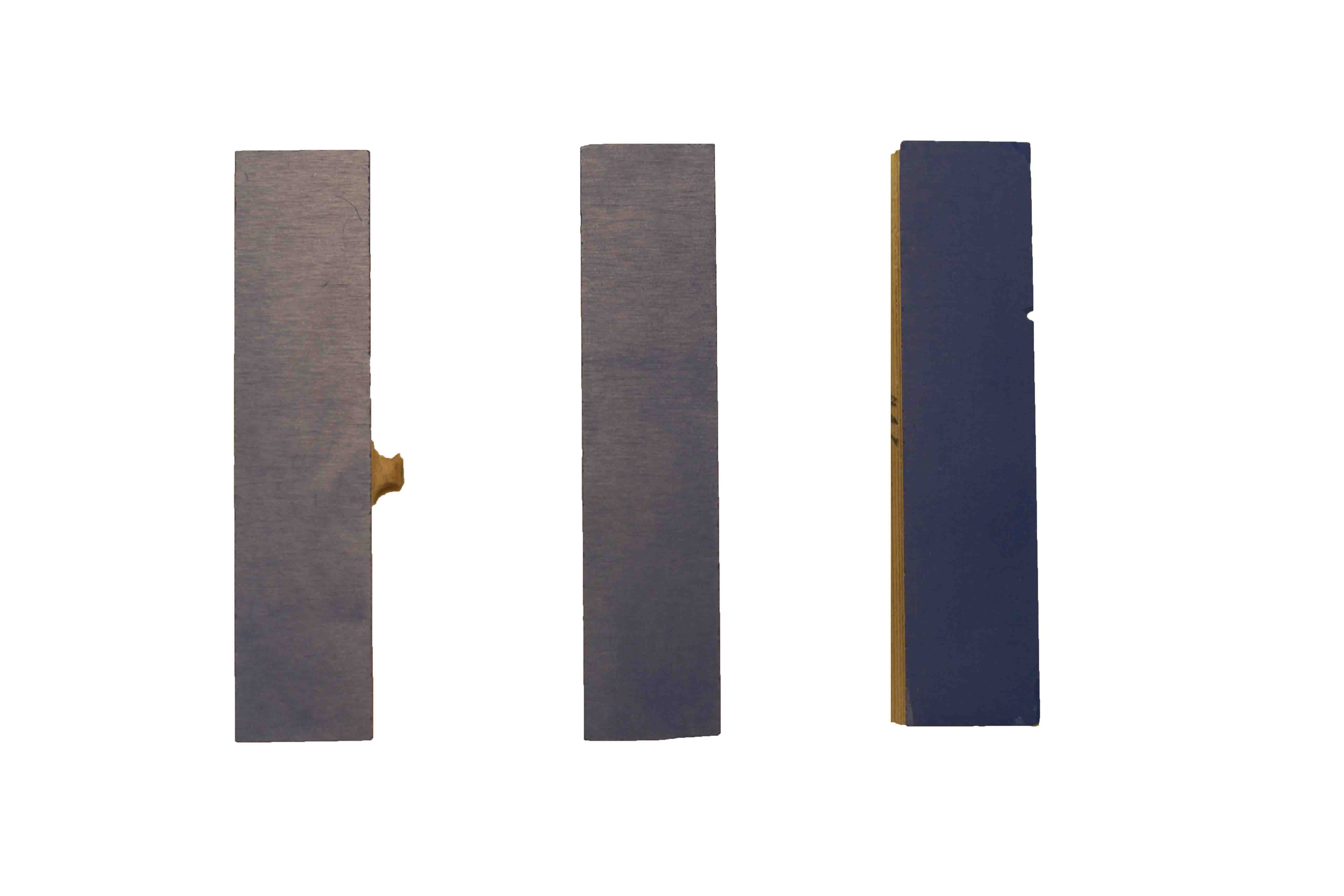
I am still not entirely sure why all of this is so much off. This is what I did.
- Checked my design against the sizes in vectric, this was identical.
- Checked for dust in the collet in collet nut - both clean. Collet is a bit worn down (+5 years old).
- Used different callipers to measure (digital and analog).
- Checked for open lines, double lines and nodes in Vectric.
- Replaced the milling bit (this helped a bit).
- Listened to the milling - some slipping noises perhaps from the collet, no crying.
- Checked against dimensions of the jobs of fellow students (similar issues but less with softer woods).
I setled with a solution where I gave all my inside contours a .25 mm offset to the outside. This turned out to be okay for most connections, very varieng results again.
Things that might improve the situation:
- Check for backlash on Z, X and Y axis.
- Retighten all axis and check bearings.
- Check bearings in spindle and axis.
- Recalibrate the machine.
- Replace collet.
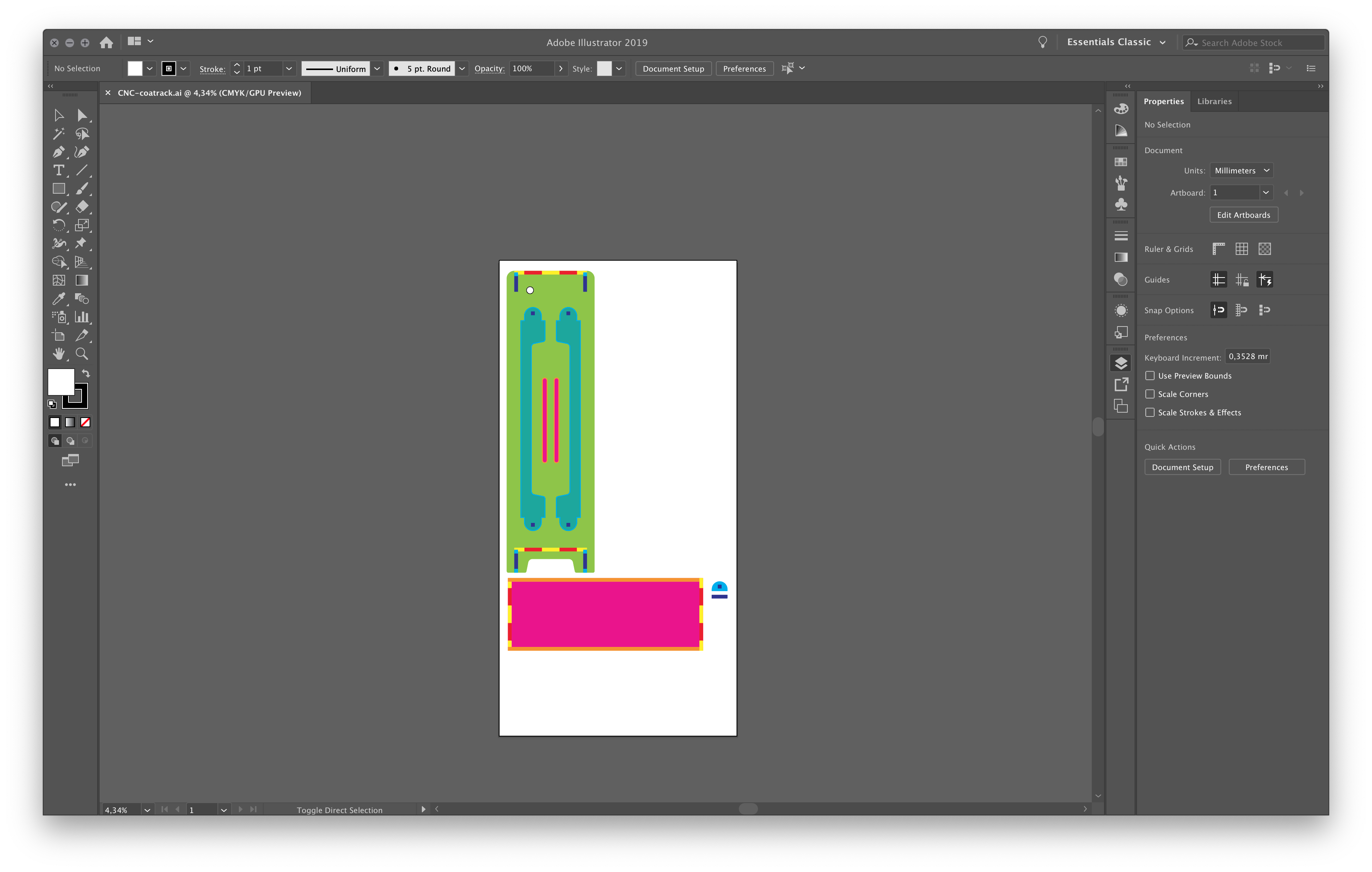
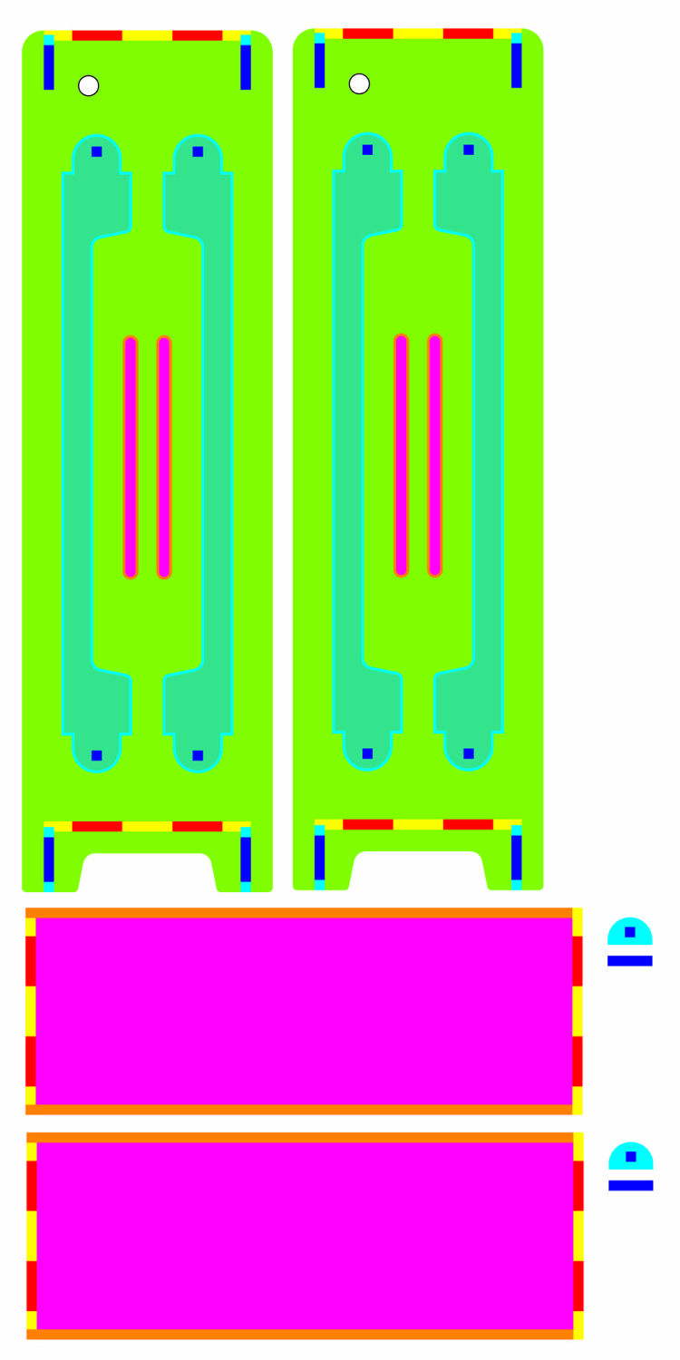
Design
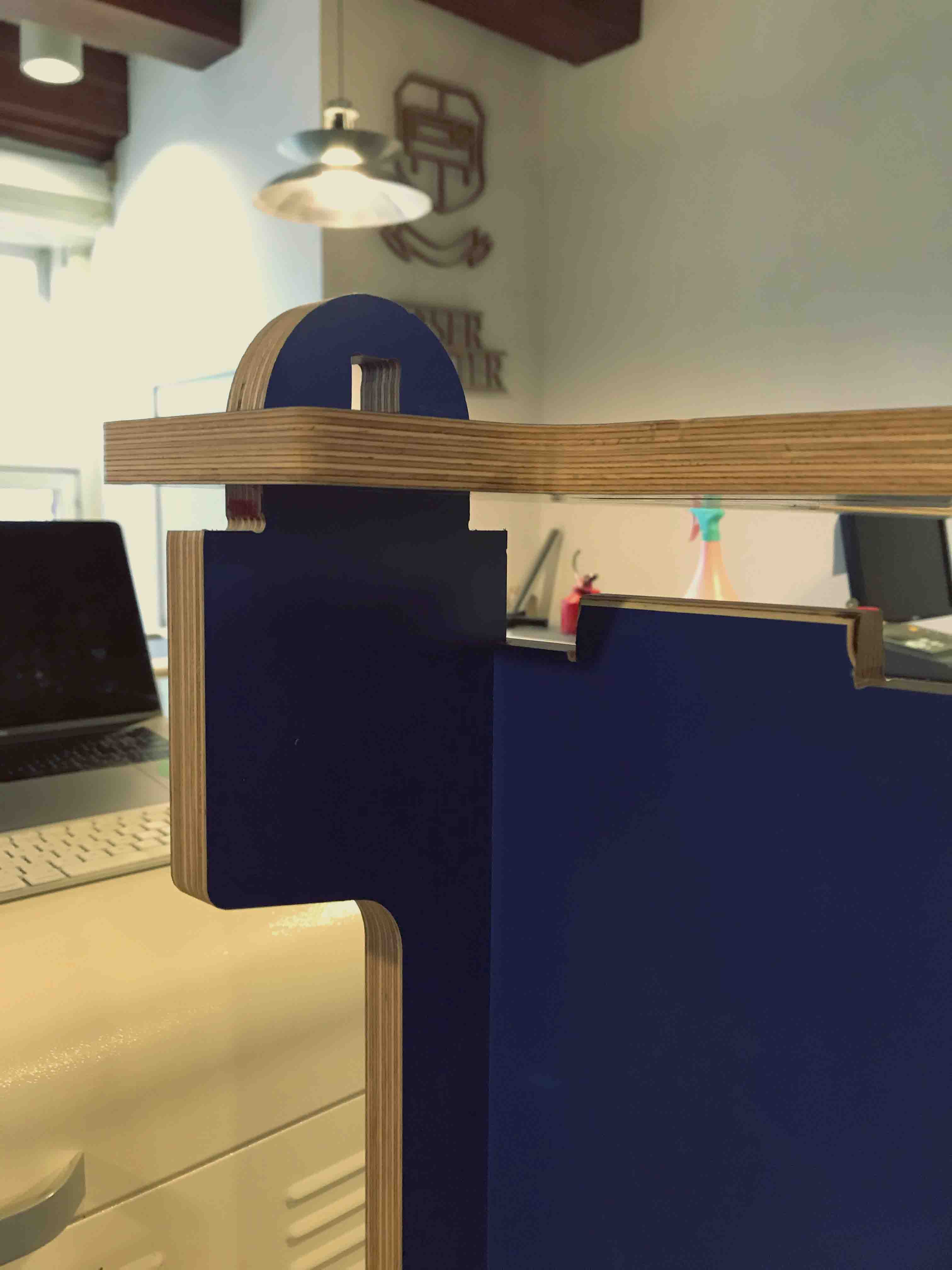
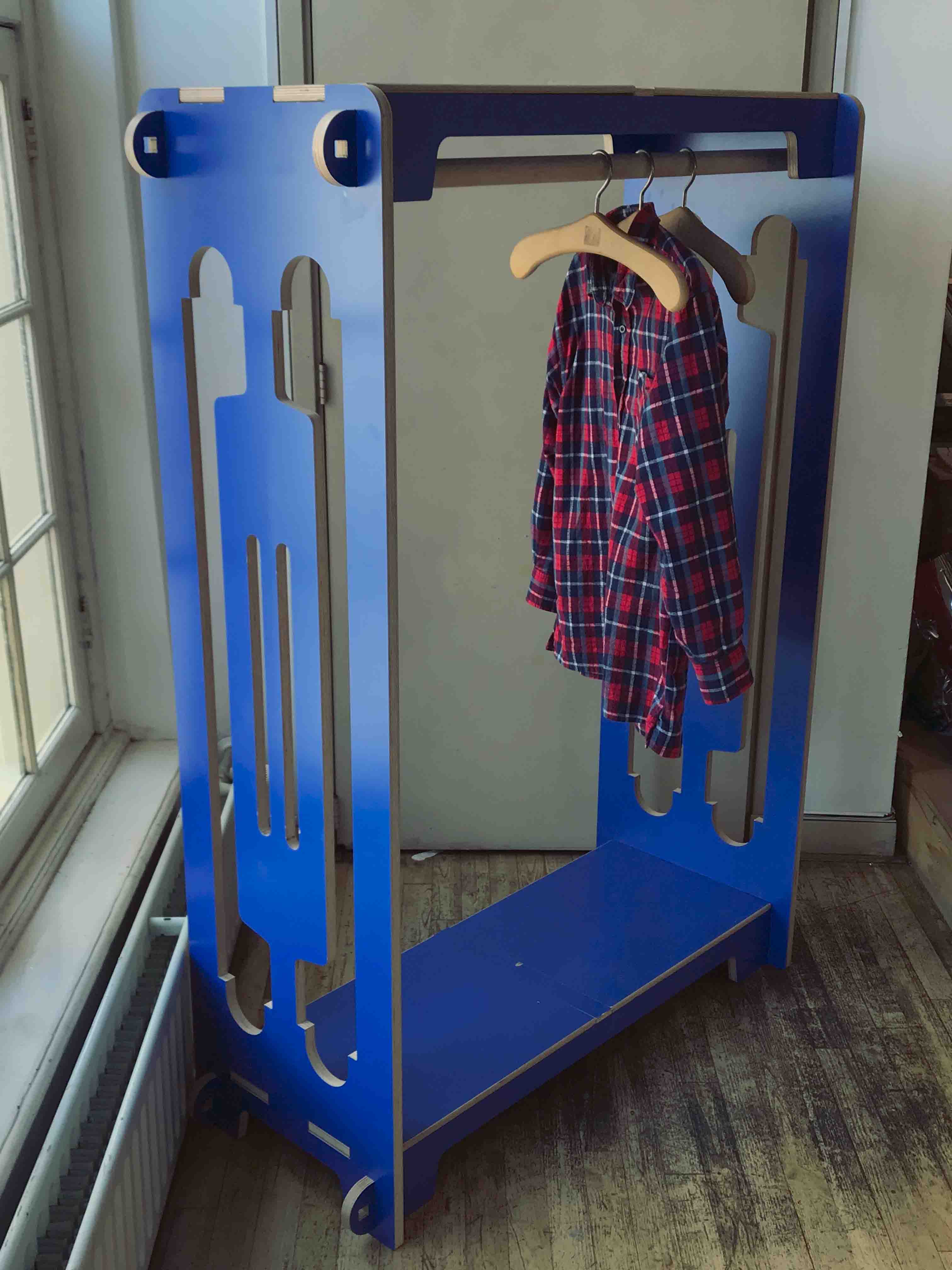
The day before the lecture our coatrack came off the wall. Since I live in a monument I am not allowed to drill anything into the wall. Therefore I decided to make a standing coat rack. The material I chose is a really nice multiplex that is already coated with a bright blue finish. Biggest contraint was to make a big coat rack from a single sheet.
To safe some space I decided to mill some parts and use them as negative spaces in the sides. The support beams for the top and bottom shelves are taken from the sides.
I drew my drawing in Illustrator and used different colours for the different parts. I drew the offsets for the spacers and deviders to get a sense of what the negative space would look like. I made different layers for the different operations (inside toolpath, outside toolpath, pockets...).
Design step by step
- Create an artboard the size of the stock material 1200x2400 mm.
- Draw a rectangle that is 20mm smaller all around, this space is needed to mount the material to the bed later.
- I didn't make any sketches but the goal is to make optimal use of material and keeping a little left over that allows for press fit testing. I decided the minimum height and depth of the cabinet. With this I drew the top, bottom, left and right side. The width of the cabinet is arbitrary, I just made it as big as possible.
- I drew some rectangles for the press fit parts and used boolean union to add or subtract them to the design.
- Since the cabinet doesn't have a real front or back I made some 'spacers' the top and bottom can rest on this and it will also help with the sturdiness. The spacers are milled from the sides, this makes for nice decorative open holes and less waste material.
- In the left side I drew holes for the spacers to fit through.
- For the top and bottom shelve I drew a small pocket to have them slide in place.
- When I was done changing dimensions I finished the drawing for one of the shelves and sides and copy pasted them with 20mm inbetween.
- I saved my design as a .dxf.
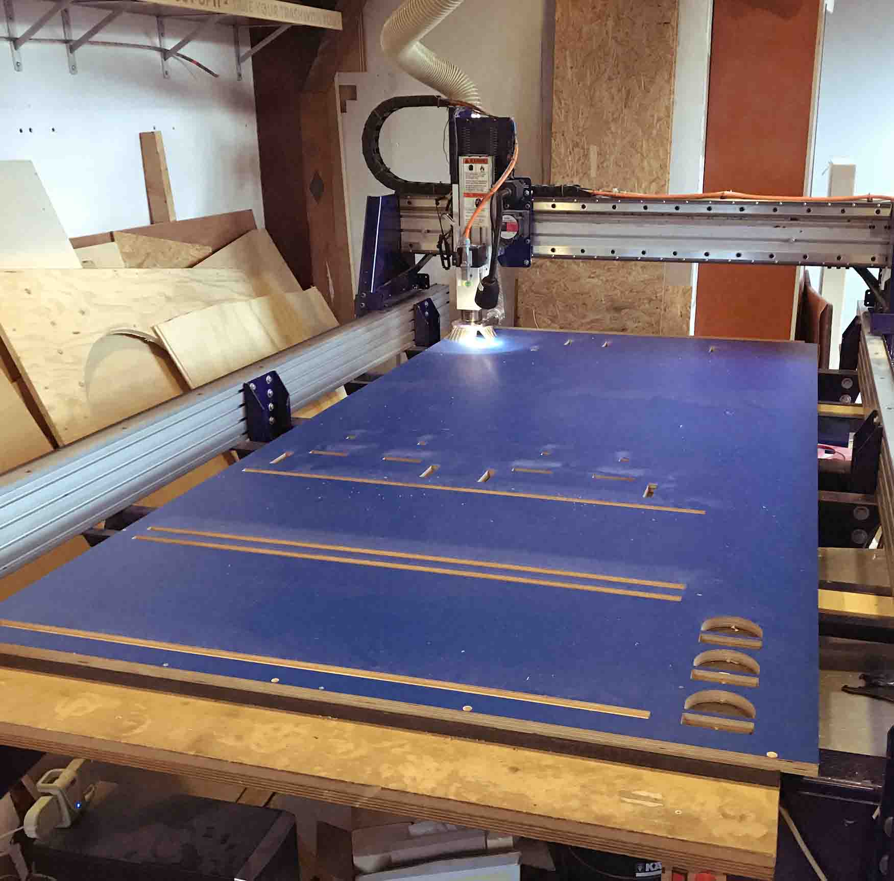
I started my milling job by making the test pieces. I added offsets and used the same speeds and feeds for my final design. The material is quite hard so the speeds were super slow and it took about 6 hours in total to mill. When it was finished I put everything together and nothing seemed to fit.
- the holes for the spacers were too small.
- the teeth of the shelves (top and bottom) were too small.
- Connecting sticks didn't fit.
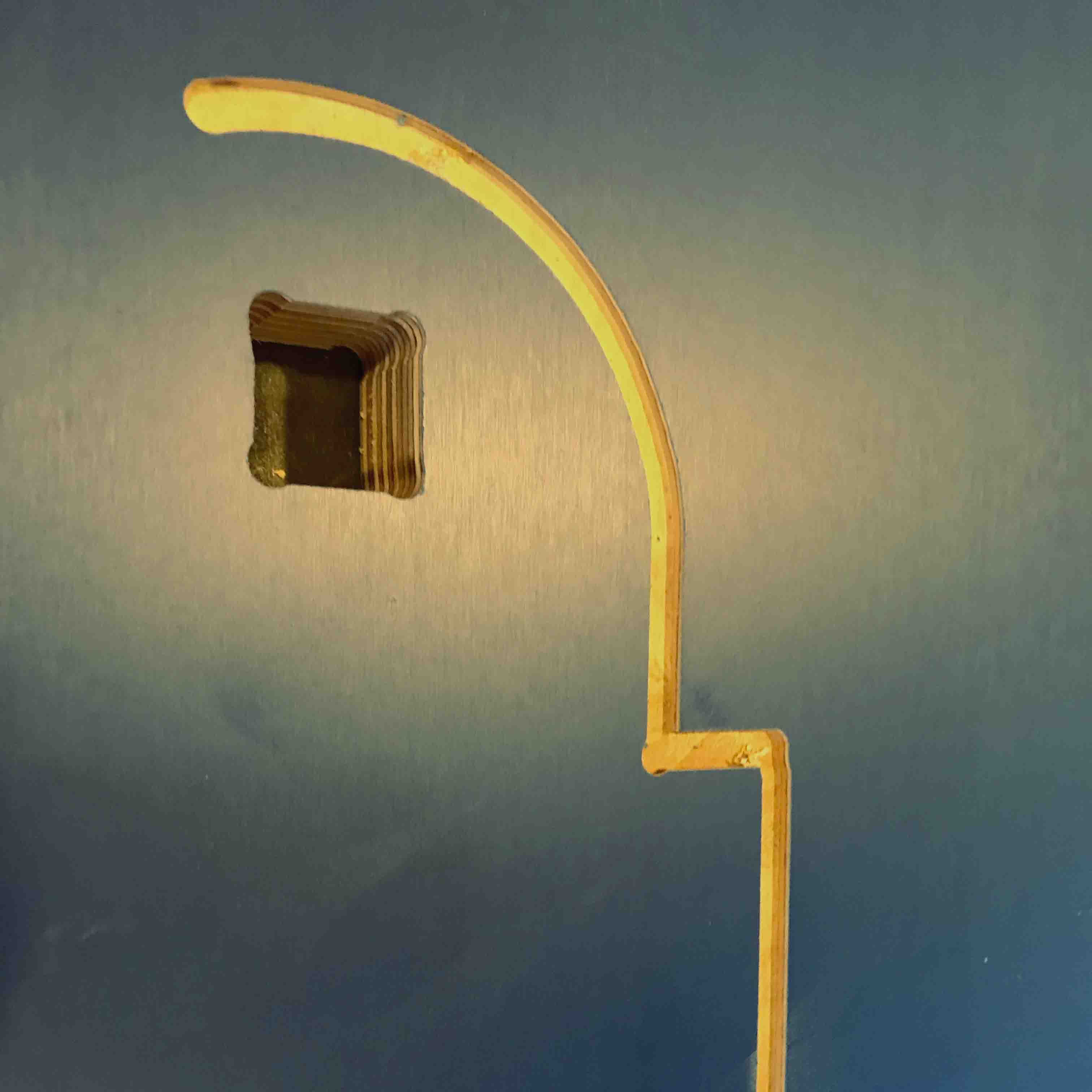
- square holes were not square.
- the shelves were too short.
Also the tabs were really difficult to remove without chipping the material. It is super important to have a sharp chisel at hand - not a typical thing to find outside of a woodworkshop.
After a lot of sanding things started to fit together except for the shelves. I made a mistake in my drawing. I cut the shelves in half and remilled extra pieces to make the shelves a bit longer.
The square holes and the teeth not fitting correctly were issues from the backlash in the shopbot (I think). Since the backlash on the x and y axis is different this cannot really be fixed. This is really a shame since these couldn't be fixed in a way that looks good.
