Final project
On this page I describe the process that has led to the final project. The first concept is described in the first week of Fabacademy. The goal is to make a mindfullness tool that exploreres using different faculties than sound to change the mood of the user. A pensieve. The pensieve will look like a bowl that can be held. It measures your stress levels and will try to calm you down using a pulsating light, scent and color.
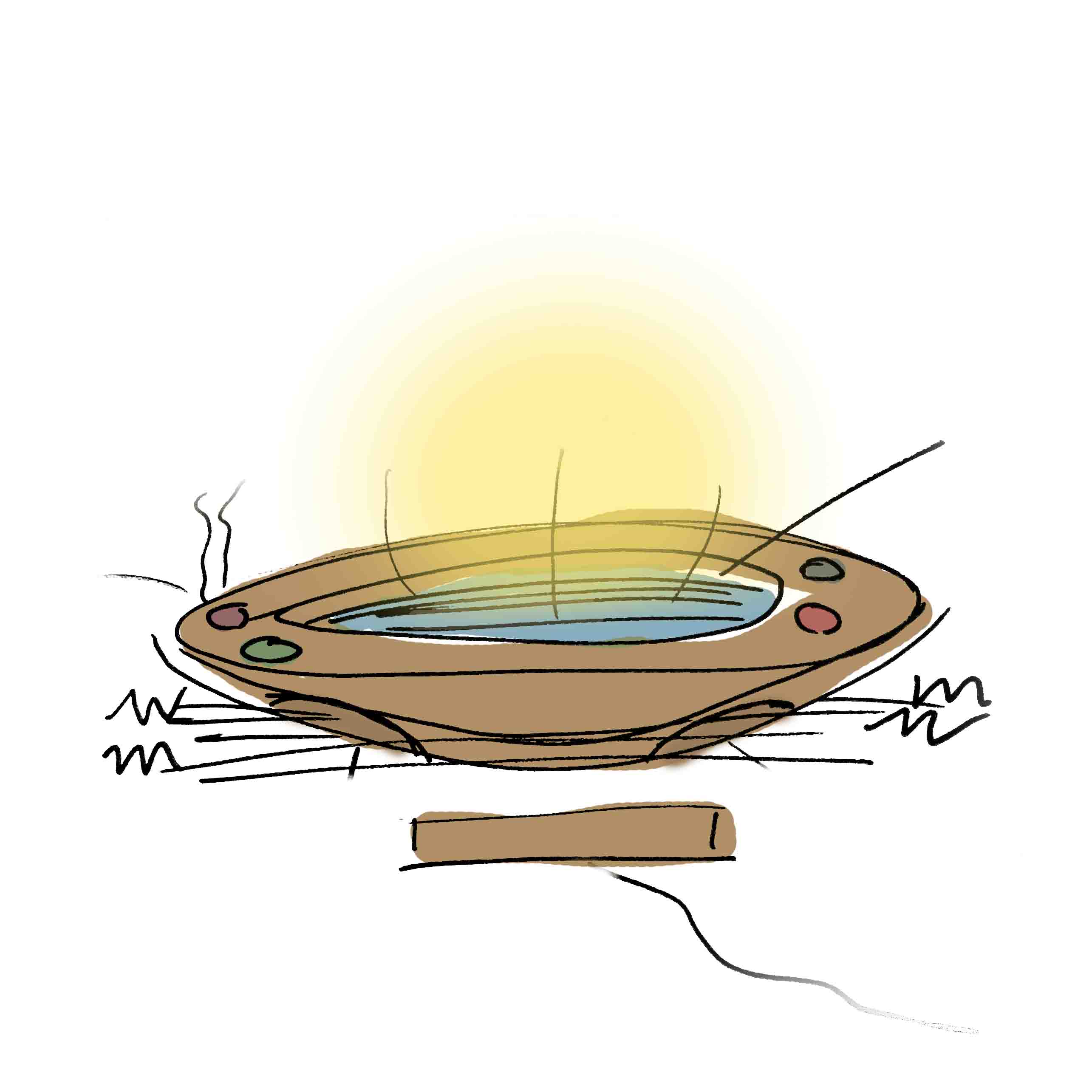
Here you can read what I wrote in the first week about this idea
In the applications and implications week I gave an update of the halfway point of the project development. Including a part list (thus far), a brief overview of work by others and reseach questions.
On this page I will give the most definitive and complete list of findings, decission and processes used. On the final project page I will show a brief overview of the 'final product'.
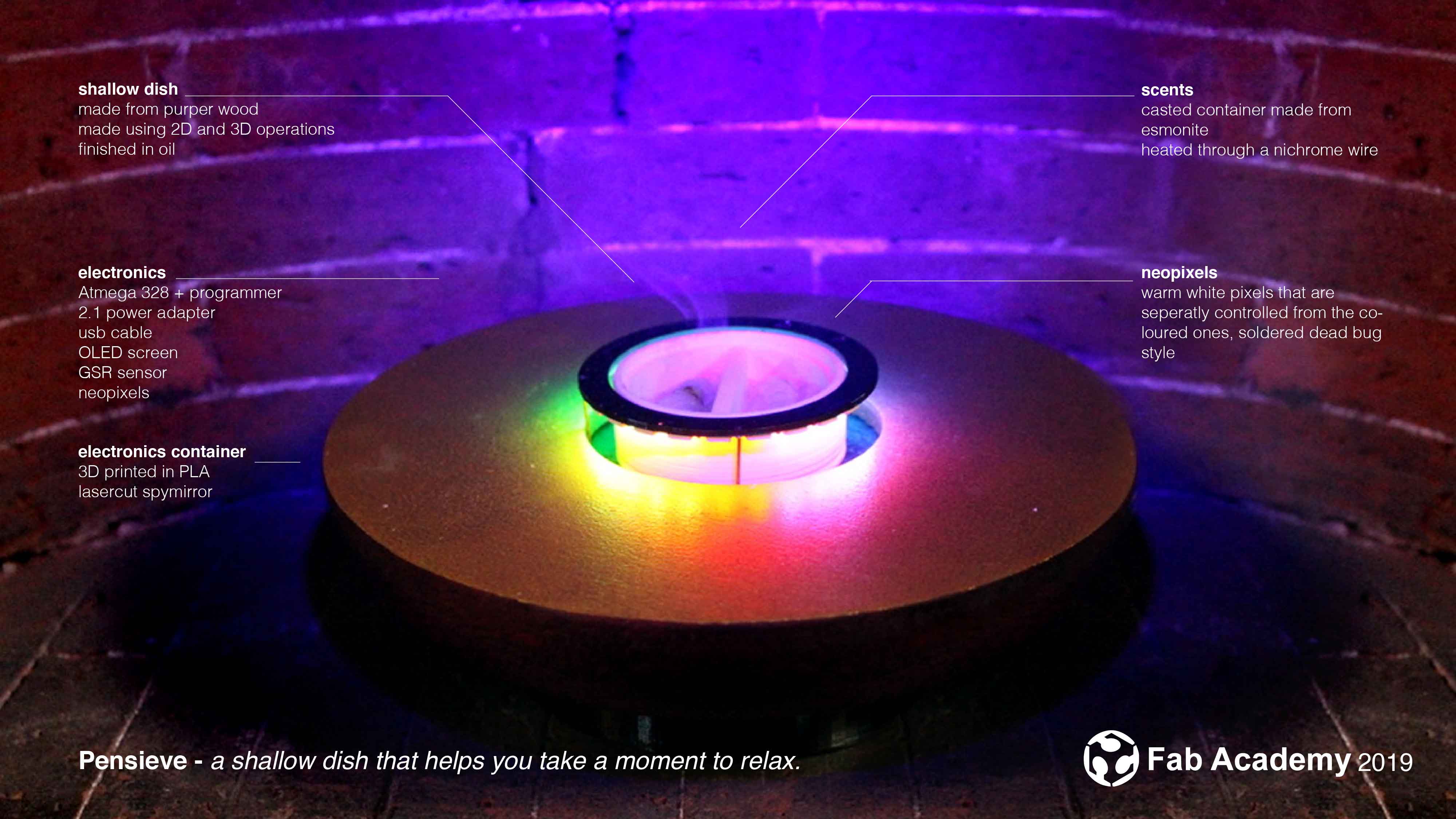
What I wrote in the beginning
"A Pensieve is a wide and shallow dish …The Pensieve is enchanted to recreate memories so that they become re-liveable, taking every detail stored in the subconscious and recreating it faithfully. Even more difficult than the recreation of memories is the use of a Pensieve to examine and sort thoughts and ideas, and very few wizards have the ability to do so."
Challenge I see a lot of people (including myself) being consumed by everything around them. Sometimes it’s nice to get a little bit of help becoming more mindful & zen. There are a lot of meditation high tech tools that can help you achieve this. Most of them are really expensive (brain wave control), funny (headbands) or invasive (apps). There are also a lot of low tech options but those mostly rely on us being in a relaxed space and taking time out of our day (think guided meditation sessions). I want to make a subtle tool that helps us to relax during those moments. Let’s call it the Pensieve.
Solution The Pensieve helps the user to become calmer without relying on sound. By holding the Pensieve the heart rate and/or breathing rate can be measured. This is the “stressed” state of the user. Using different feedback the user can be persuaded into a “calm” state. For example a fast breathing can be slowed down with a light that starts fading in and out at the current breathing speed and than slowly dims to the relaxing breath.
Outputs that can be explored are: movement, colours, scents, visual, textures.
Different shapes can be explored: household objects, bowls, cauldrons, wall mounted objects, chairs. And also think about the possibilities for different contexts and people. For example: kids, elderly, people with hearing impairments, people on the autistic spectrum. Or: in public spaces, in classrooms, at the dentist.
Research has proven that sound works really well for this purpose - there are no examples of devices or research that mirror this principle to other outputs.
Bill of materials
Let's start with all the materials that I used for my final project. I have split things up into materials and electronics. Most of the electronics are part of the standard inventory in the lab but others had to be bought. Some of my materials are scraps that I had lying around so it's hard to put a exact number on it. In total I spend about 60 euros on electronics and materials but if you were to buy all of it it would set you back about 250 euros. This excludes tools and machine time. There are definatly ways to make this project on a budget - I would recommend cheaper LED's, cheaper wood and making the scent container out of a pre-made glass container.Here you can find the bill of materials.
Make or buy
For my LED's I wanted to use SMD RGBW (warm white) leds, these are not standard in the inventory. When I looked for them they were pretty expensive and could only be bought from American suppliers. The cheapest solution was to buy a ring from a local supplier. Since I needed them in a ring anyways I decided to not to remove them from the ring they came in but to make a small modification to my design to accomodate the size of the ring.
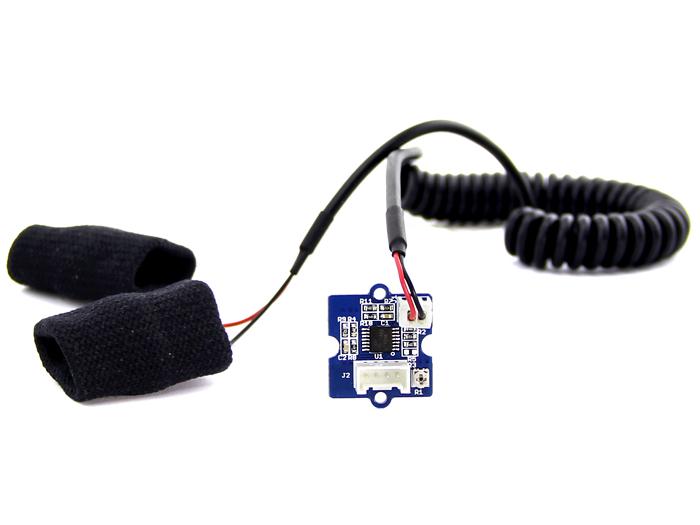
Starting my project I wanted to make my own sensor. I did some research and found a bunch of projects that were either poorly documented or had unreliable results. The best option I found needed a specific amplifier and regulated resitor that were yet again not in the inventory. Therefore I bought a sensor board from Groove to try it out. With a simple sketch it worked out of the box so I decided to stick with it.
Design PCB
Software used
- Kicad
- Adobe Illustrator
There are different parts to the electronics of my board. Firstly my goal was to program my project from the 'outside' of the enclosure using a USB connection. To do this I added a Satshakit (bottom left of schematic) directly linked with to a FabIsp (top left side of schematic). The linking is pretty straightforward, you put both essential bare bones boards in a schematic and link the ISP header pins from the FABISP to the Satshakit corresponding pins.
Also note that both boards normally come with two LED's, I removed the LEDS's (and their resistors) from the FabISP since they indicate power and programming (just like the ones on the Satshakit).
The next challenge was to make the board fairly small so I removed all header pins. Next I added back the essential ones starting with a FTDI header that is now easily connectable compared to the original kit where all pins are scatered around the board. Also I added a VCC and GND connection to allow for an external power source.
Following were the imporant elements to my final project, like the SMOKE connectors I made and tested in the Output week, the I2C OLED screen I learned about during Networking week, the NEO pixel ring and the GSR ring.
SMOKE
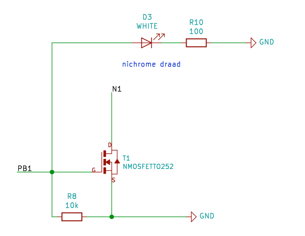
To create smoke I use a NCH Mosfet that is connected with the gate to PWM port. The drain gets connected to the ground trough a nichrome wire that will heat up to create smoke. The data pin is also connected to the source with a 10K pull down resistor inbetween. For prototyping purposes I added an LED that will light up if the port is active. This element excists 3 times on the board, this can create three independantly programmable hot wires.
I2C OLED
The OLED screen is pretty straightforward since it used I2C for communication. It needs VCC, GND, SCL and SDA for it's communication to the board. SCL and SDA can only be connected to pin 28 and 27 on the ATMEGA. Since the connection is pretty short no additinal resistors are needed. Keep in mind the courtyard space that the OLED will need. I didn't do this good enough in my design therefore it was a bit akwardly positioned.

NEOpixel ring
The Neopixel ring I needs only three connections VCC, GND and DATA in. The data pin needs can best be connected through a 470 ohms resistor to the ATMEGA, this prevents spikes on the data line. Adafruit has a good resource on this, the Neopixel überguide. Also a 1000 uf capacitor is added between the VCC and GND to help prevent the initial onrush of current from the DC power supply that could potentially damage the pixels.

GSR sensor
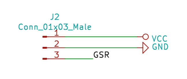
The GSR sensor comes with a Groove connection, it needs only 3 out of four pins (VCC, GND and and SIG). The SIG needs to be connected to a analog pin. Since it is a board no additional parts or components are needed.
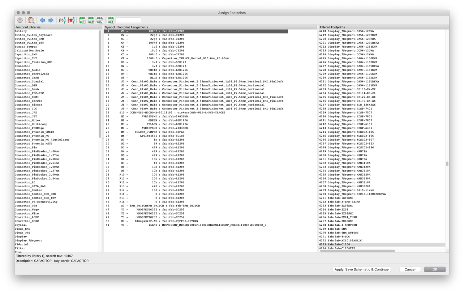
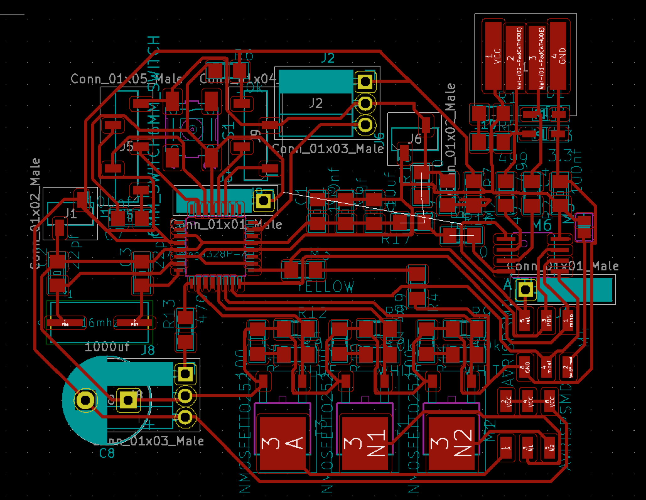
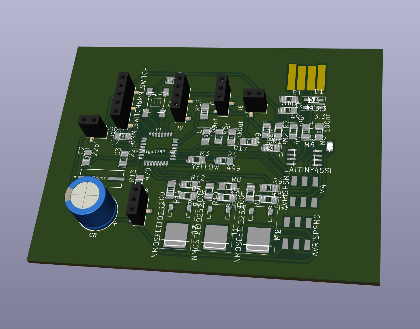
For the tracing I used the design rules from the electronics design week. I organised them as closely together as I could. Also I tried to group components together that have similar functionality (Mosfets). Since I want to have my OLED screen above the board and I have limited space in my project I tried (and failed a bit) to envision courtspace of the board. Higher components are the 1000 uf capacitor and the header pins. Some of the header pins (GSR sensor and Neo Pixel ring) were made through hole since this is the components will live on the other side of the board anyways. The reset pin was a bit difficult to connect and instead of needing 6 resistors I wired it through the back using two single holes.
Fabrication PCB
After the tracing I exported my design to SVG and imported it into Illustrator to add my name and project name to the board and create a circular outline. I saved two seperate files as a PNG - first one are the traces and the second one the ouline with the holes.
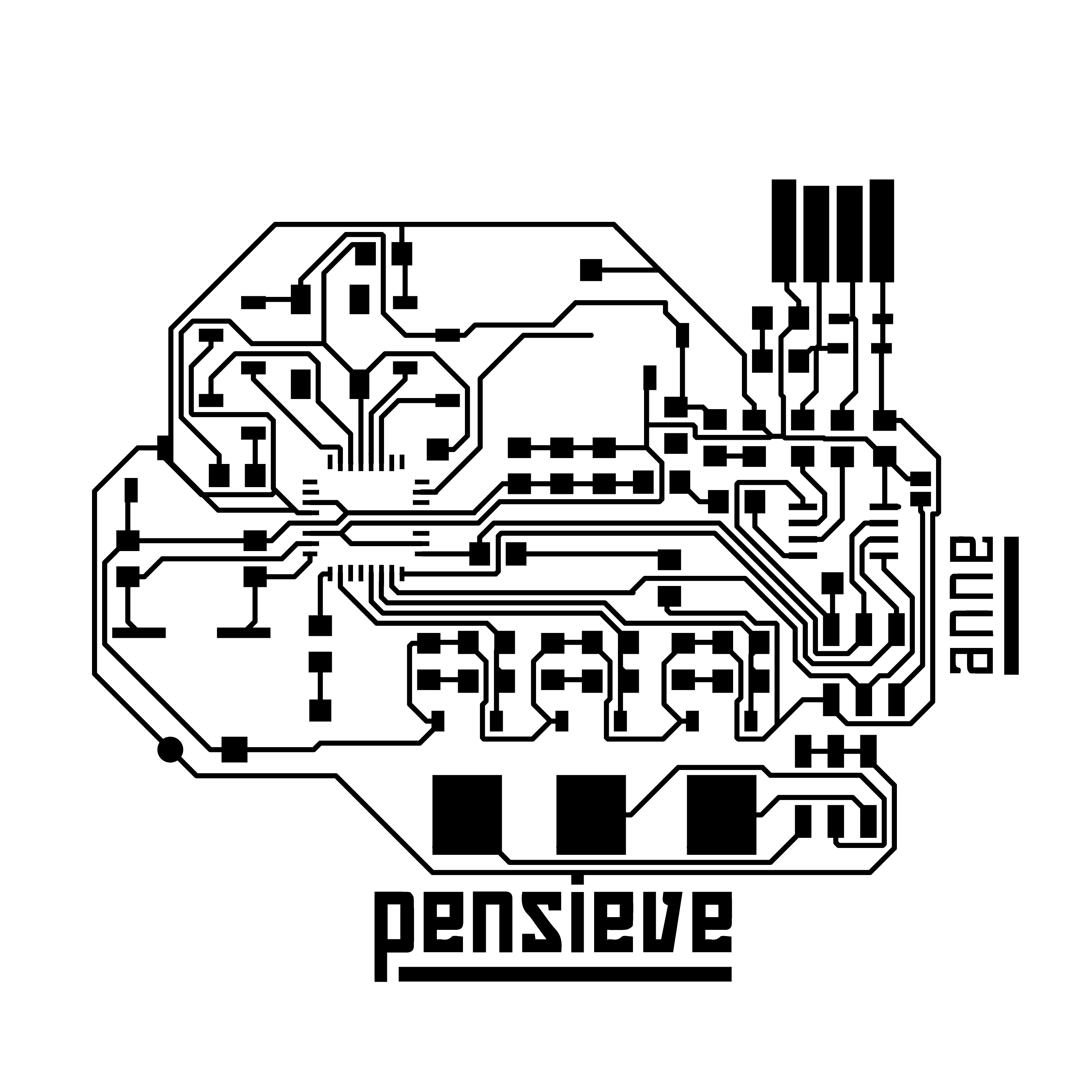
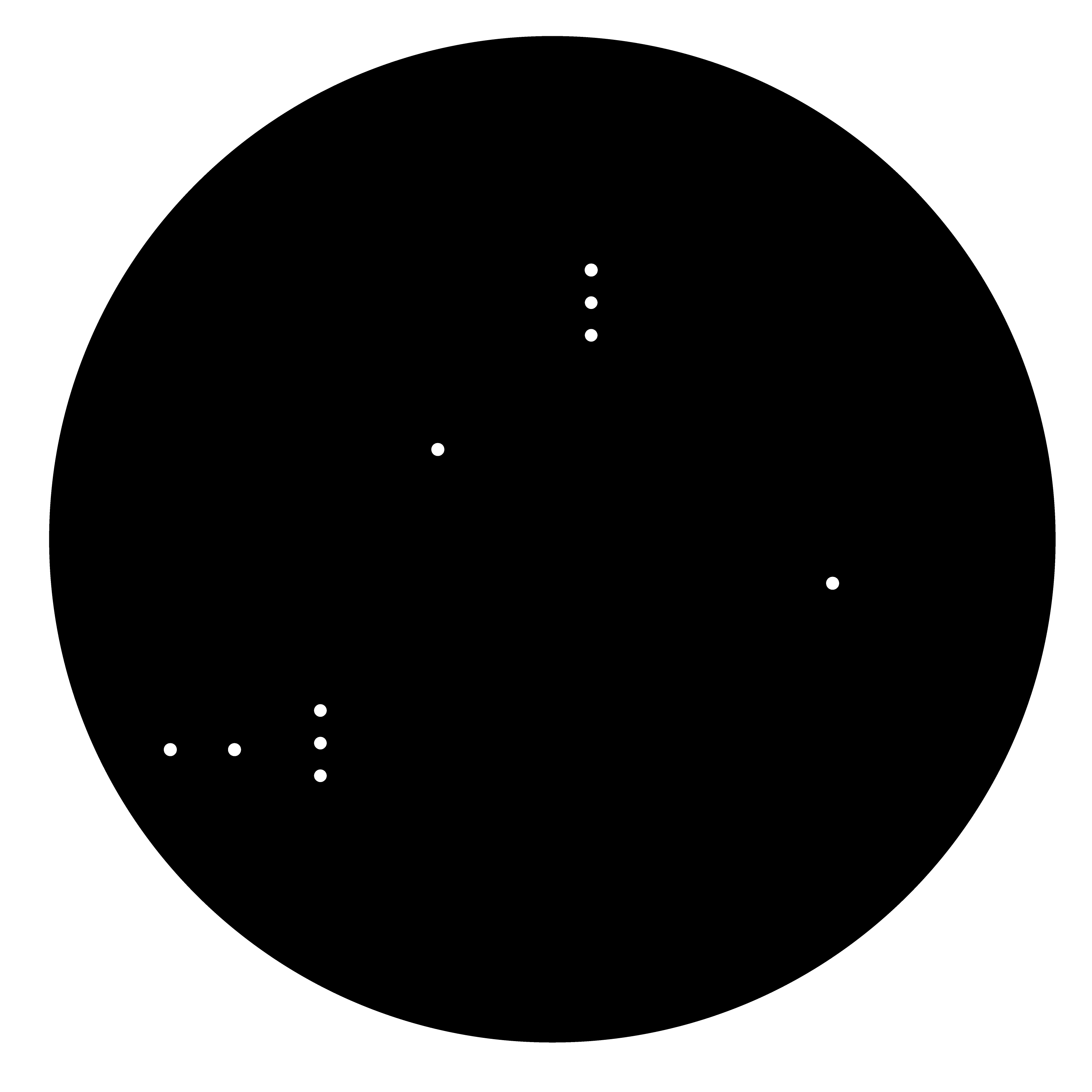
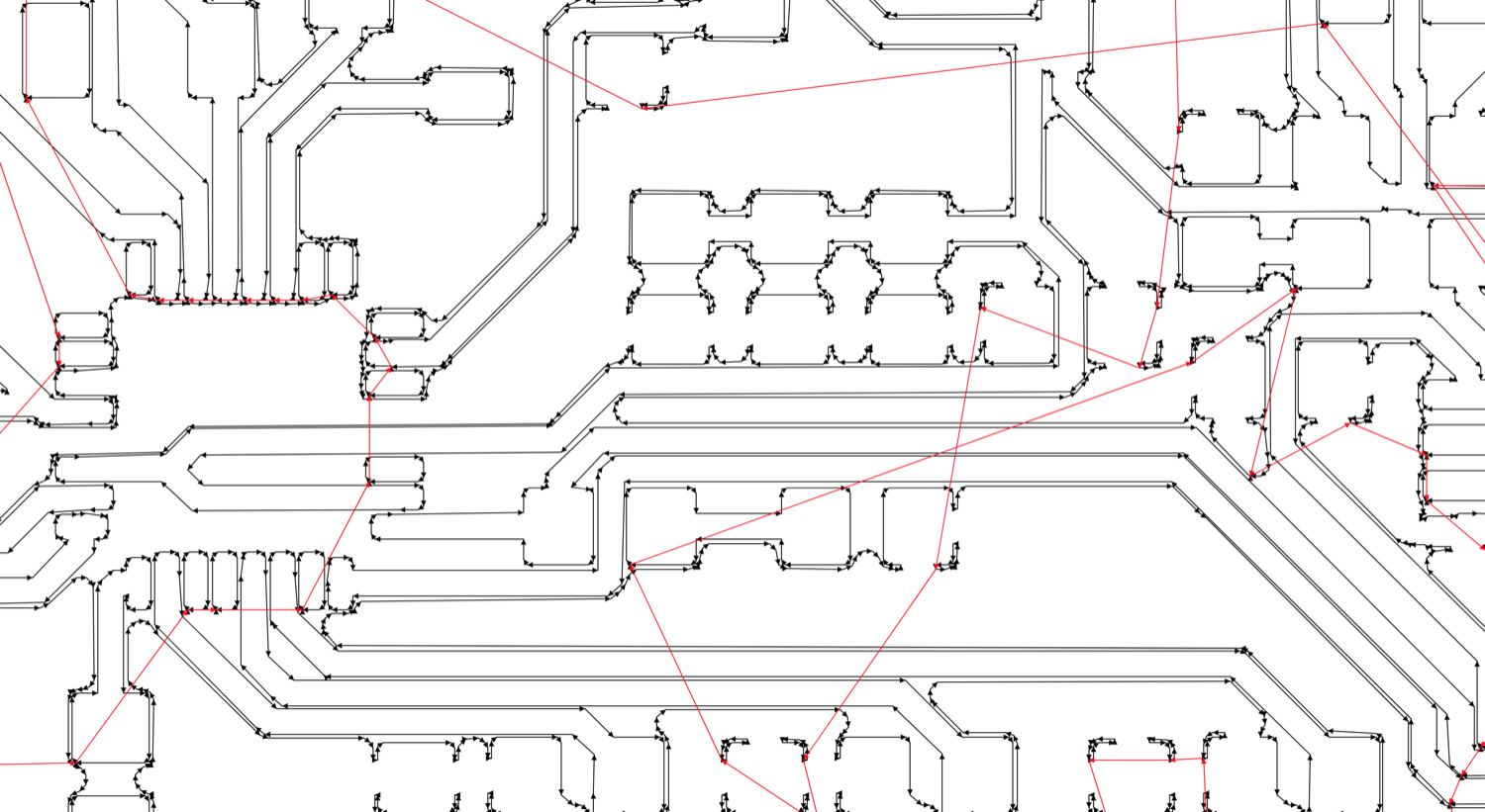
After setting up the machine, this is described in electronics production week, I imported my first PNG into mods. I had a few breaking milling bits but otherwise the the traces went fine. For the outline I changed the milling bit and had to re-calculate a few times to make sure the holes were cutting on the inside. Somehow mods can have differences between calculating. Just keep an eye on the pads of the Atmega to see if they are being seperated.
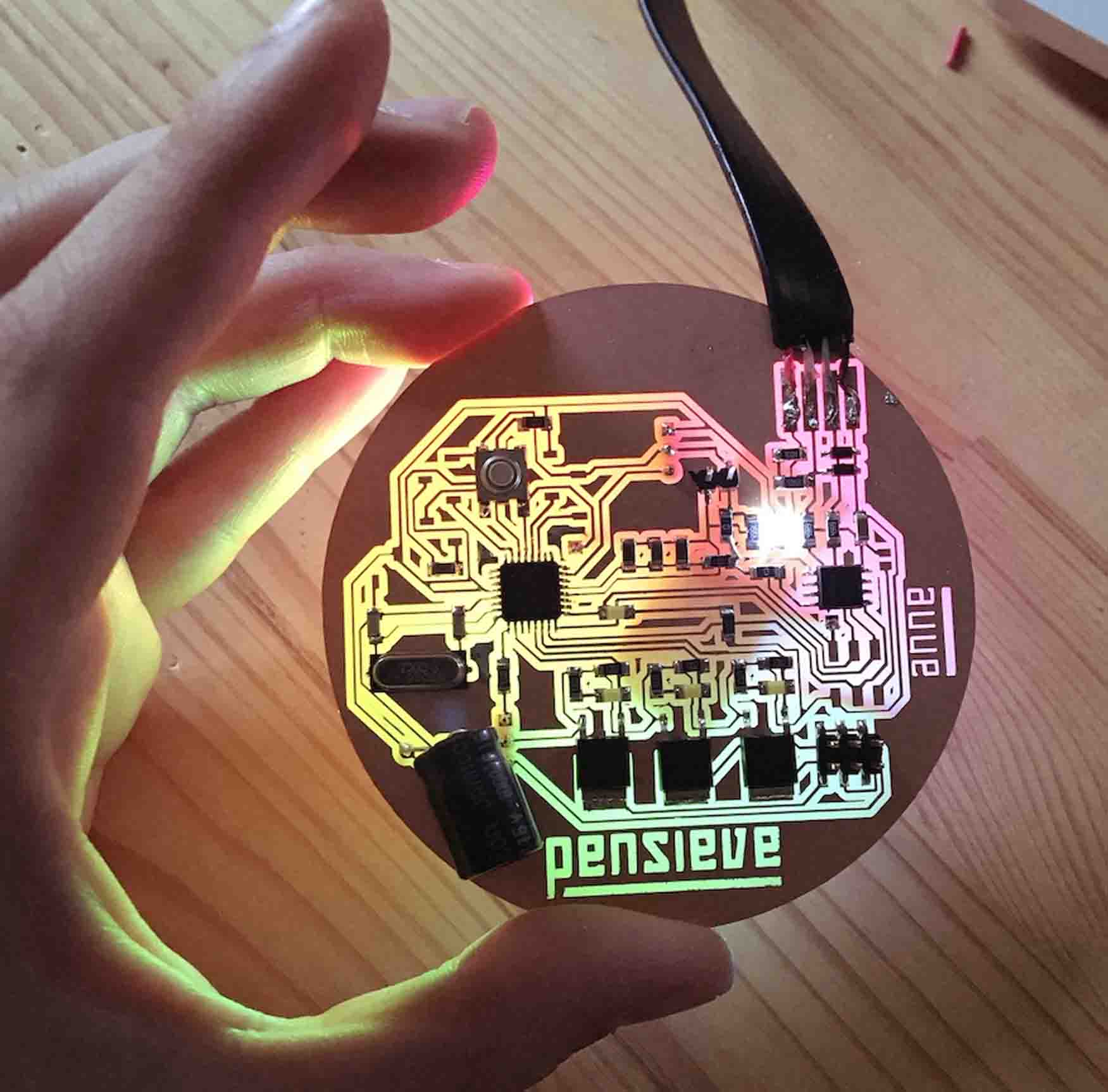
Soldering is a bit tricky for this board since everything is pretty close together. I left of some parts that were only essential for debugging purposes like the FTDI header and ISP header to program the ATTINY (I recycled an old chip with a preloaded bootloader). I started with the chips, moved on to all parts for the FABISP and checked if the fabisp was working properly. Than I moved on to all essential parts for the Satshakit and tried uploading the bootloader. Once the bootloader was on I added all essential top mounted parts going from low to high (resistors, capacitors, I2C screen header, VCC/GND pins, etc) and than the bottem mounted parts.
Programming
I wrote a couple of different test codes to get all seperate parts to work. In the Output week I wrote a code to test a pulse width modulation program for the mosfet. Next I wrote a code to display a bitmap on the OLED. Than I tried the test code from the GSR sensor from the Groove wiki page and combined it with the OLED (I2C, learned in networking week) to generate a live graph. Since I had some experience with Neopixels I tried the neopixels with the Strandtest RGBW program that comes with the Neopixel library. Also I combined the fading of the neopixels with the GSR sensor. When I knew all the seperate elements worked I took a deep breath and panicked on where to start with the programming.
When it was time to combine everything I split things up in different tasks.
Task 1:
When the pensieve switches on it should do a start up protocol.
Program: Neopixels should do a light sequence and the OLED screen should display a bitmap. The bitmap get's stored in the EEPROM memory.
Taks 2:
When the pensieves sensors don't register anything it should be in resting mode.
Program: Resting mode is when the Neopixels warm white LEDS are on and the OLED screens shows the message for the user on what to do.
Task 3:
When the pensieves sensors are touched it responds by starting the 'moment'.
Program: Beginning of the moment are a X amount of breahing paced warm white pulses. In the middle the pulses go away and make way for a color sequence combined with smells for a X amount of time. It ends with a X amount of breaths.
Task 4:
When the sensors are put on the pensieve uses the data to prepare a custom moment depending on the stress levels.
Program: The OLED displays the current stress levels and all the X's from task 3 are calculated.
For the programming I got most of it done myself using all the examples I made and found in the begining. I ran in some trouble to get all the calculations working since the Neopixels and OLED are both quite depending on timing. To solve this I used a Elapsed millis libary and wrote an alogritm that calculates all values for the Neopixels and OLED before pushing them instead of looping it all the time.
During the programming I worked mostly on a normal Arduino board since it's a bit more robust than my PCB. When the script was finished I upladed it to my own PCB wich worked fantasticcally. The only difference being that a onboard programmer is used to upload the sketch, in praxis this means to press shift when uploading.
Design
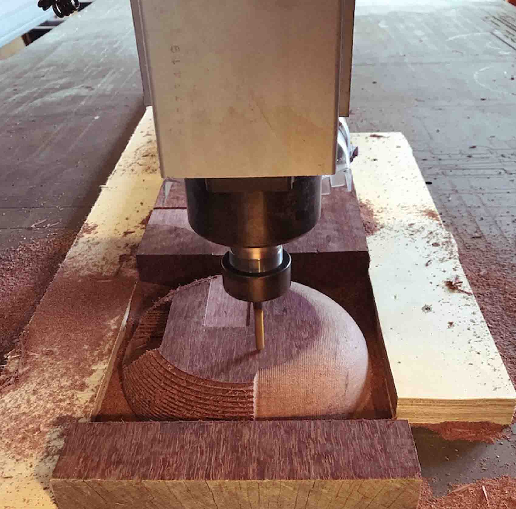
When I started the design process I couldn't quite wrap my mind around how everything would look and work together. So I decided to break things up and just start building. I decided to start with the wooden bowl shape since - the size was dictated by the material I had at hand and the size of the electronics that had to be on the inside. I milled this before continueing to design anything else. The little nook on the side is where the electronics get connected to the outside world. Since this is in a akward position to mill I made a hole by hand and 3D designed and printed a cap for this. Than I moved on to the 3D printed cylinder that would hold all electronics and interactive parts. And I ended with a simple circular mirror cut.
2D Design
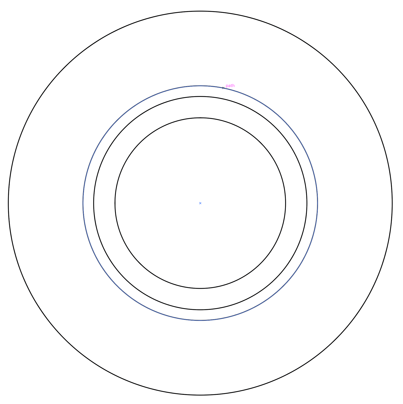
Their are two different parts of the pensieve in 2D, the mirror on the bottom and the cylinder through the wooden bowl. I tried to make the mirror as large as possible, without being larger than the inside of the electronics compartment. The negative space, let's call it electronics compartment, is a 2D shape that can be milled in 2D or 3D. I decided to draw this in 2D since the shopbot 3D passes don't allow for a circular direction, only 'scanning'. This means that if I wanted a hollow cylinder using 3D operations it wouldn't be as perfectly circular as when I would do it in 2D. Also it is much faster to do it in 2D since the motion fits the shape instead of 'scanning over it'.
So I carefully measured and drew a bunch of circles in Illustrator for the milling and lasercutting. For the lasercutter I exported it as a DXF and for the milling machine I exported it asn an .AI CS2 Illustrator file.
3D
For the 3D design parts I was happy to show off a little bit more of my skills although this is also simple but very effective. There are a few parts that I designed in 3D - firstly the wooden bowl for milling, secondly the inner cylinder for 3D printing and thirthly the mold for the little bowl on the top where the smoke will come from. All 3D shapes were designed in Fusion 360.
Wooden bowl shape The wooden bowl is drawn on the YZ plane in Fusion and than revolved around the center axis. The little open nook on the side is a 2D extrusion that cuts into the shape.
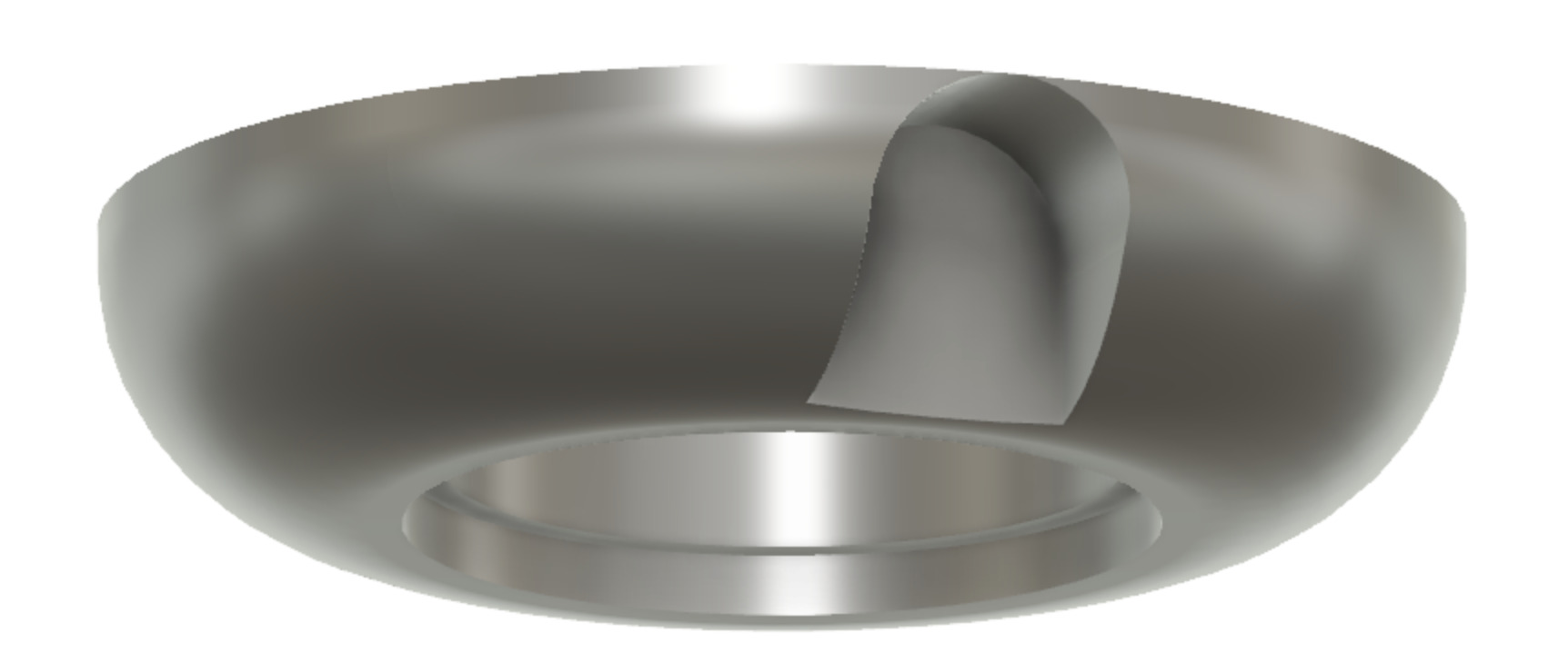
Inner cylinder The inner cylinder is a 3D printed shape that I drew in a seperate file to keep things a bit organised. It's drawn similarly to the bowl shape. On top of the inner cylinder is a little container for the smoke liquid. Since this part cannot be 3D printed for this application I decided to 3D print the mold. This is done by adding a circular wall and thin floor to the part so I can poor the mold rubber in directly.

Fabrication
For the fabrication of my board I used appropriate addative and subtractive machining operations. I used milling, 3D printing, lasercutting and molding and casting to fabricate my final piece. The wooden bowl is milled in both 2D and 3D, the inner cylinder is 3D printed, the mirror is lasercut and for the container on top I made a mold.
Lasercutter
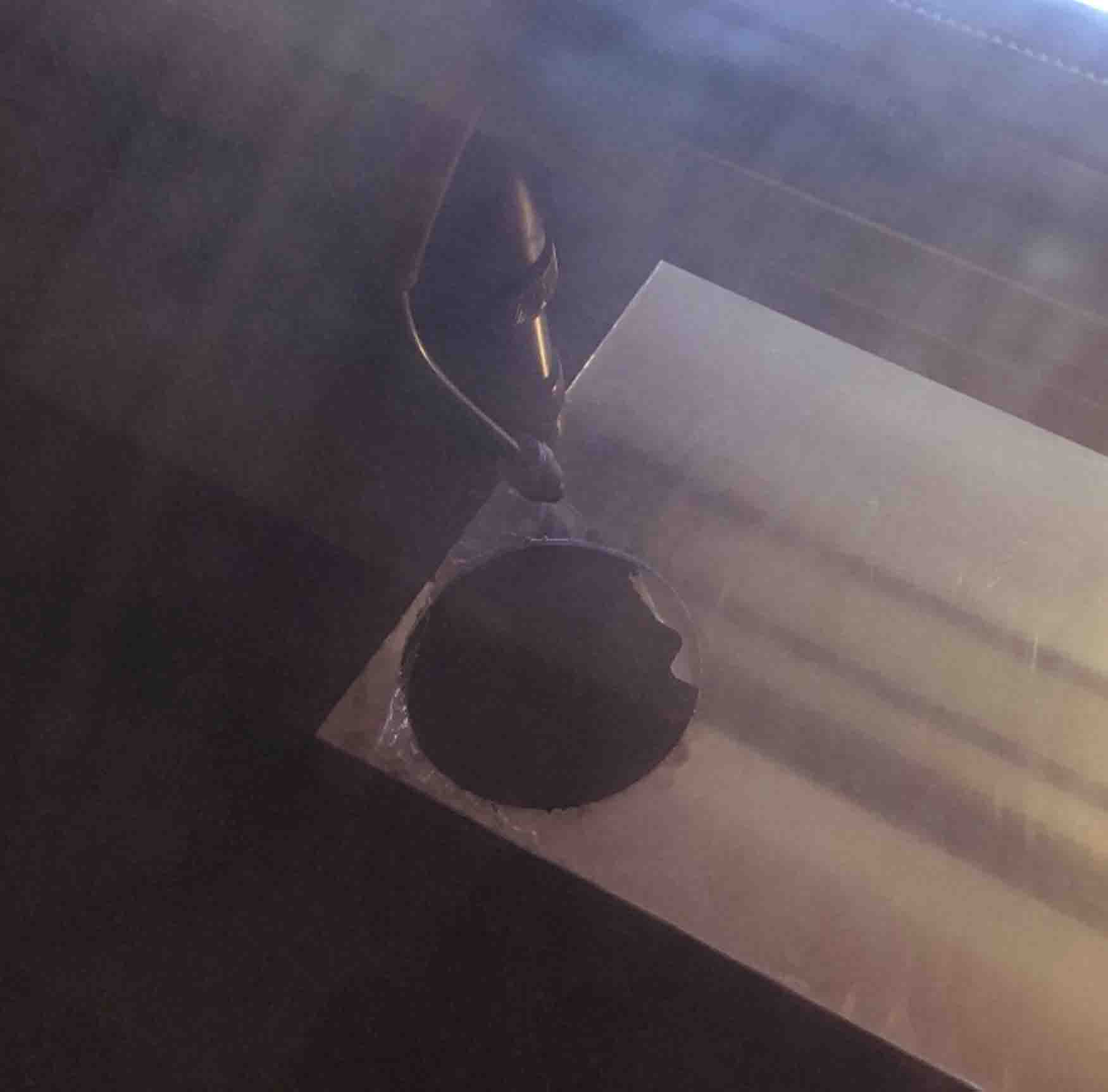
The little spy glass mirror on the bottom is lasercut. I wanted to choose a material that still allows some transparancy and has a nice finish, acrylic. The easiest way to cut a circle from acrylic is using a lasercutter - it leaves a nice finish and is a super quick job. For the cutting I left on the protective layer on both sides and used some scrap pieces to lift the material a little bit up from the metal bed. Where the laserbeam hits the metal a small imperfection apears on the acrylic. This is incredibly vissible with spy mirror.
Machine: BRM Lasercutter
Material: 3mm spy mirror
Settings: 30 speed / 80 power
3D printing
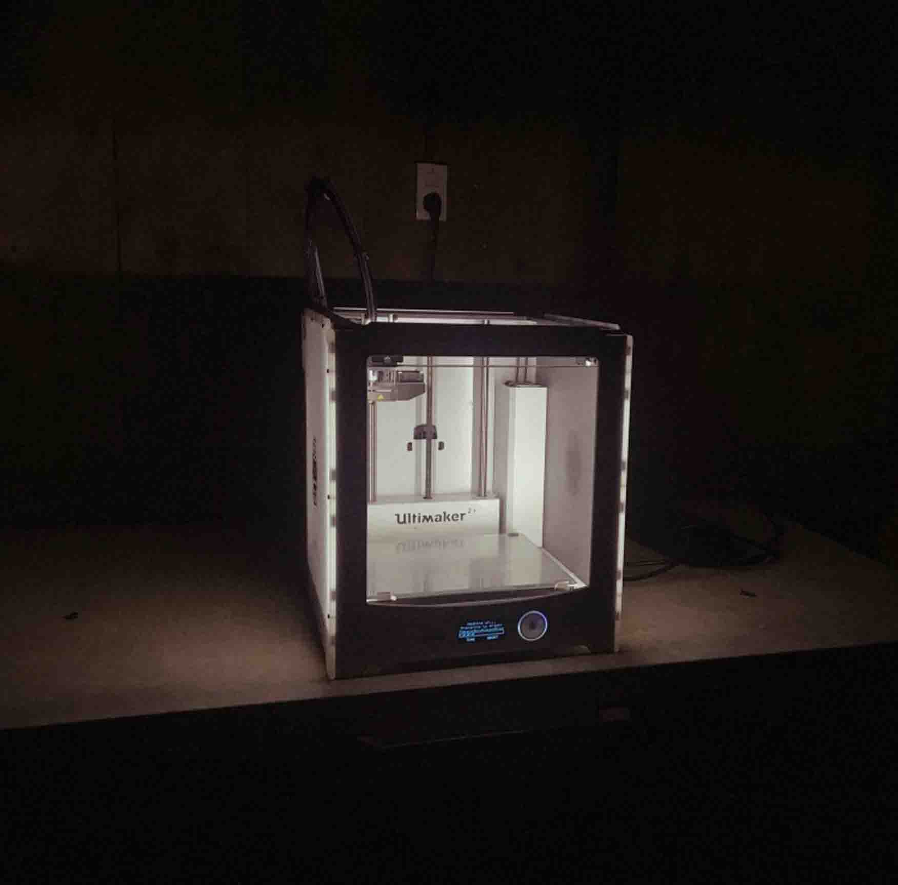
For the inner cylinder I needed a way to keep in all the electronics and have them accesible. The cylinder moves in and out and has a shape that would be difficult to fabricate in a different way. Since the walls are pretty steep and thin and have little nooks. For the material I chose PLA since that was on hand and has good enough properties for this application. I chose relative quick settings with a larger layer height since the part is mostly not vissible. Since the part has a large, thin and flat surface area I chose a relatively high bed temprature to minimize wrapping.
Machine: Ultimaker 2+
Material: Ultimaker PLA black
Settings: layer height 0.15mm, infill 15%, nozzle temp 220 degrees, bed temp 60 degrees
Wood milling
The outer part of the enclosure is made from wood. I chose a scrap piece of material, purper heart. The grain is very even and dense, this makes it pretty easy to mill. Since I was limited to the stock I had I decided to stick it to the bed with double sided tape and some scrap wood supports, this allowed me to make the most efficient use of the material. I started with a 3D roughing job, did a finishing toolpath and ended with a 2D toolpath. For the milling bits I chose bits with enough cutting length, 2 flutes for the roughing and 2D operation and 4 flutes with ballnose for the finishing. For the finishing I did a 15% overlap and only on the X axis.
Machine: Shopbot
Material: Purper heart
Milling bits: 1/4 inch ballnose 4 flutes & 6mm end mill
Molding & casting
For molding and casting I ran out of time to make a super nice mold out of millable wax. So I settled on making a 3D printed mold. Since the 3D printer needs less babysitting this was very time effective. The only downside is that it looks a bit less finished. Fortunatly it's unnoticable in the finished product since it's mostly hidden. After printing the mold I sprayed it with Universal mold release and casted it with Vytaflex 50. A day later I got the Vytaflex out. I didn't use any angles in my design to make the release easier but it worked perfectly fine, the PLA mold walls did not survive since they were only 0.4mm thick, this was to be expected. Than I poored in the Acrycast, a nice composite material made from plaster and acrylic. This makes it both waterproof and resistant to very high tempratures, perfect for my application.
Machine: Ultimaker 2+
Material: PLA, Vytaflex and Acrycast
Mixing ratio Vytaflex: 1A:1B by weight, cure time 16 hrs
Mixing ratio Acrycast: 1A:2.5B by weight, cure time 30 min
Assembly & finishing
First part of finishing the wood was to give it a light sand (80, 120 and 240 grit) to get rid of most of the step over lines. Than I put it in wood oil and polished it up with a 800 polishing pad the next day. Than I did a second coat and repeated the polishing. The top of the wood is painted in gold in two layers. The prints needed little to no finishing, just some minor webs that were easy to remove.
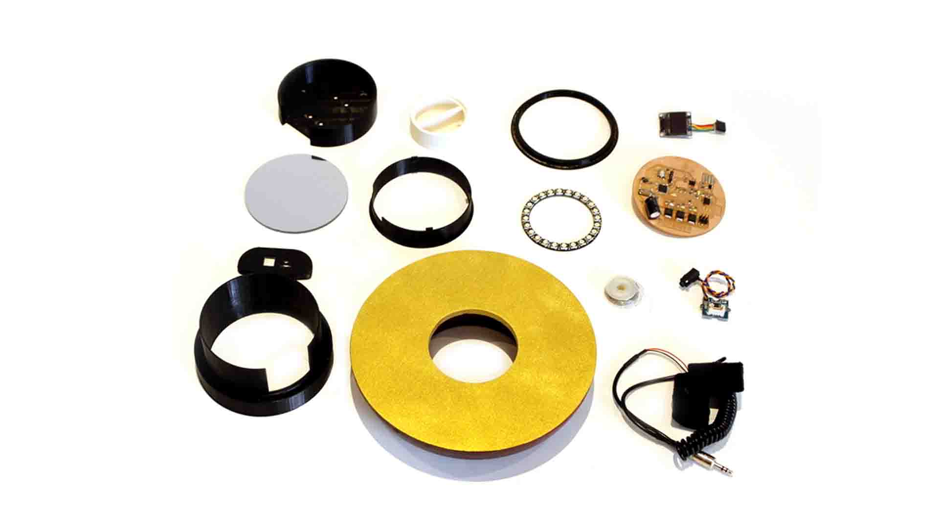
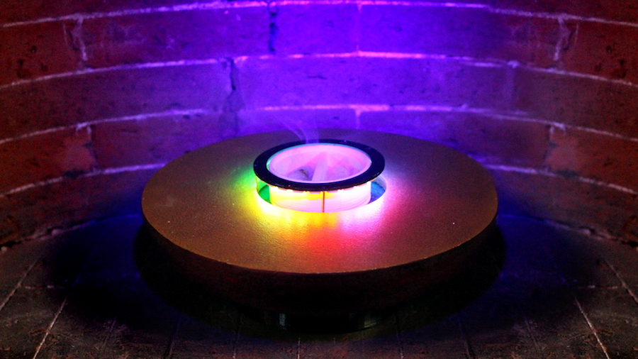
With all the seperate parts and PCB in hand it was time to assemble. I started by assembling the top cap of the cylinder where the Neopixels are mounted together with the container where the smoke comes from. The acrycast container is mounted with a drop of hot glue and the neopixels using brass rods that double as their connection to the PCB. The wires for the smoke go directly to the PCB through the cap and container, so the wires are invisible too. Next I connected them to the PCB keeping an eye on how it would fit together. I put the cap inside the wooden enclosure and also wired the power adapter, usb cable and plug for the gsr electrodes. Than I added another ring for the PCB with the OLED on top. I finished by carefully pushing the outer cylinder to close everything off. Key here is to be super carefull since it is a pretty tight fit!
Files
All files are in a single folder. I split it up into three categories, electronics, enclosure and programming. For each categorie there is a editable folder and final folder. I have also added some recources that I used and the BOM.
Download all files here
License
Design enclosure - You can, change and continue to develop this design and share under a compatible license. Not for commercial use.

This work is licensed under a Creative Commons Attribution-NonCommercial-ShareAlike 4.0 International License.
Software - You can use, change and continue to develop this design and share under a compatible license. Not for commercial use.

This work is licensed under a Creative Commons Attribution-NonCommercial-ShareAlike 4.0 International License.
PCB (design) - Others can use this for commercial use but not share adaptations.

This work is licensed under a Creative Commons Attribution-NoDerivatives 4.0 International License.