Networking & communications
This week is one of the weeks where I had some issues to finish in time. Although I worked on the group assignment the individual part I added later in time. After a great lesson in networking and communications from Emma we worked on a group assignment using serial communication. For my individual part I connected a OLED screen using I2C communicaton.
Electronics
Hello Henk board
Pensieve board
FTDI network cable
I2C OLED
Software
Arduino IDE
Group assignment
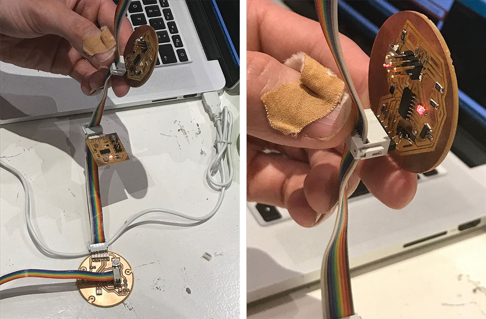
For the group assignment we used boards from the past were still working and have a FTDI connection. To keep things simple we settled on using serial communication to get the boards talking to each other. All boards are connected through a ribbon cable in a lineair fashion. Through this cable all boards are powered and do their communication using TX and RX. The first board is called a bridge, the others in line are all nodes. The bridge sends out a message over the TX to all nodes, all nodes are listening on RX. In our case the bridge is sending out a message, a node number. The nodes are initially only listening on the RX and are programmed to respond to a certain message, their node number. Once their node number is send they will run their program. It is also possible to describe what the nodes should do when their number is not being called.
Joey and Rutger programmed the bridge, I programmed the first node and Micky the second.
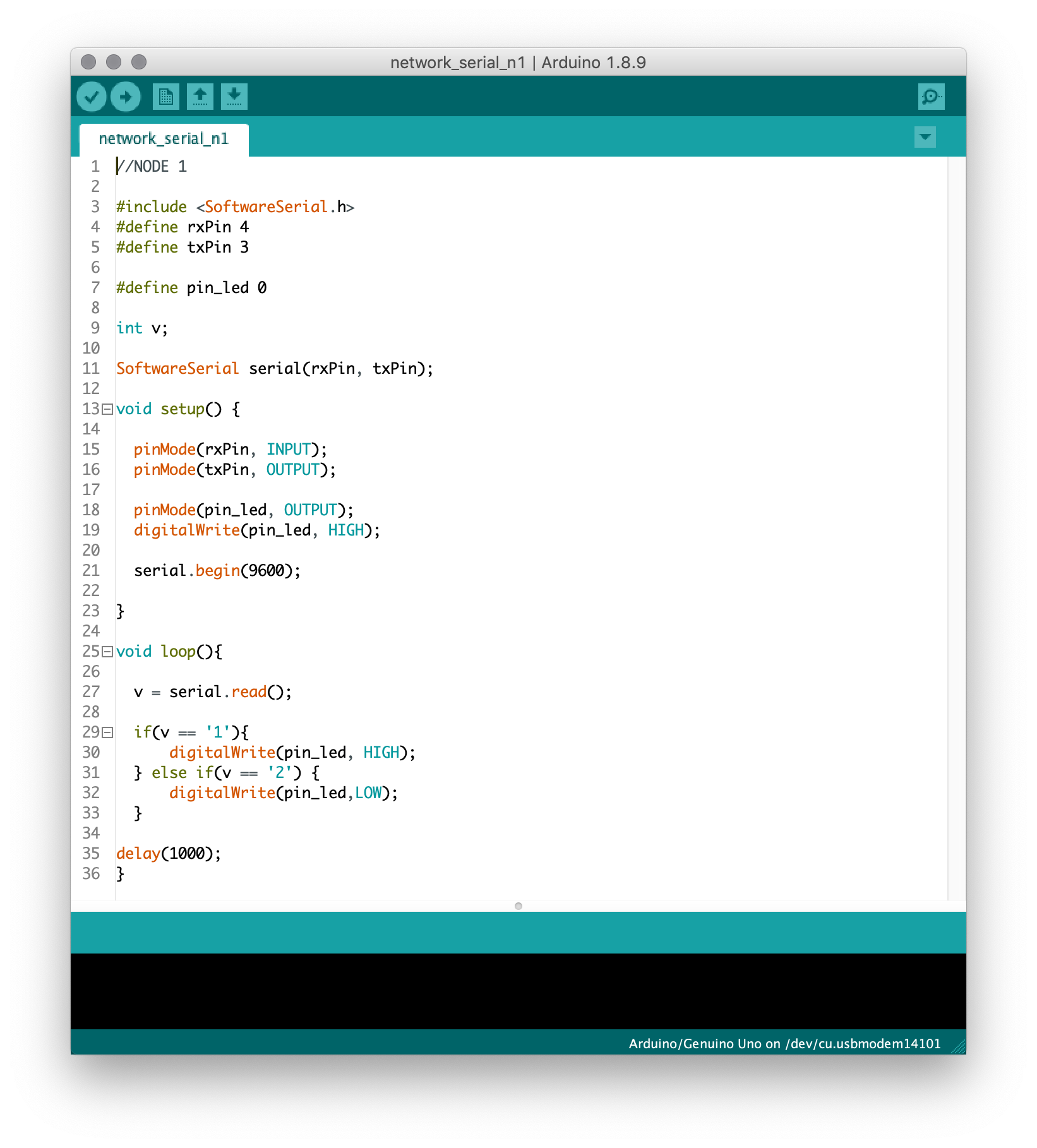
Here is my script:
Indiviual assignment
So jumping in time it's now weeks later. For my final project I want to incorporate a OLED screen. These screens come with different pin outs and the one we had in the lab has I2C pins (VCC GND SDA SCL). I2C is slightly more complex to use than serial communication but comes with some advantages. First one is, it needs less wire and another big advantage is that I2C ensures that data sent is received by the slave. The first board in line is called a master and all the other boards are called slaves. The slaves ar all given an adress, in case of my OLED screen this is already done. If you use your own board you have to specify this yourself. All adresses need to be unique and need a specific length, they look like this: 0X3C.
Board design
The board I designed for my final project is based on a Satsha kit. Since it hosts many more things I will only describe the OLED connection. You can find more on the project page about this board.
The OLED screen is pretty straightforward since it used I2C for communication. It needs VCC, GND, SCL and SDA for it's communication to the board. SCL and SDA can only be connected to pin 28 and 27 on the ATMEGA. Since the connection is pretty short no additinal resistors are needed. Keep in mind the courtyard space that the OLED will need. I didn't do this good enough in my design therefore it was a bit akwardly positioned.
Programming
Since I want to connect a excisting device to my network I have to figure out what the adress is of my device. Normally you can find this in de datasheet. Since I wasn't able to find it I used a I2C scanner that I found on Arduino.cc.
Just upload the sketch to your board and connect the device (slave). In the monitor you can see a live update on what devices are found. Mine is called OX3C.

To programm the OLED I used a specific library from Adafruit. Once I knew the adress of the OLED I added it in this line:
display.begin(SSD1306_SWITCHCAPVCC, 0x3C); Using this special site I converted a image to a Arduino IDE bitmap. The size of my OLED is 128 x 64 px. For code output format select Arduino code. When your finished click "generate code". Now copy paste the code into the Arduino IDE. There is a really good explanation on how to do this here.
/*
  OLED bitmap test

  This example shows how to display a logo on a 128x64 px i2c oled display.

  A .png with the correct size can be converted via this site into an arduino code.

  http://javl.github.io/image2cpp/

  Sources:
  https://lastminuteengineers.com/oled-display-arduino-tutorial/

  by Anne Vlaanderen 2019
*/


#include <SPI.h>
#include <Wire.h>
#include <Adafruit_GFX.h>
#include <Adafruit_SSD1306.h>

Adafruit_SSD1306 display(-1);

// Bitmap of IntroPensieve Image
const unsigned char IntroPensieve [] PROGMEM = {
  0x00, 0x00, 0x00, 0x00, 0x00, 0x00, 0x00, 0x00, 0x00, 0x00, 0x00, 0x00, 0x00, 0x00, 0x00, 0x00,
  0x00, 0x00, 0x00, 0x00, 0x00, 0x00, 0x00, 0x00, 0x00, 0x00, 0x00, 0x00, 0x00, 0x00, 0x00, 0x00,
  0x00, 0x00, 0x00, 0x00, 0x00, 0x00, 0x00, 0x00, 0x00, 0x00, 0x00, 0x00, 0x00, 0x00, 0x00, 0x00,
  0x00, 0x00, 0x00, 0x00, 0x00, 0x00, 0x00, 0x00, 0x00, 0x00, 0x00, 0x00, 0x00, 0x00, 0x00, 0x00,
  0x00, 0x00, 0x00, 0x00, 0x00, 0x00, 0x00, 0x00, 0x00, 0x00, 0x00, 0x00, 0x00, 0x00, 0x00, 0x00,
  0x00, 0x00, 0x00, 0x00, 0x00, 0x00, 0x00, 0x00, 0x00, 0x00, 0x00, 0x00, 0x00, 0x00, 0x00, 0x00,
  0x00, 0x00, 0x00, 0x00, 0x00, 0x00, 0x00, 0x00, 0x00, 0x00, 0x00, 0x00, 0x00, 0x00, 0x00, 0x00,
  0x00, 0x00, 0x00, 0x00, 0x00, 0x00, 0x00, 0x00, 0x00, 0x00, 0x00, 0x00, 0x00, 0x00, 0x00, 0x00,
  0x00, 0x00, 0x00, 0x00, 0x00, 0x00, 0x00, 0x00, 0x00, 0x00, 0x00, 0x00, 0x00, 0x00, 0x00, 0x00,
  0x00, 0x00, 0x00, 0x00, 0x20, 0x00, 0x00, 0x00, 0x00, 0x00, 0x00, 0x00, 0x00, 0x00, 0x00, 0x00,
  0x02, 0x00, 0x00, 0x00, 0x00, 0x00, 0x00, 0x00, 0x00, 0x00, 0x00, 0x00, 0x00, 0x00, 0x00, 0x00,
  0x00, 0x00, 0x00, 0x00, 0x40, 0x00, 0x00, 0x00, 0x00, 0x00, 0x00, 0x00, 0x00, 0x00, 0x00, 0x00,
  0x01, 0x00, 0x00, 0x00, 0x00, 0x00, 0x00, 0x00, 0x00, 0x00, 0x00, 0x00, 0x00, 0x00, 0x00, 0x00,
  0x00, 0x00, 0x00, 0x00, 0x80, 0x00, 0x00, 0x00, 0x00, 0x00, 0x00, 0x00, 0x00, 0x00, 0x00, 0x00,
  0x00, 0x00, 0x00, 0x00, 0x00, 0x00, 0x00, 0x00, 0x00, 0x00, 0x00, 0x00, 0x00, 0x00, 0x00, 0x00,
  0x00, 0x00, 0x00, 0x00, 0x00, 0x00, 0x00, 0x00, 0x00, 0x00, 0x00, 0x00, 0x00, 0x00, 0x00, 0x00,
  0x00, 0x00, 0x00, 0x00, 0x00, 0x00, 0x00, 0x00, 0x00, 0x00, 0x00, 0x00, 0x00, 0x00, 0x00, 0x00,
  0x00, 0x00, 0x00, 0x00, 0x00, 0x00, 0x00, 0x00, 0x00, 0x00, 0x00, 0x00, 0x00, 0x00, 0x00, 0x00,
  0x00, 0x00, 0x00, 0x01, 0x00, 0x00, 0x00, 0x00, 0x00, 0x00, 0x00, 0x00, 0x00, 0x00, 0x00, 0x00,
  0x00, 0x34, 0x00, 0x26, 0x00, 0x00, 0x00, 0x00, 0x00, 0x00, 0x00, 0x00, 0x00, 0x00, 0x00, 0x00,
  0x00, 0x0a, 0x40, 0x68, 0x00, 0x00, 0x00, 0x00, 0x00, 0x00, 0x00, 0x00, 0x00, 0x00, 0x00, 0x00,
  0x00, 0x0f, 0xa2, 0xf8, 0x00, 0x00, 0x00, 0x00, 0x00, 0x00, 0x00, 0x00, 0x00, 0x00, 0x00, 0x00,
  0x00, 0x03, 0xe3, 0xc0, 0x00, 0x00, 0x00, 0x00, 0x00, 0x00, 0x00, 0x00, 0x00, 0x00, 0x00, 0x00,
  0x00, 0x00, 0x22, 0x00, 0x00, 0x00, 0x00, 0x00, 0x00, 0x00, 0x00, 0x00, 0x00, 0x00, 0x00, 0x00,
  0x00, 0x01, 0xa4, 0x80, 0x01, 0xff, 0x00, 0x00, 0x00, 0x00, 0x03, 0x00, 0x00, 0x00, 0x00, 0x00,
  0x00, 0x01, 0xff, 0x80, 0x01, 0xff, 0x80, 0x00, 0x00, 0x00, 0x03, 0x00, 0x00, 0x00, 0x00, 0x00,
  0x00, 0x00, 0xff, 0x80, 0x01, 0x81, 0xc0, 0x00, 0x00, 0x00, 0x00, 0x00, 0x00, 0x00, 0x00, 0x00,
  0x00, 0x00, 0x3c, 0x00, 0x01, 0x80, 0xc0, 0x00, 0x00, 0x00, 0x00, 0x00, 0x00, 0x00, 0x00, 0x00,
  0x00, 0x00, 0x3c, 0x00, 0x01, 0x80, 0xc1, 0xe0, 0xde, 0x07, 0xc3, 0x07, 0x86, 0x04, 0x1e, 0x00,
  0x00, 0x00, 0x1c, 0x00, 0x01, 0x80, 0xc7, 0xf8, 0xff, 0x0f, 0xe3, 0x1f, 0xe6, 0x0c, 0x7f, 0x80,
  0x00, 0x00, 0x1e, 0x00, 0x01, 0x81, 0xce, 0x18, 0xe3, 0x98, 0x33, 0x38, 0x62, 0x0c, 0xe1, 0x80,
  0x00, 0x00, 0x3e, 0x00, 0x01, 0xff, 0x8c, 0x0c, 0xc1, 0x98, 0x03, 0x30, 0x33, 0x08, 0xc0, 0xc0,
  0x00, 0x00, 0xfe, 0x00, 0x01, 0xff, 0x0f, 0xfc, 0xc1, 0x8e, 0x03, 0x3f, 0xf3, 0x18, 0xff, 0xc0,
  0x00, 0x00, 0xfe, 0x00, 0x01, 0x80, 0x0f, 0xfc, 0xc1, 0x87, 0xe3, 0x3f, 0xf1, 0x10, 0xff, 0xc0,
  0x00, 0x00, 0xfe, 0x00, 0x01, 0x80, 0x0c, 0x00, 0xc1, 0x80, 0x73, 0x30, 0x01, 0xb0, 0xc0, 0x00,
  0x00, 0x01, 0xff, 0x00, 0x01, 0x80, 0x0c, 0x18, 0xc1, 0x98, 0x33, 0x30, 0x60, 0xb0, 0xc1, 0x80,
  0x00, 0x01, 0xff, 0x00, 0x01, 0x80, 0x0e, 0x18, 0xc1, 0x98, 0x73, 0x38, 0x60, 0xe0, 0xe1, 0x80,
  0x00, 0x01, 0xff, 0x00, 0x01, 0x80, 0x07, 0xf0, 0xc1, 0x8f, 0xe3, 0x1f, 0xc0, 0xe0, 0x7f, 0x00,
  0x00, 0x01, 0xff, 0x00, 0x01, 0x80, 0x01, 0xe0, 0xc1, 0x87, 0xc3, 0x07, 0x80, 0x40, 0x1e, 0x00,
  0x00, 0x01, 0xff, 0x00, 0x00, 0x00, 0x00, 0x00, 0x00, 0x00, 0x00, 0x00, 0x00, 0x00, 0x00, 0x00,
  0x00, 0x00, 0xff, 0x00, 0x00, 0x00, 0x00, 0x00, 0x00, 0x00, 0x00, 0x00, 0x00, 0x00, 0x00, 0x00,
  0x00, 0x00, 0xff, 0x00, 0x00, 0x00, 0x00, 0x00, 0x00, 0x00, 0x00, 0x00, 0x00, 0x00, 0x00, 0x00,
  0x00, 0x00, 0xff, 0x00, 0x00, 0x00, 0x00, 0x00, 0x00, 0x00, 0x00, 0x00, 0x00, 0x00, 0x00, 0x00,
  0x00, 0x00, 0xfe, 0x00, 0x00, 0x00, 0x00, 0x00, 0x00, 0x00, 0x00, 0x00, 0x00, 0x00, 0x00, 0x00,
  0x00, 0x00, 0x7e, 0x00, 0x00, 0x00, 0x00, 0x00, 0x00, 0x00, 0x00, 0x00, 0x00, 0x00, 0x00, 0x00,
  0x00, 0x00, 0x7e, 0x00, 0x00, 0x00, 0x00, 0x00, 0x00, 0x00, 0x00, 0x00, 0x00, 0x00, 0x00, 0x00,
  0x00, 0x00, 0x7e, 0x00, 0x00, 0x00, 0x00, 0x00, 0x00, 0x00, 0x00, 0x00, 0x00, 0x00, 0x00, 0x00,
  0x00, 0x00, 0x7c, 0x00, 0x00, 0x00, 0x00, 0x00, 0x00, 0x00, 0x00, 0x00, 0x00, 0x00, 0x00, 0x00,
  0x00, 0x00, 0x5c, 0x00, 0x02, 0x00, 0x08, 0x00, 0x00, 0x11, 0x40, 0x00, 0x02, 0x00, 0x00, 0x00,
  0x00, 0x00, 0x5c, 0x00, 0x02, 0x00, 0x0c, 0x00, 0x00, 0x11, 0x40, 0x00, 0x02, 0x00, 0x00, 0x00,
  0x00, 0x00, 0x5c, 0x00, 0x03, 0xd2, 0x14, 0xf7, 0x9c, 0x11, 0x4e, 0x73, 0xde, 0x73, 0x73, 0xc0,
  0x00, 0x00, 0x5c, 0x00, 0x02, 0x52, 0x16, 0xd6, 0x52, 0x0a, 0x52, 0x4a, 0x52, 0x9a, 0x4a, 0x40,
  0x00, 0x00, 0x7c, 0x00, 0x02, 0x54, 0x3e, 0x96, 0x5e, 0x0a, 0x4e, 0x7a, 0x52, 0xfa, 0x7a, 0x40,
  0x00, 0x00, 0x7c, 0x00, 0x02, 0x4c, 0x22, 0x96, 0x52, 0x0e, 0x5e, 0xfa, 0x52, 0x92, 0x4a, 0x40,
  0x00, 0x00, 0x1c, 0x00, 0x03, 0x8c, 0x21, 0x96, 0x5c, 0x04, 0x5f, 0x7a, 0x5e, 0x72, 0x72, 0x40,
  0x00, 0x00, 0x10, 0x00, 0x00, 0x08, 0x00, 0x00, 0x00, 0x00, 0x00, 0x00, 0x00, 0x00, 0x00, 0x00,
  0x00, 0x00, 0x00, 0x00, 0x00, 0x18, 0x00, 0x00, 0x00, 0x00, 0x00, 0x00, 0x00, 0x00, 0x00, 0x00,
  0x00, 0x00, 0x00, 0x00, 0x00, 0x00, 0x00, 0x00, 0x00, 0x00, 0x00, 0x00, 0x00, 0x00, 0x00, 0x00,
  0x00, 0x00, 0x00, 0x00, 0x00, 0x00, 0x00, 0x00, 0x00, 0x00, 0x00, 0x00, 0x00, 0x00, 0x00, 0x00,
  0x00, 0x00, 0x00, 0x00, 0x00, 0x00, 0x00, 0x00, 0x00, 0x00, 0x00, 0x00, 0x00, 0x00, 0x00, 0x00,
  0x00, 0x00, 0x00, 0x00, 0x00, 0x00, 0x00, 0x00, 0x00, 0x00, 0x00, 0x00, 0x00, 0x00, 0x00, 0x00,
  0x00, 0x00, 0x00, 0x00, 0x00, 0x00, 0x00, 0x00, 0x00, 0x00, 0x00, 0x00, 0x00, 0x00, 0x00, 0x00,
  0x00, 0x00, 0x00, 0x00, 0x00, 0x00, 0x00, 0x00, 0x00, 0x00, 0x00, 0x00, 0x00, 0x00, 0x00, 0x00,
  0x00, 0x00, 0x00, 0x00, 0x00, 0x00, 0x00, 0x00, 0x00, 0x00, 0x00, 0x00, 0x00, 0x00, 0x00, 0x00
};
void setup()
{
  // initialize with the I2C address 0x3C
  display.begin(SSD1306_SWITCHCAPVCC, 0x3C);

  // Clear the display.
  display.clearDisplay();

  // Display bitmap
  display.drawBitmap(0, 0,  IntroPensieve, 128, 64, WHITE);
  display.display();

}

void loop() {}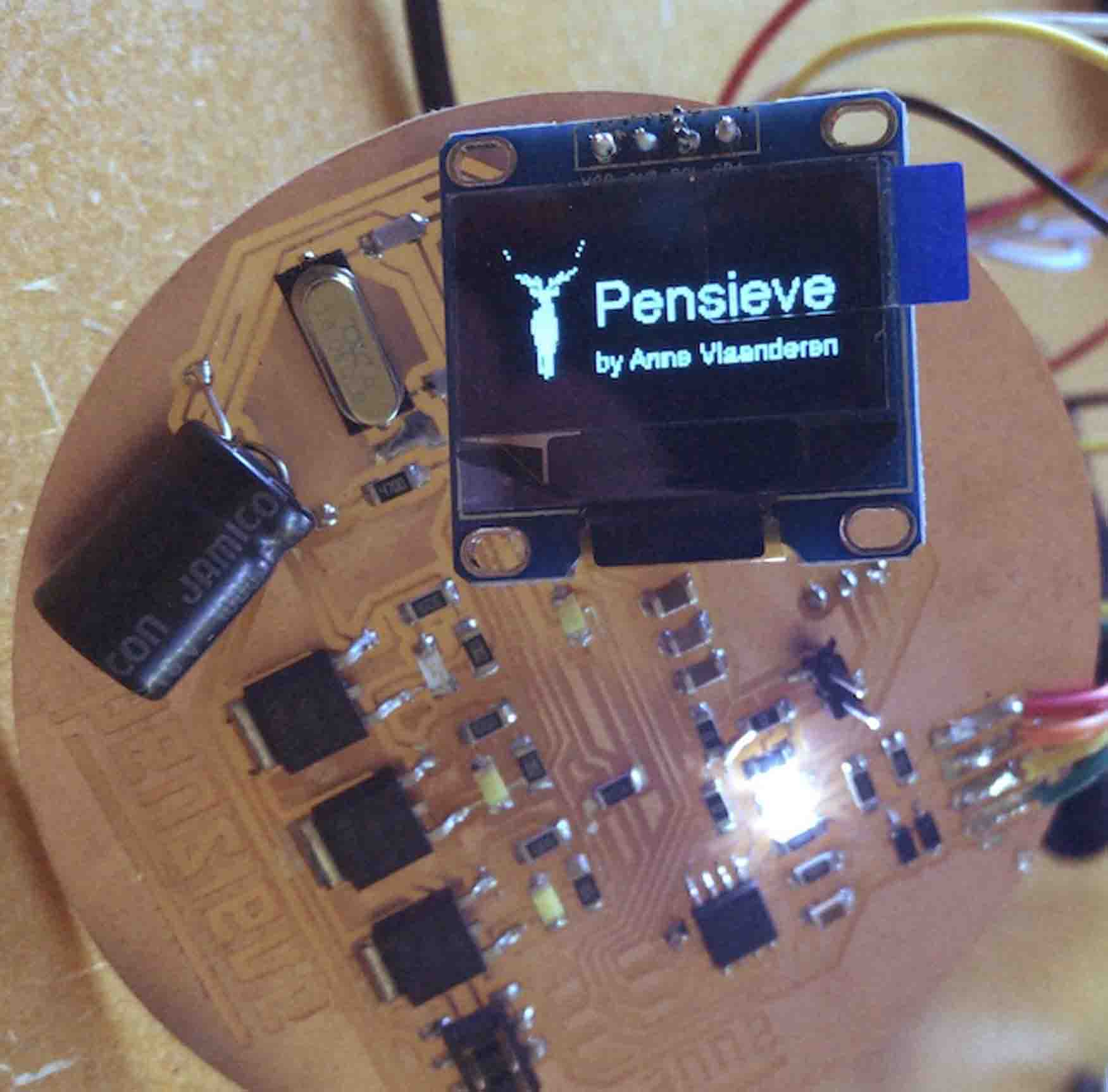
I2C LED blinks
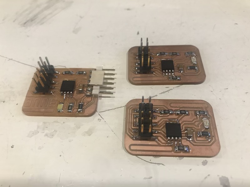
I made 3 different boards to test out I2C communication. All boards have a ATTINY85 chip and have LED's. The master has a white LED and the slaves have blue LEDS. Since it's all pretty new to me I decided to make it really basic.
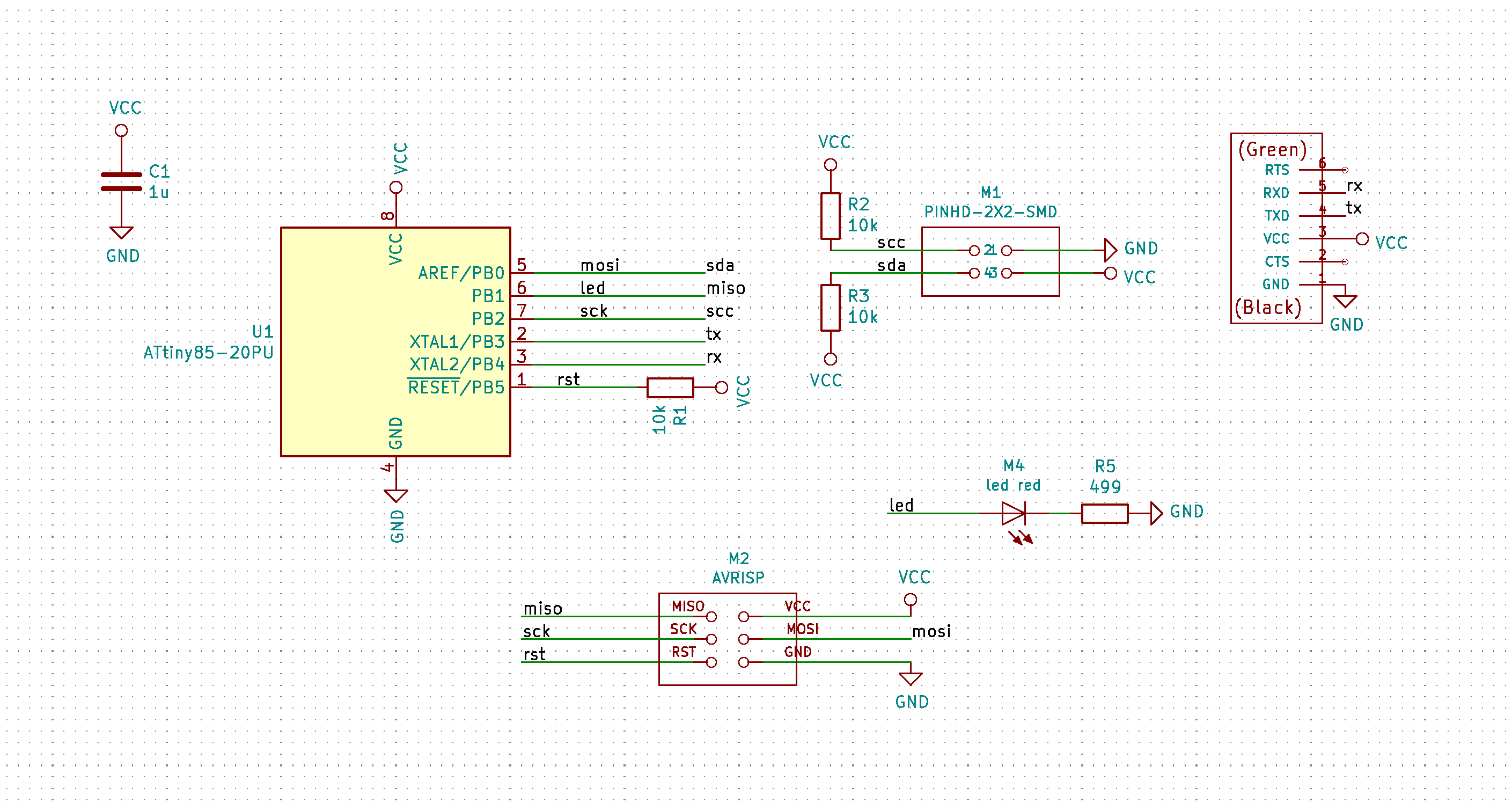
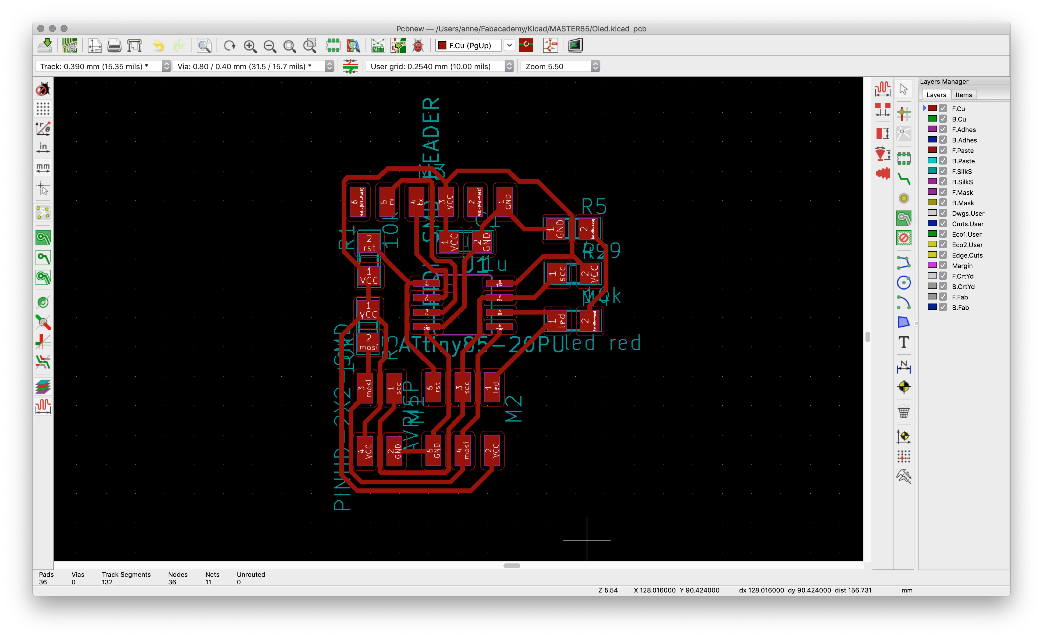
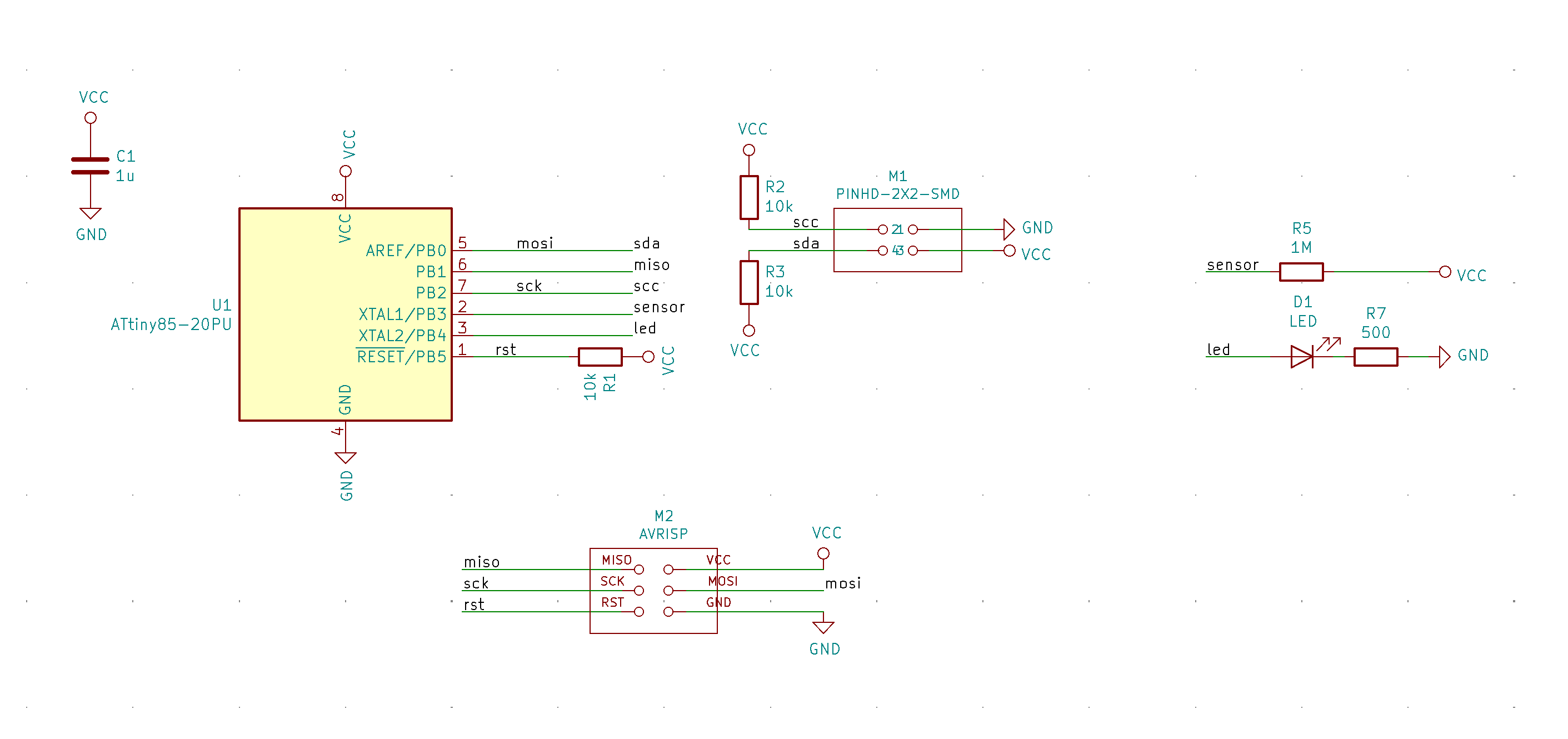
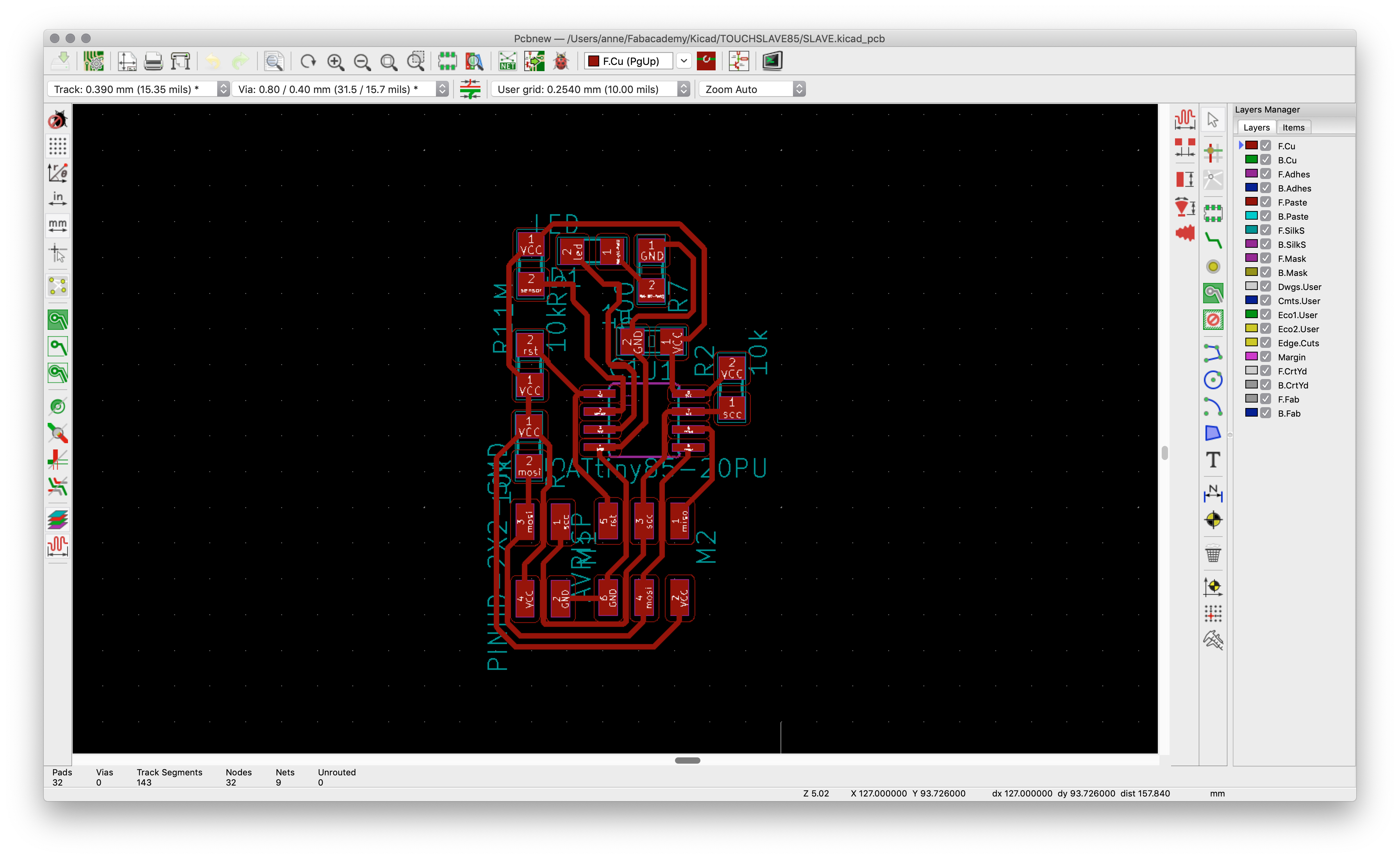
All boards have a ISP header (6 pins) and a I2C header (4 pins), the master also has a FTDI connection for debugging. The boards are connected through a ribbon cable with 4 wires and connectors (VCC GND SDA SCL). Through powering the master all boards receive power.
PCB design master
PCB design slave
After designing the boards in Kicad I milled them on the modela. I soldered them all in one go and put on their bootloaders. On the back of each board I wrote some simple things to keep track of them. Like on what pin the LED was connected, their addresses and for the master where the ground of the FTDI connection was.
The master has no address.
Slave one is 0x01
Slave two is 0x02
The library I used to do this is TinyWireM and TinyWireS. These are specifically for the ATTINY chips.
Programming
I started by programming the Master - the masters job is to start talking to one of the slaves and than send them a message. It starts by calling an adress and than sending a number. The slave in it's turn responds depending on the number it receives. In my case, if the slave is called and number 1 is send the led will blink for a second and switch of again. Than the master goes to the next adress and does the same thing all over again. The result, two LEDS that blink, one after the other. To make the masters communication visible it also blinks for each message that it sends.
/*Master code for ATTINY master by Anne Vlaanderen*/
#include <TinyWireM.h>
#define led1 0x01 // led 1
#define led2 0x02 // led 2


int LED = 1;
int WAIT = 1000;

void setup() {
pinMode(LED, OUTPUT);
TinyWireM.begin();
}
void loop() {

// led 1
TinyWireM.beginTransmission(led1);
TinyWireM.send(1);
TinyWireM.endTransmission();
TinyWireM.requestFrom(led1,1); // Request 1 byte from slave
analogWrite(LED,20);
delay(WAIT);

TinyWireM.beginTransmission(led1);
TinyWireM.send(0);
TinyWireM.endTransmission();
analogWrite(LED,LOW);
delay(WAIT);


// led 2
TinyWireM.beginTransmission(led2);
TinyWireM.send(1);
TinyWireM.endTransmission();
analogWrite(LED,20);
delay(WAIT);
TinyWireM.beginTransmission(led2);
TinyWireM.send(0);
TinyWireM.endTransmission();
analogWrite(LED,LOW);
delay(WAIT);

}
Here you can see the code I wrote for the slave. When the boards receive power they blink rapidly 3 times. This tells me the LEDS are working and the boards are connected properly. In the loop there is an if /else if statement that checks the message and either swithes the LED on or off. Don't forget to change the adress for each slave!!
/*Slave code for ATTINY Slave by Anne Vlaanderen*/
#include <TinyWireS.h>

#define output (8)
#define I2C_SLAVE_ADDR 0x01

volatile byte msg = 0;

void setup() {
  TinyWireS.begin(I2C_SLAVE_ADDR);
  pinMode(output, OUTPUT);

  for (int i = 0; i <= 2; i++) {
  digitalWrite(output,HIGH);
  delay(300);
  digitalWrite(output,LOW);
  delay(300);
  }
}


void loop() {

if (TinyWireS.available()){
  msg = TinyWireS.receive();
  }

if (msg == 1) {
    digitalWrite(output, HIGH);
    delay(1000);
     msg = 0;
     }
else if (msg == 0) {
    digitalWrite(output, LOW);
    }

delay(1000);
}
What I did wrong & improvements
- The OLED screen has 4 male pins out of the box. I didn't have any female headers that I could use to mount it directly on the board. Also the courtyard space was a bit tight. Headers double stacked, can't fit and also the screen was larger that expected. So better headers and lay out should solve this.
- While writing the code I had some issues where the image didn't display. This was because I was loading the bitmap below the setup, it needs to be above. If it's not in the memory it cannot be called yet.
- On the site that generates the bitmap I had some issues with the interface - the interaction is sometimes a bit buggy so pay close attention when uploading and refresh every now and then.
Files
Sketch for displaying Bitmap in OLED
Design files + Kicad master i2c board
Design files + Kicad slave i2c board
Design files + Kicad Pensieve board