Output devices
This week my goal was to finalise week 11 (output devides) and combine it with week 12. Last week I made a GSR (Galvanic Skin Response sensor) and this week I wanted to add an output to this, a aroma vapor and a screen to read data. Last but not least I wanted to give the Satsha kit another try since I didn't succeed last time.
Input devices
Hardware
USB drive
Modela MDX20
Soldering iron - Weller WS 81 (SMD tip)
Powerbench
Artisjet UV printer
Software
FabModules
KiCad
Tools
1/32 inch milling bit
1/64 inch milling bit
Scraper
Materials
FR-1 PCB blanks (1.8 mm thickness)
Double sided tape (good quality)
Rubbing alcohol
Resources
Satshakit
Group assignment
For the group assignment we measured the power consumptiom of a device. The best way we did this was by using a external power supply. There are several options in the lab but the one we used was one made by our instructor. It consists of a power supply with a regulator hooked and display up to it.
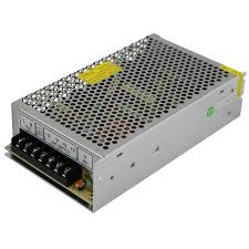
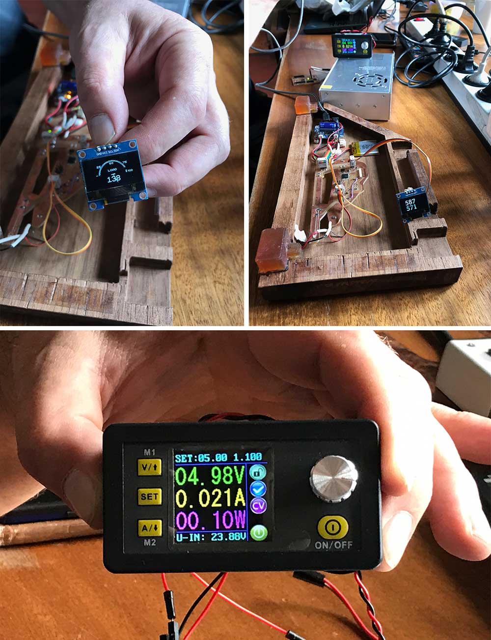
We set the settings too output voltage (5V) and current (1A). The display shows the powerconsumption in both current as watt
On the display you can now see the change in the voltage and amperage. By connecting your board to the device you can read how much of the supplied power is used. In this case: with a 4.98 voltage a current of 0.021 A (21 milliamps) is being used - this is a 0.1 watts device.
Satshakit
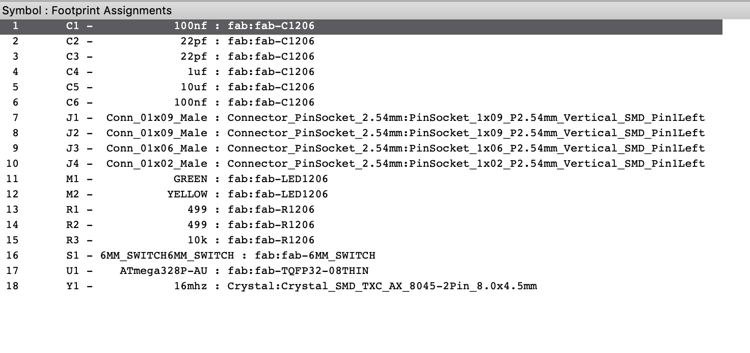
Last week I really wanted to make the Satsha kit. I had one evening to redesign the board and make it ready for milling. Since I was designing from home I couldn't find all parts and was struggeling with finding the correct footprints. Since I wasn't in the lab I gave up after a while. This week I was more prepared - I made a list of all the parts, photograped them at the lab and wrote down all their details.
The part storage in our lab consists of cabinets with small drawers, each drawer has a label with the part name on the outside and inside the drawer you find the parts and the original label from Digikey or Farnell.
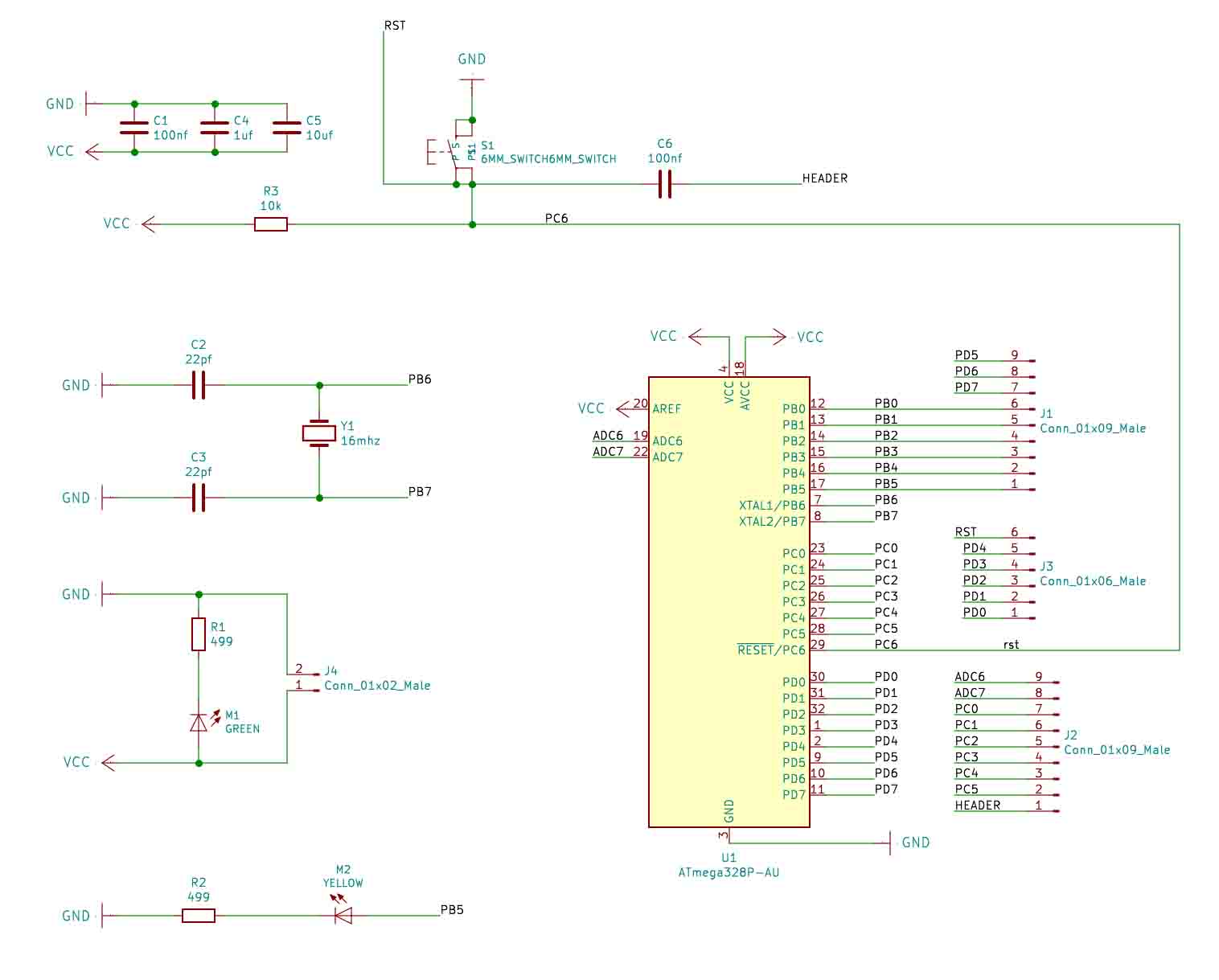
I downloaded the Eagle files from Satshakit Github and imported it into Kicad. This is what I did last week and it kind of works but not really wel since all footprints and names are slightly different. I tried to fix this and saved it as a Kicad file. Since it's an imported file it will keep a Eagle extension. Instead of doing some research to figure out if this can be fixed I decided to redraw the board since it wasn't to much of an effort. Also I compared the board to the one my instructor Henkie made last year and I noticed the pin through hole components. I replaced them all with their surface mount alternatives that were available our lab. I exported the final design as a SVG and imported it into Photoshop. In Photoshop I drew an outline and prepared a design for the UV-printing.
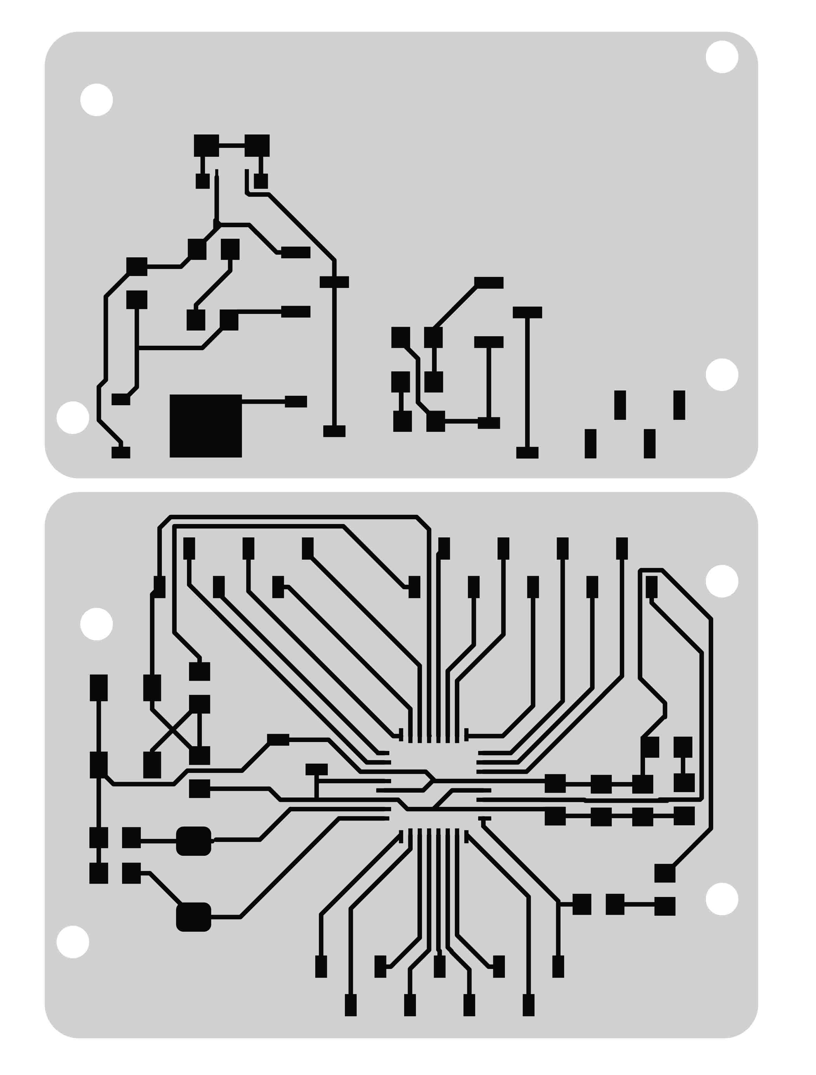
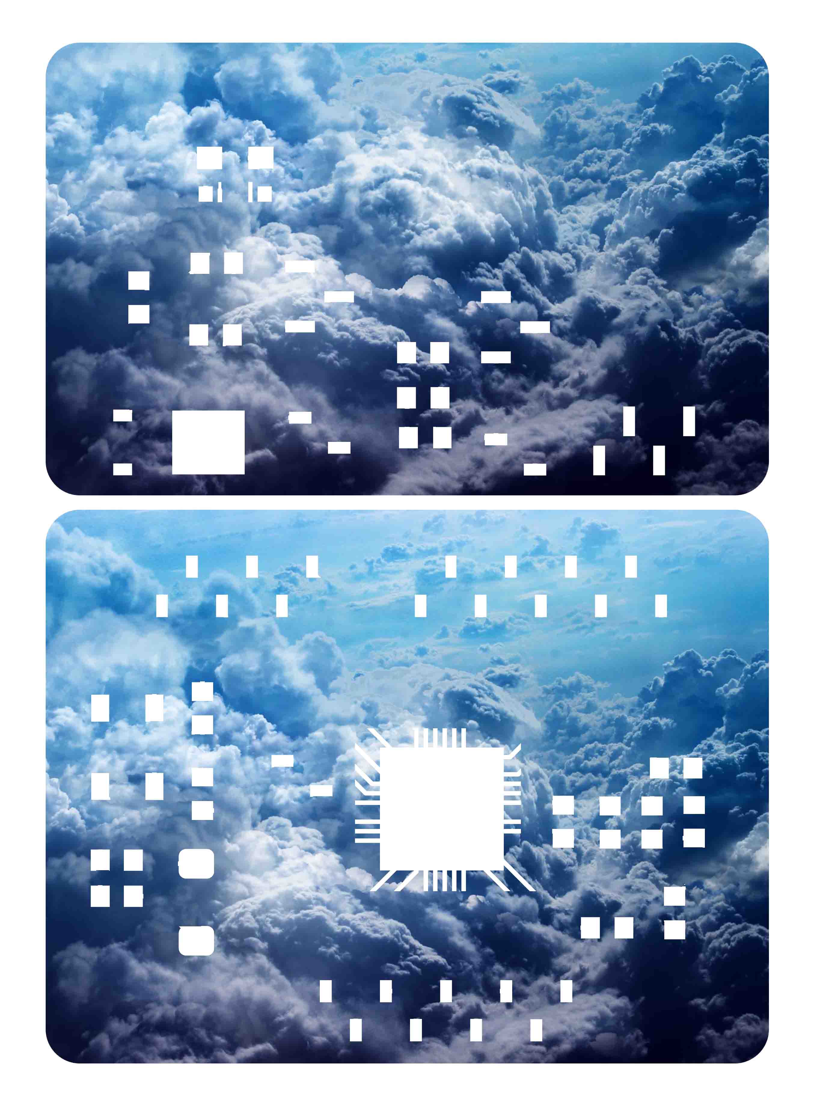
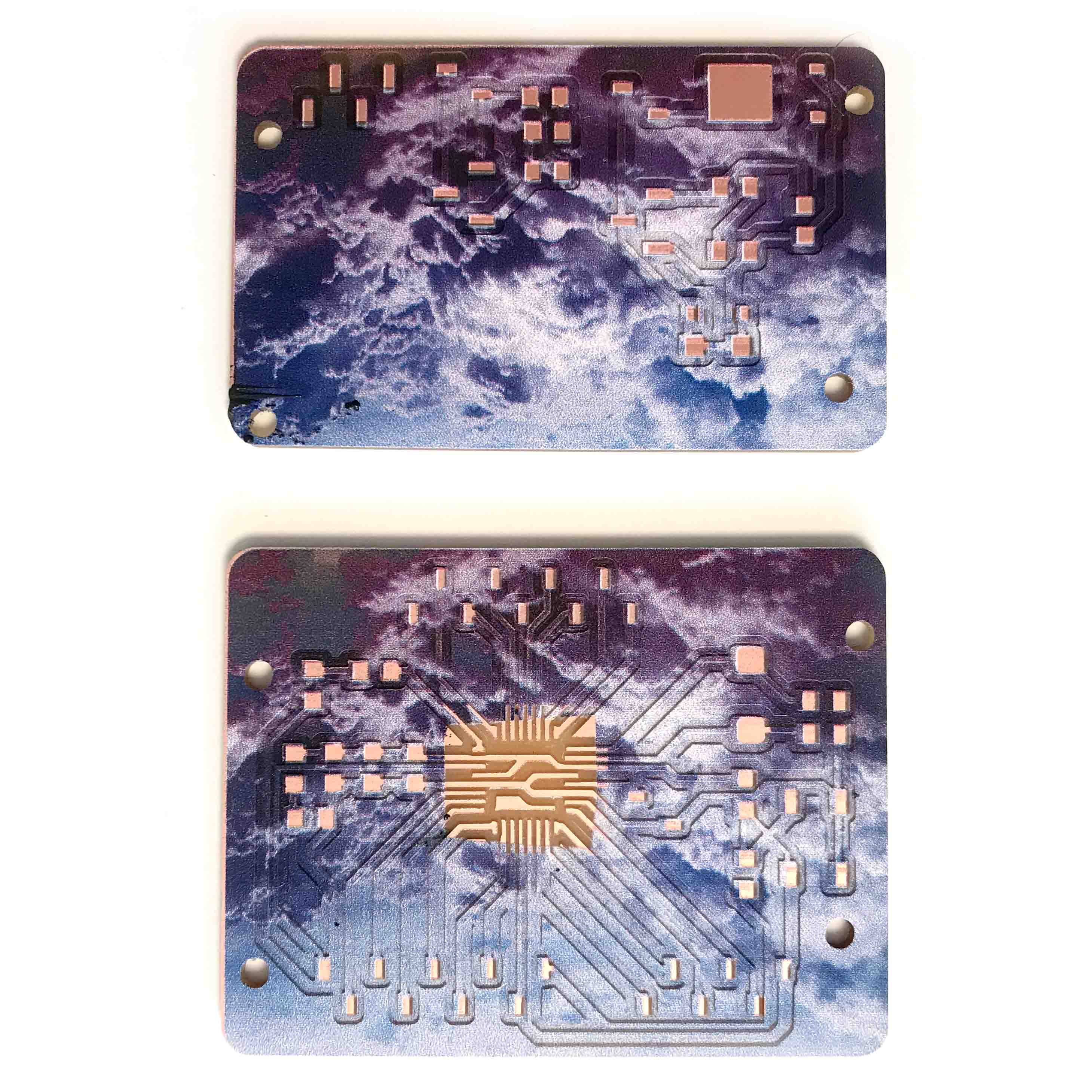
The milling bits available are a bit brittle this limits us to a 1 mm/s milling speed. Just the Satshakit board takes about 2 hrs to mill. The first time in my milling bit broke halfway through the process. I zeroed it in one of the corners so the cuts were a bit deeper in some parts, this caused a little bit extra stress on the bit and this is likely the cause of the milling bit breaking.
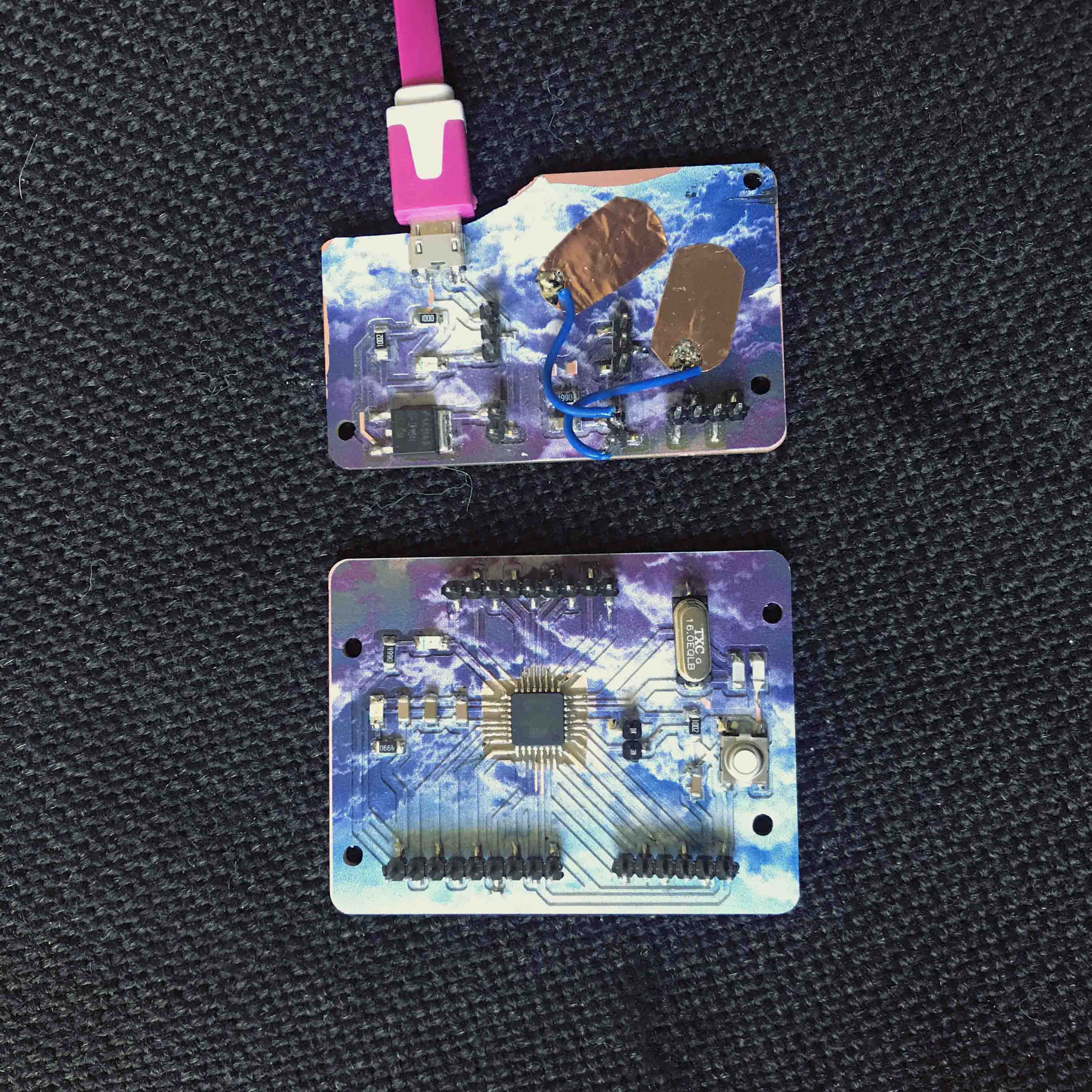
This was a bit unfortanate that I had to start over since I hadn't booked enough time. Fortunatly a spot became available so a bit later I was able to remill the board. The second time went completely fine. I printed my design on top and soldered all compnents.
Output board
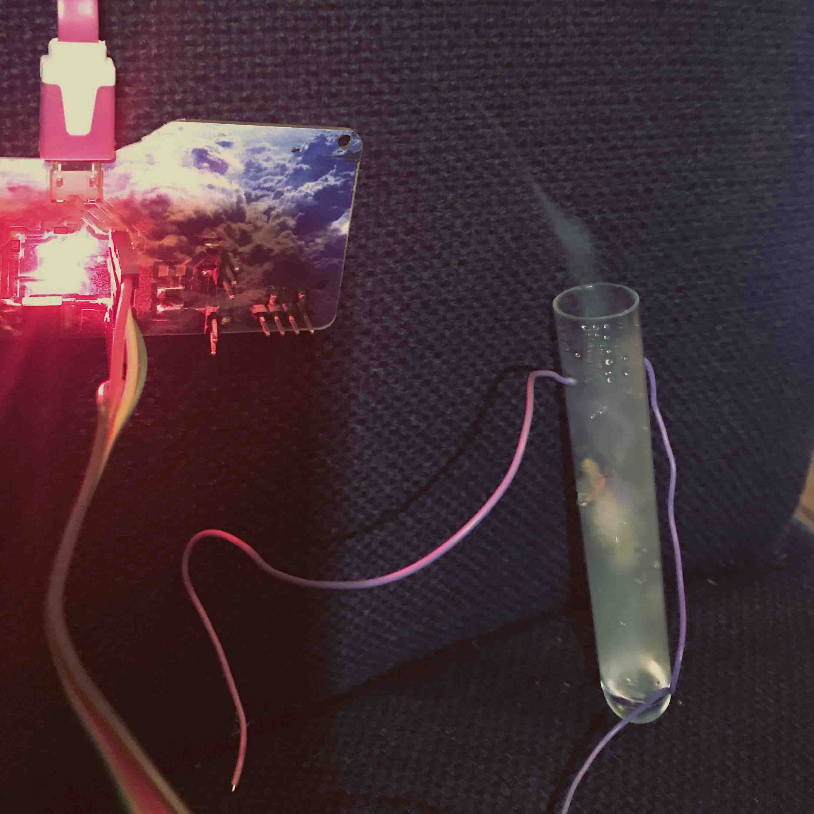
For the second part of the design I made a seperate board combining the input and output week. For the this week I added a OLED screen and a aroma vapor. The aroma vapor consists of a hot wire and a cotton ball soaked in glycerine and essential oil (5:1 based on volume). The hot wire is wrapped around the cotton and soldered to two wires. When the hot wire heats up there is a bit of soothing smoke.
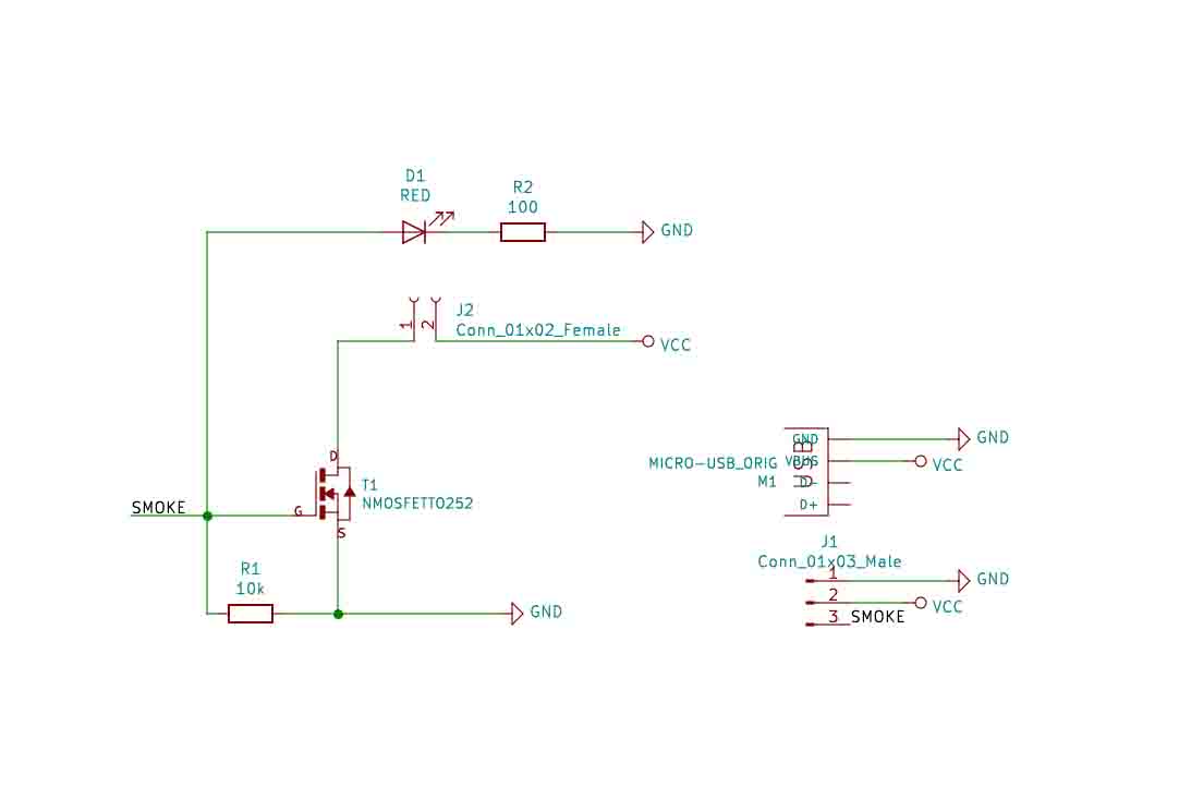
For this experiment I cut off a piece of hot wire with a resistance of roughly 5 ohms (when wrapped) and is connected at the female headers. The data pins on the microcontroller (Atmega) can only supply 200mA, this is does not create enough heat to create smoke. To get more current on the hotwire a different power supply (5V) is needed. I used a usb charger from an old phone (5V/2A) and connected it to the micro usb port. The hotwire is controlled with a mosfet (N). The mosfet works like a button that get's pressed with a digital signal. The 'button' is open or closed and creates a open or closed cirquit for the hotwire.
The test code I used is a modified blink sketch from the Arduino examples. It switches the smoke on for six seconds and off for 15 seconds. Also the LED on the board goes on or off when the smoke does. This is a nice feature to add for troubleshooting since it tells you clearly the state of the smoke without having to hook it up.
Connecting everything
Start by unplugging everything from the computer. To connect the output board to the Satshakit the 3 header pins can be used. Connect 3 female jumpers, one for VCC, one for ground and the last one for data (A5 on Satshakit). Check the schematic to ensure you are connecting the correct ones. Connect a power adapter (5V - 2A) with micro usb cable to the output board. This will power both the Satshakit and the outputboard.
 // the setup function runs once when you press reset or power the board
void setup() {
  // initialize digital pin A5 as an output.
  pinMode(A5, OUTPUT);
}

// the loop function runs over and over again forever
void loop() {
  digitalWrite(A5, HIGH);   // turn the LED on (HIGH is the voltage level)
  delay(6000);                       // wait for a second
  digitalWrite(A5, LOW);    // turn the LED off by making the voltage LOW
  delay(15000);                       // wait for a second
}
Lastly to read out all data and states of my sensor and actuator I added a OLED screen. It only has 4 connection pins, 2 for power and 2 for data. I followed this tutorial from Instructables to test it out. Once I uploaded the sketch it didn't work, I forgot to change the adress of the screen in the code and the two data wires were in the wrong positions. The Instructable page implies a additional power supply is needed, this is not true for a OLED screen of this size (or smaller).
arduino code for OLED
Extra
At home I have a Modela that I would like to use during the Fabacademy. Unfortantly I had issues connecting to it. In the past I used a PC with the native software but since I work on mac now I wanted to move to mods.
From Gitlab mods I followed the instructions. Unfortunatly this was not working for me inmediatly. Since I have the best instructor in the world I was able to get it to work. There were a few things that I either missed or were not documentented.
- Install serial port.
sudo npm install serialport - Install ws.
sudo npm install ws - Properly install the Keyspan adapter (also use a USB2 hub for newer macs) -> Instructions
- Find the correct port name, connect the devic and go to the dev folder in the terminal, list all items and look for your device.
For me it's:
tty.USA19H1412P1.1
To start mods all I have to do is:
MBP:~/Fabmodules/mods/js$ node serialserver.js ::ffff:127.0.0.1 1234Files
PCB traces output week - new - fixed crystal and more margin for button
PCB projectfolder Kicad
PCB traces output week
PCB design outputweek