INPUT DEVICES | WEEK 10
A0 Link to group assignment.
You can see the group assignment hereI chose this Output device because I though that It would be easy, a way to finish the assignment quick, before start with the one that i'm really interested in: the accelerometer but, well, the problems started just with this one.
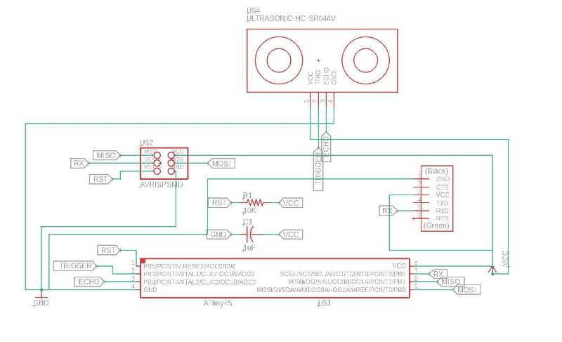
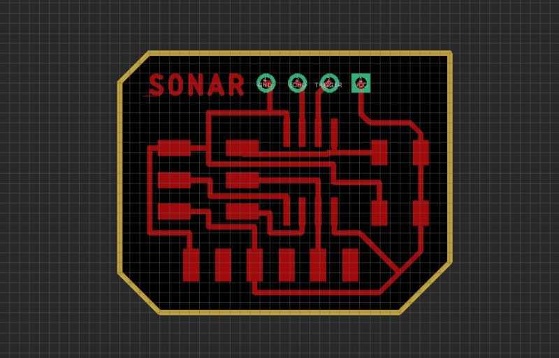
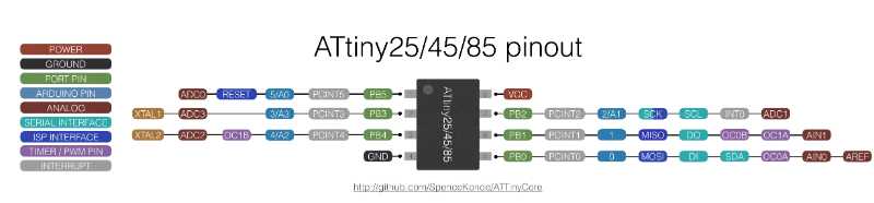
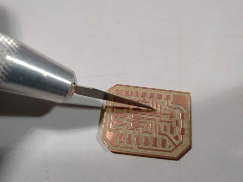
I redesigned the Neil's PCB and mill it. But first I had to find the Eagle library for the Sonar y download for DIYmodules.org

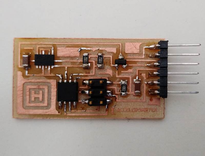
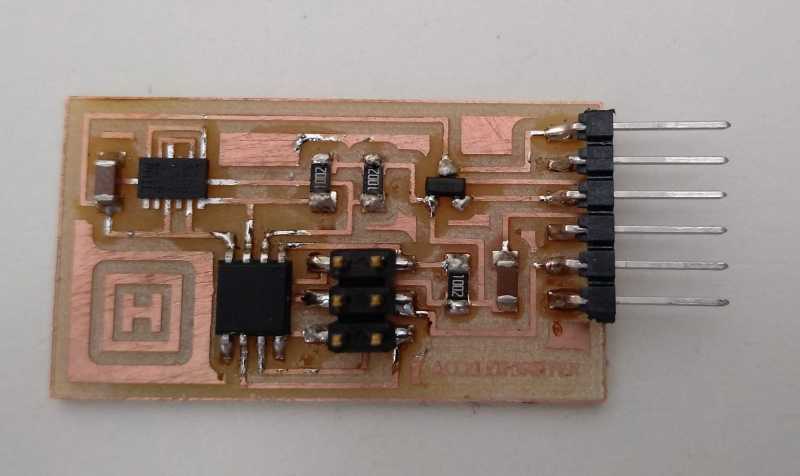
When I checked it looked fine so I sold the components and again it looks fine.
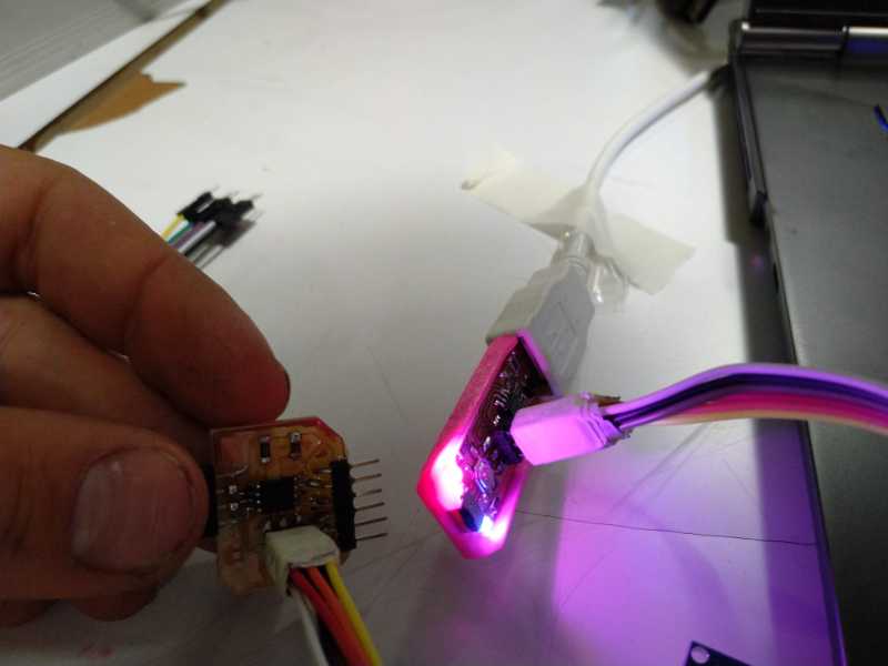
I checked the pins for arduino and programmed the board.
But... It wasn't as fine as I thought. The sonar started to be to hot to be working as it should be. I checked connections ans OMG. Look the first picture again.
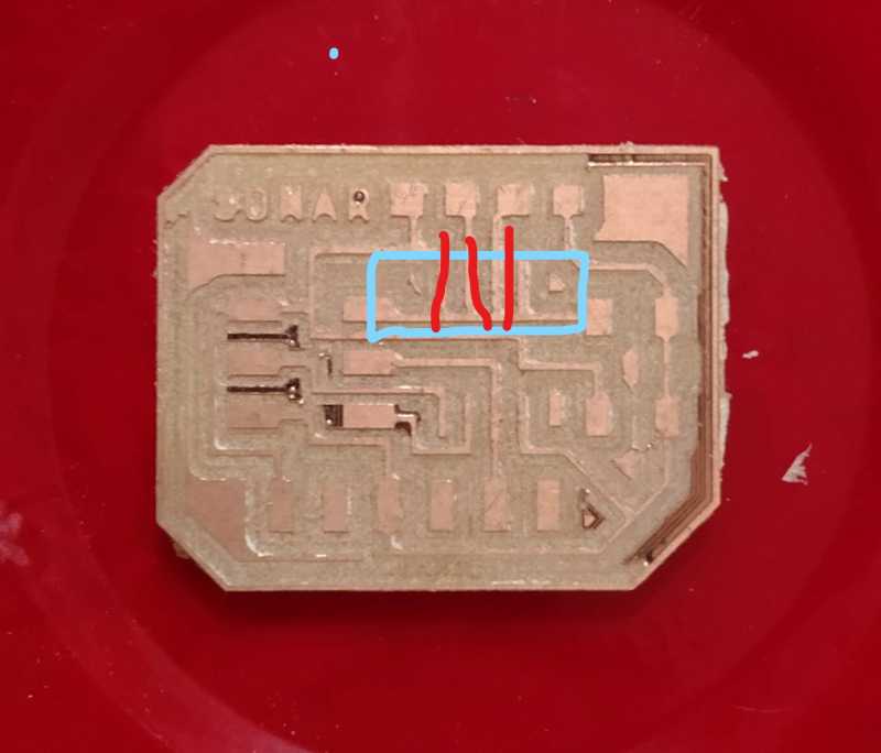
This pins shouldn't be connected to the VCC, I think that it's the reason why my sonar almost burned. I marked and wait to check it when the sonar is working. Well, as you see in the picture I had many others problems with Pcb board, as you can see.
Debugging
First I marked my sonar device as dead because It was very hot when I touched, I will tested later but It doesn't look well.
There is another odd thing, when I connect it to the programmer a led that should not be turn on is lighting... umm
and I can't burn the program... everything wrong the worst signal
Solutions
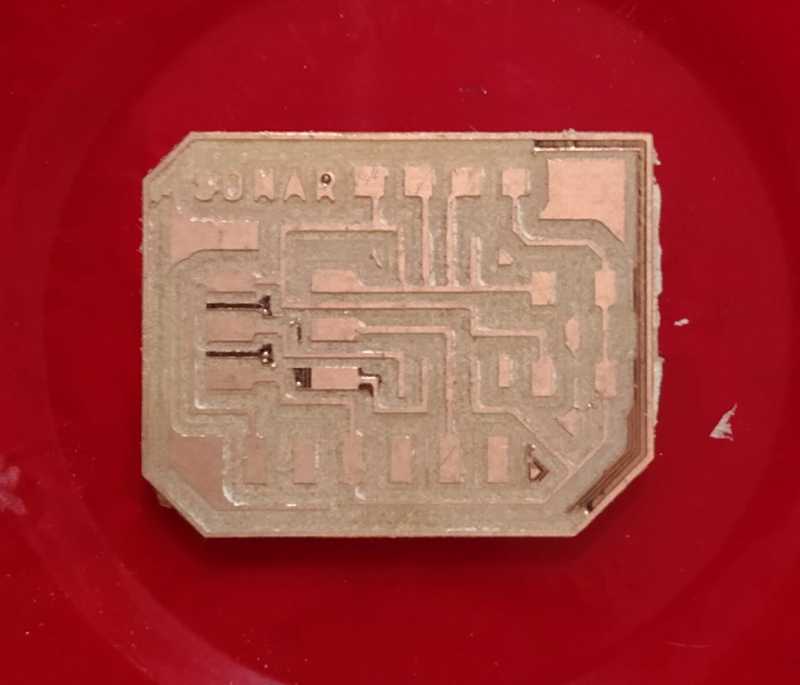
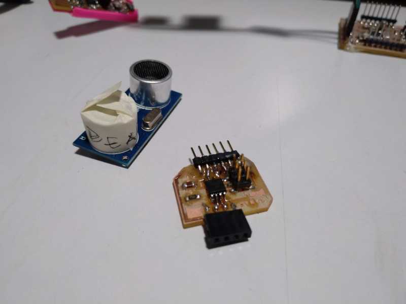
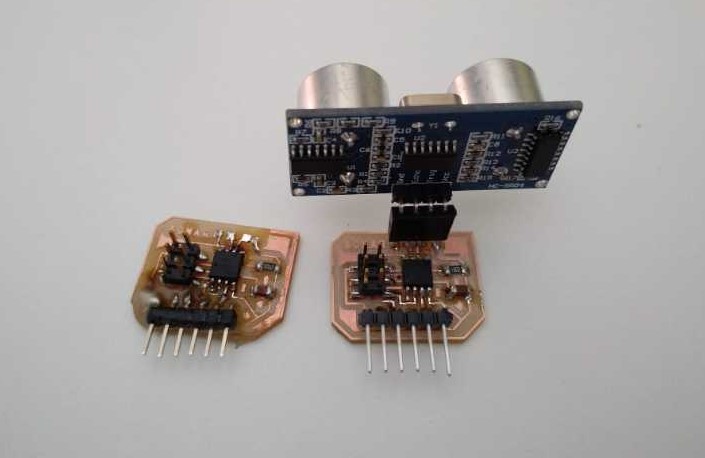
I made a new board and this time I cut the wrong connections and I was more careful checking everything.
Here you can see the old and the new one, it looks definitely better this time
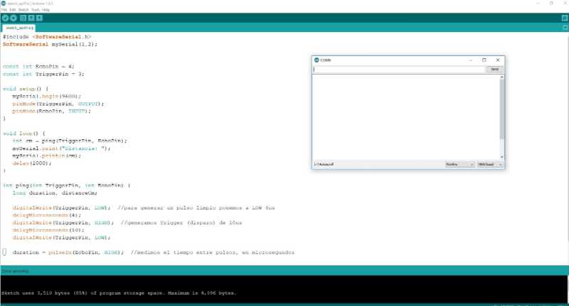
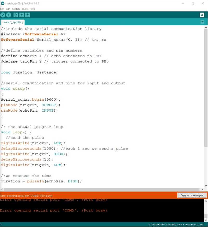
I tried the code again and I could upload the program without problem. This time I did not have any problem but when I connected to the computer it was impossible to get any data, not even the word "distance" which is should be seen in the screen the whole time. But if the board is ok the problems has to be in the code...
Finally thanks to Marta, my tutor, we found that it was a problem with the definition on the serial pins in my case the need to be like this:
SoftwareSerial mySerial(0, 2);
Now the program is working :)
Well I was worried about the sonar but following my schedule I milled the accelerometer with the hope that this time I would have more luck.
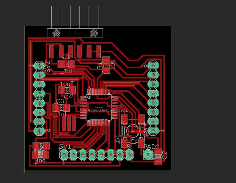
the first thing to do was to find the accelerometer library for Eagle. I finally found in ultra librarian a very cool webpage to find libraries and data sheet of almost any component.
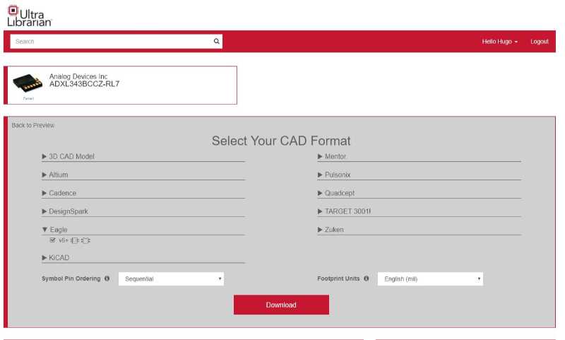
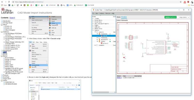
I load the component and start the design
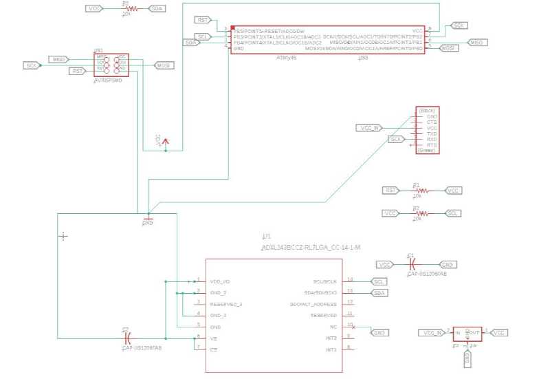
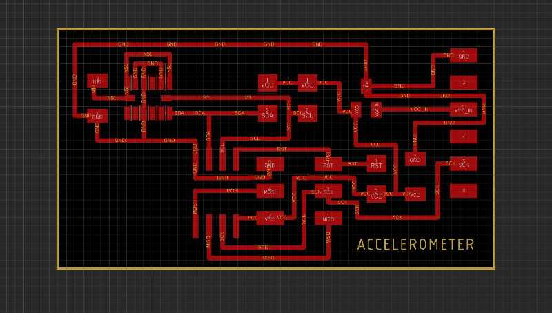
The design looks good so I mill it the pcb and check the result.
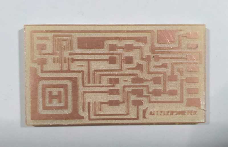
Again, I had the same problems programming the pcb... I really need to think how to debug this.
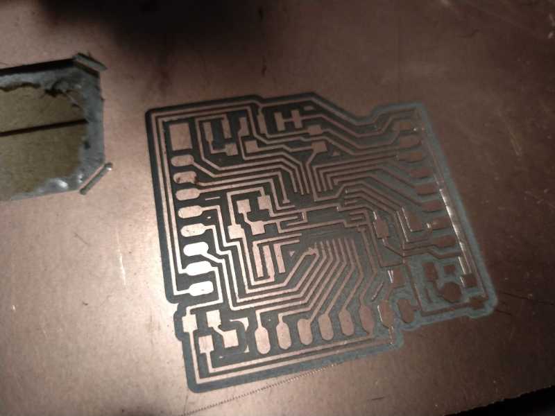
I've found the fabduino in the web I wanted to mill one to make easy to try different sensors before mill a special board. Also, the idea of create my own "arduino" sound fan. I download the files and make some modifications to make easier the milling process.
After checked the milling in fab modules I did some last repairs with photoshop, maybe not very professional but it works.
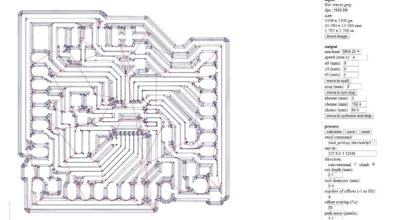

Here is the Fabduino finished before the border file.
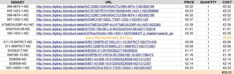
 Here is the Bom of materials necessary to make a fabduino kit v.4.0
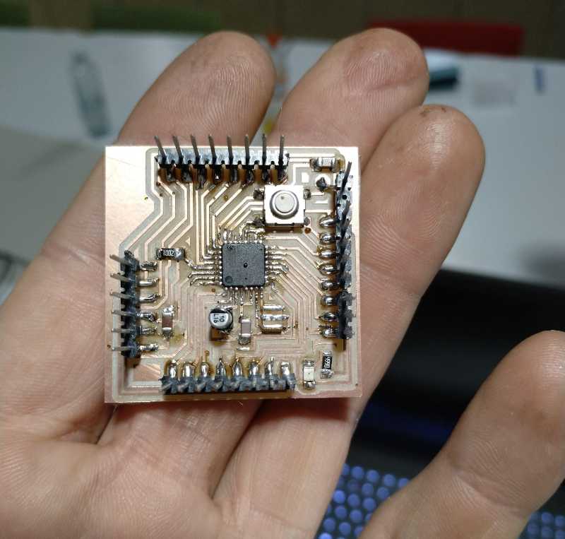
I was worried about the atmega328 but you only need patience and good pulse to finish it with a great look.
Now it's time to burn the downloader and the program. After this the fabkit can be programmed using the ftdi wire. To do the programming of the board it's important to use the correct pins. I've based on this tutorial
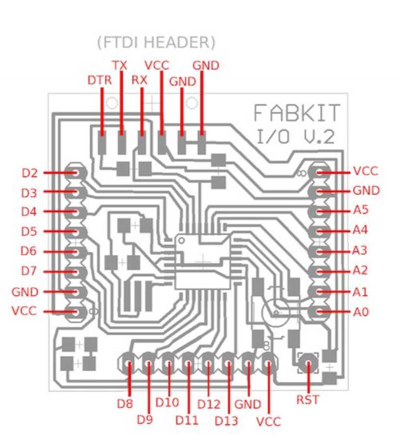
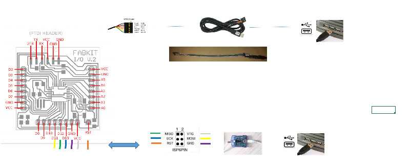
It's important to be careful with the pins so I marked the dupond cables with tape.
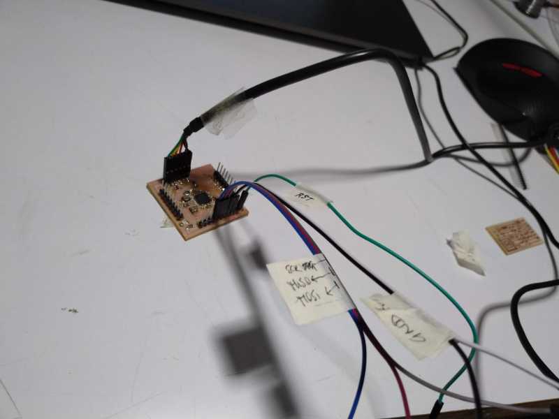
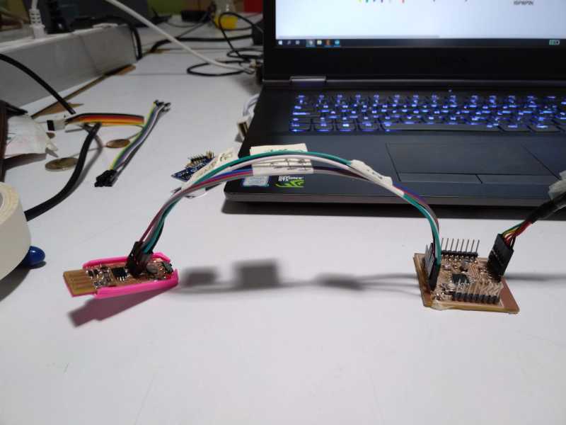
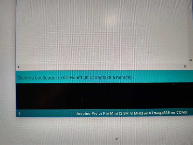
And here is the bootloading...
Problems programming the thing
I've been trying to program the fabkit using the USBISP or using the FTDI with no results at all... I've been trying different tutorials form other years but I can find the original source and the information is not very good. For example:
Here is a tutorial where it says that first you need to burn a special program in the fabkit to use the FTDI
But this one it doesn't said anything about a special program for the FTDI, if I follow the steps Arduino shows me an error message that basically says "The USBISP could not be found", something very obvious because I'm not using one, I'm using the FTID wire. It also says that I should use a power of 3.3V but my FTDI board with a switch it doesn't look like it's working at all.
The third one (here) looks better but the information with the FTDI is the same, altough it looks like he really got it.