ELECTRONICS PRODUCTION | WEEK 04
Group Assignment
A0 Link to group assignment.
You can see the group assignment hereThe first thing to do this week is test the milling Machine, in our case a ROLAND SRM-20. We have a example file that we download from fabacademy. The machine is prepared for milling with precision 0.01mm which is awesome. The area of milling is very small, 203 x 152 x 60 mm, but enough for milling boards and wax molds (we will use it for that in the future)
.jpg)
We have two types of drills:
- Flute Dia 1/32 (0.4mm). We will use this one for traces of the board
- Shank Dia 1/64 (3.18mm). We will use this one only for the border, to cut the board from the copper with phenolic paper.
.jpg)
.jpg)
To cut the example file we used which transforms a PNG file into a gcode that the machine can understand and cut. It's a very simple process that I will explain better later. But basically works by selecting the type of archive, the type of machine and the drill that you are going to use. When everything is ready the only thing left to do is find the origin (x,y,z zero) and put the machine to work.
.jpg)
.jpg)
Problems
We had some problems with the calibration of the bed. It wasn't corectly levelling. The diffecrence wasn't very big but it was more than enough for a machine as precise as this. After some tries we finally did a good example file.
.jpg)
.jpg)
.jpg)
Individual assigment
After the problems during the group assignment me and me classmates had the same problems in our individual assignment: We break many drills and the resulting board wasnn't good at all. When we where close to dessesperation a professor told us that the best way to have a great result in the milling was use a big drill to level the whole sacrifice board before start with the milling of the pcb boards.
We used the program CUT2D to level the whole board. Now the board is perfectly levelled and we can start to cut our own programmer.
.jpg)
.jpg)
.jpg)
.jpg)
Now we are ready to mill our pcb boards.
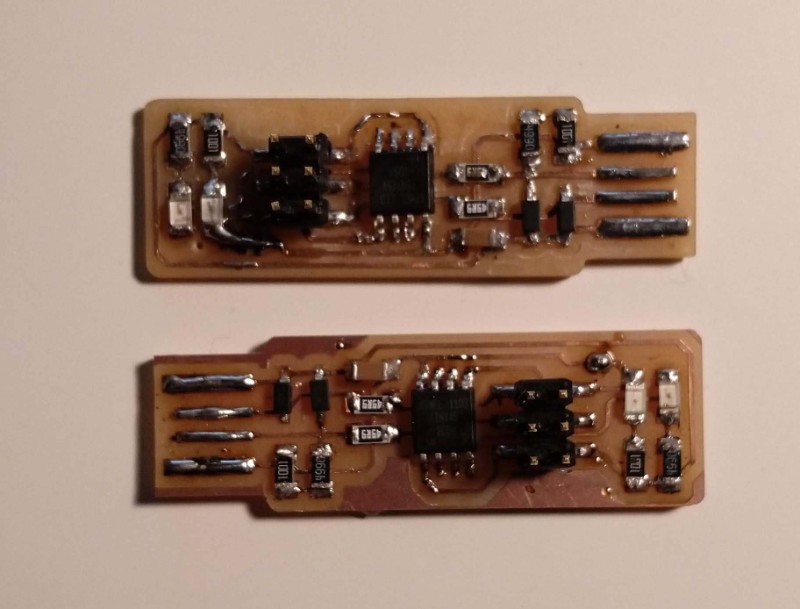
I picked the FabTinyISP because is easy to soldering and there were many tutorials from other years. To produce it I follow the instructions in the Fabacademy Tutorialwhich is based on Zarec's version of the AVR ISP programmer.
First thing to do is download the PNGs from the web and use them with fab modules. Here you select the type of file to upload (in mi case a PNG file), the the output format (Rolland mill) and the process (traces 1/64). After select all this options you have to select the machine (SRM-20 for us) and then it's posible to change some values. It's not necessary to do any change but I change the origin (because I was going to change it in the rolland machine) and the speed, from 4mm/s to 3mm/s Although it is possible to change it again using the machine software.
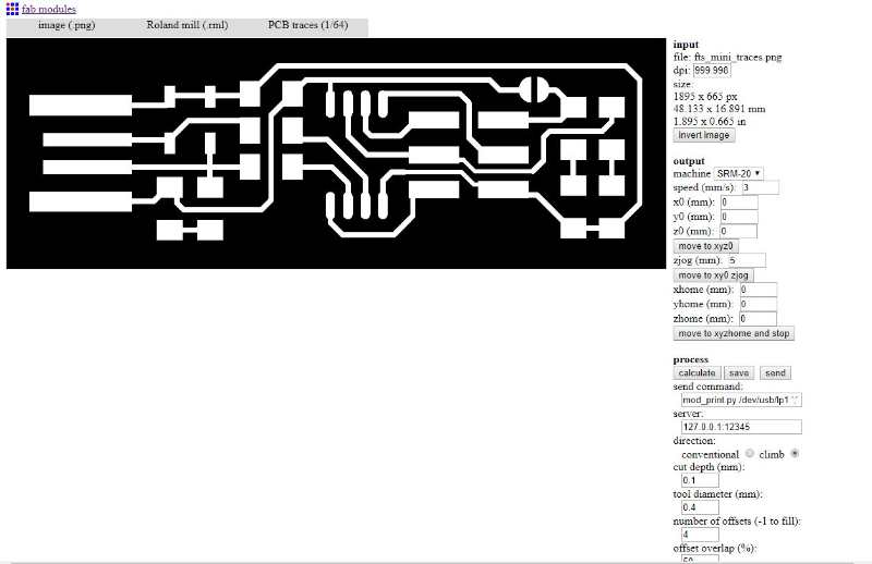
Now it's time to press calculate and wait
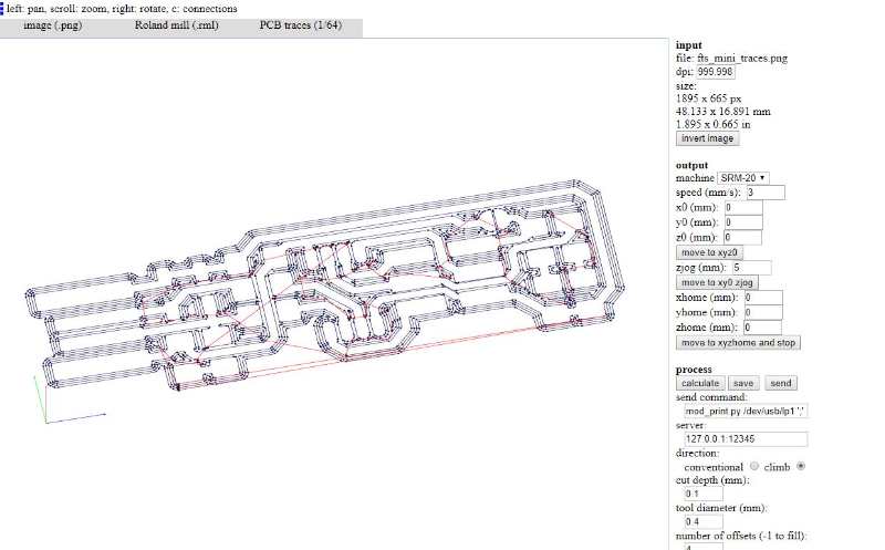
The result is a file with the routes and coordinates for the milling machine. I saved the file and use put it in the srm20 software to mill my pcb boards. I did the same with the border file, but this time using the process "border".
Although we all prepared our pcb boards individually we decided (my classmates and I) to mill them at the same time. The reason to do it like this is it was that we didn't have enough time to try them individually, after many tries we expend most of our time breaking drill. So we thought that it was interesting to put all out pcbs in the same file to save some time.
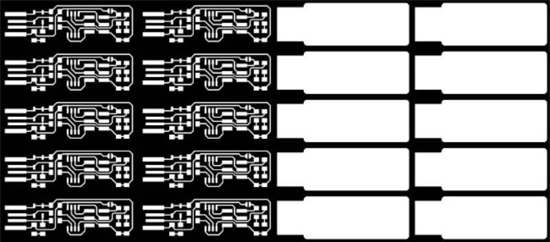
...and, well, it worked...
.jpg)
With the board ready is time to sold all the components. For a FabTiny USB you need all these things:
- 1x ATtiny45 or ATtiny85
- 2x 1kΩ resistors
- 2x 499Ω resistors
- 2x 49Ω resistors
- 2x 3.3v zener diodes
- 1x red LED
- 1x green LED
- 2x 100nF capacitor
- 1x 2x3 pin header
It also necessary to have this tools:
- a tin solder
- tin with flux
- a multimeter to check connections
- tweezers
- double face tape
- "Chupón" a tool to take off tin
.jpg)
I put the PCB board in the top of the tape. It makes easy to control or move the board without touch it. The soldering went fine, I had experience with sodering but not for boards, only with steal wires, but it made me be more efficient.
.jpg)
And here it is!
.jpg)
It is good to do a visual check and see if the tin looks shiny. It also very recommended to do the same but using the multimeter to check continuity.
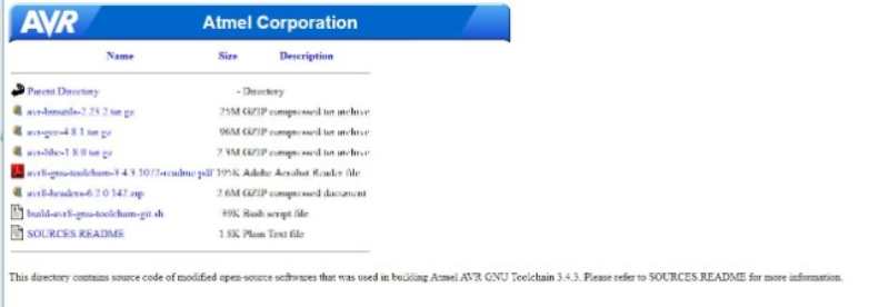
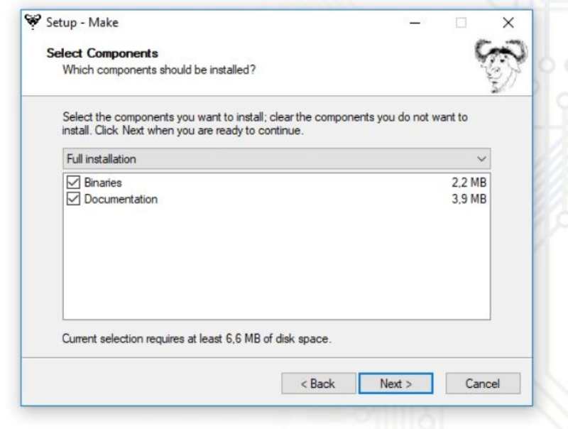
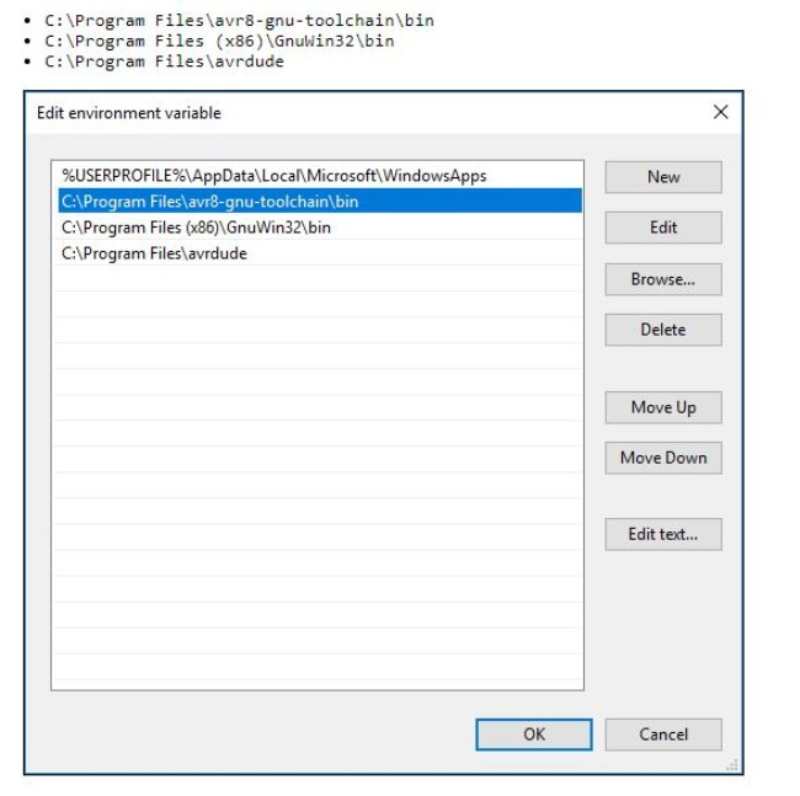
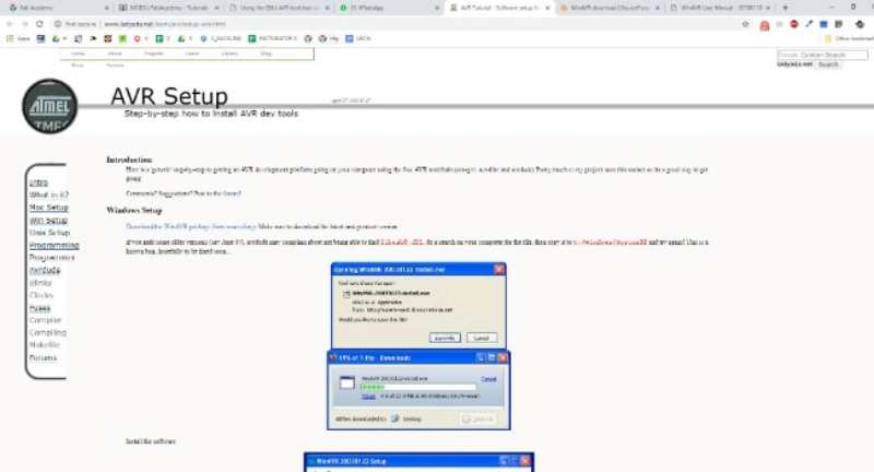
The best advice that I can give about programming your programmer with windows is don't do it. The process is very slow and you need to install many programs,libraries and who knows what to achieve something. I don't wan to extend too much with this. Basically I followed the instructions in the tutorial for windows and install everything that it was necessary. It GNU AVR chain on windows 10
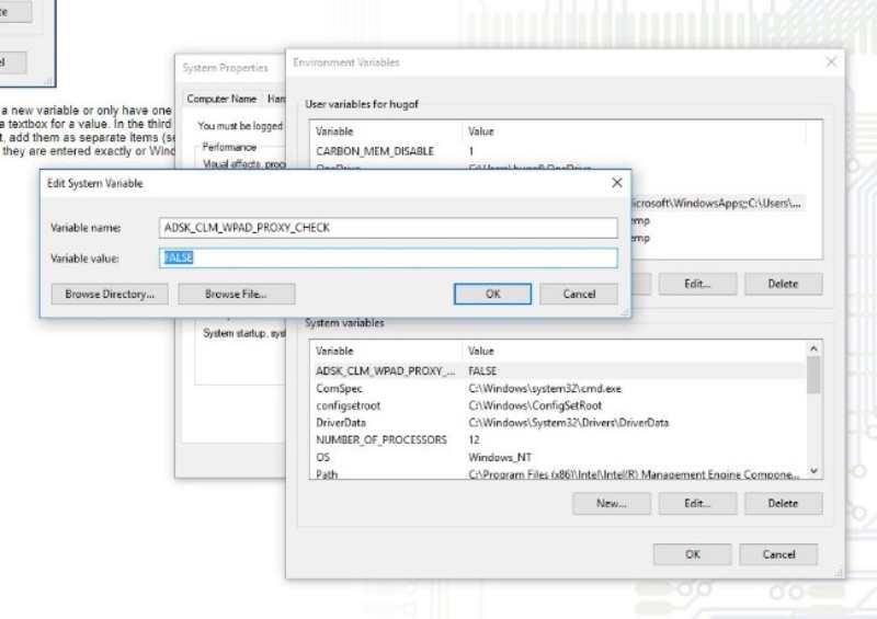
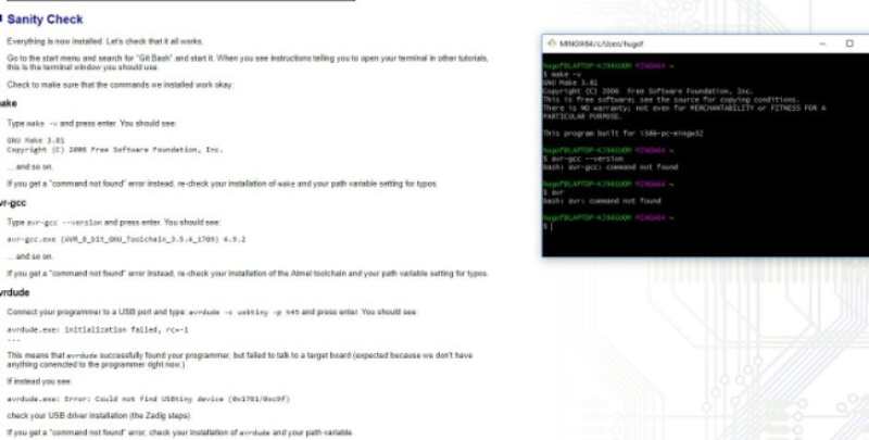
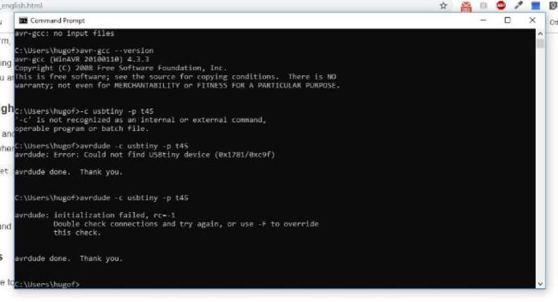
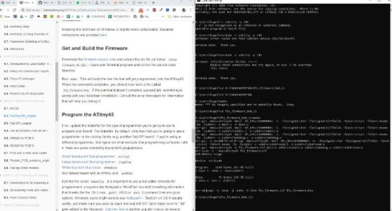
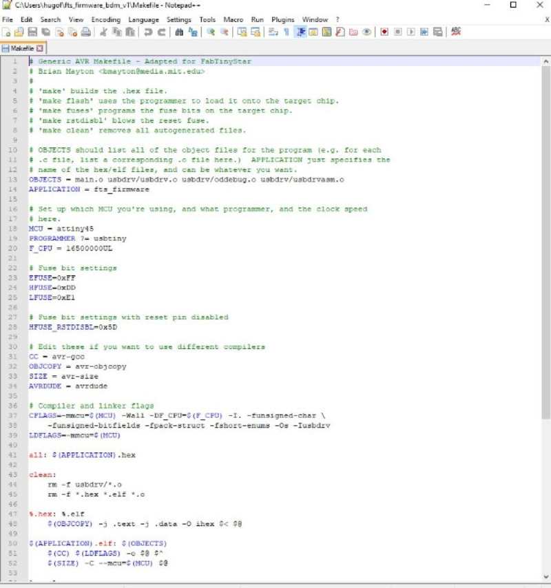
When everything is installed and check it's time to get and build the firmware. Which it can be made using the console. (windows's CMD). I download and unzip the firmware source code. The idea is to get a Make file.
With the Make file ready it's time to programs the programmer. So I plugged it in the computer and connected to another programmer. It's important to connect them right (careful with the orientation of the pins)
.jpg)
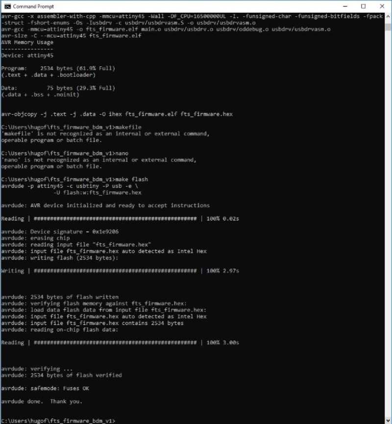
Now it's time to do three commands and do them right. The commands are this:
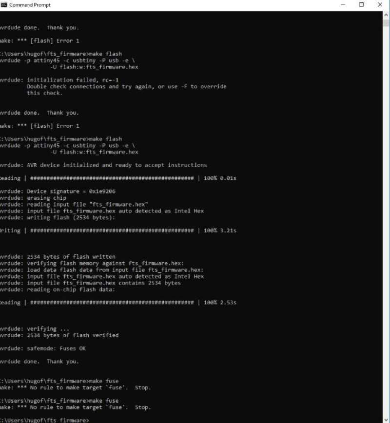
- Make Flash This will erase the target chip and program the flash memory with the content of the hex file.
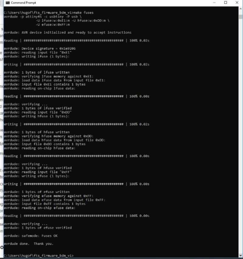
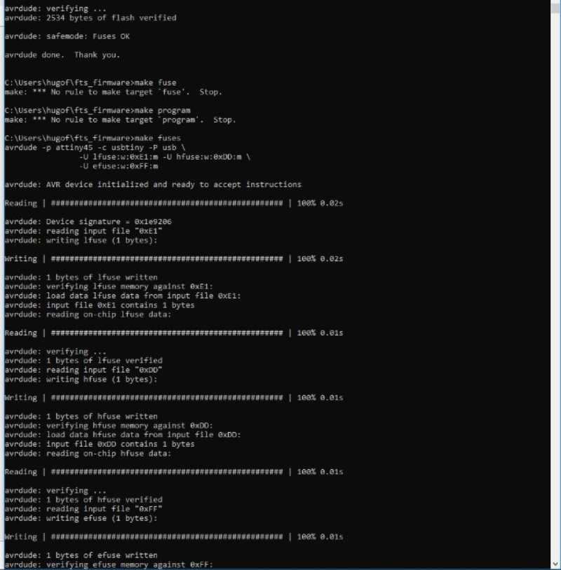
- Make Fuses To set the microcontroller fuses and get its clock source from.
- After fuses is veeeryyyy important to check that the programmer works and the computer recognize it as a usbtiny. Only after this it's possible to do the last step, which can't be undone
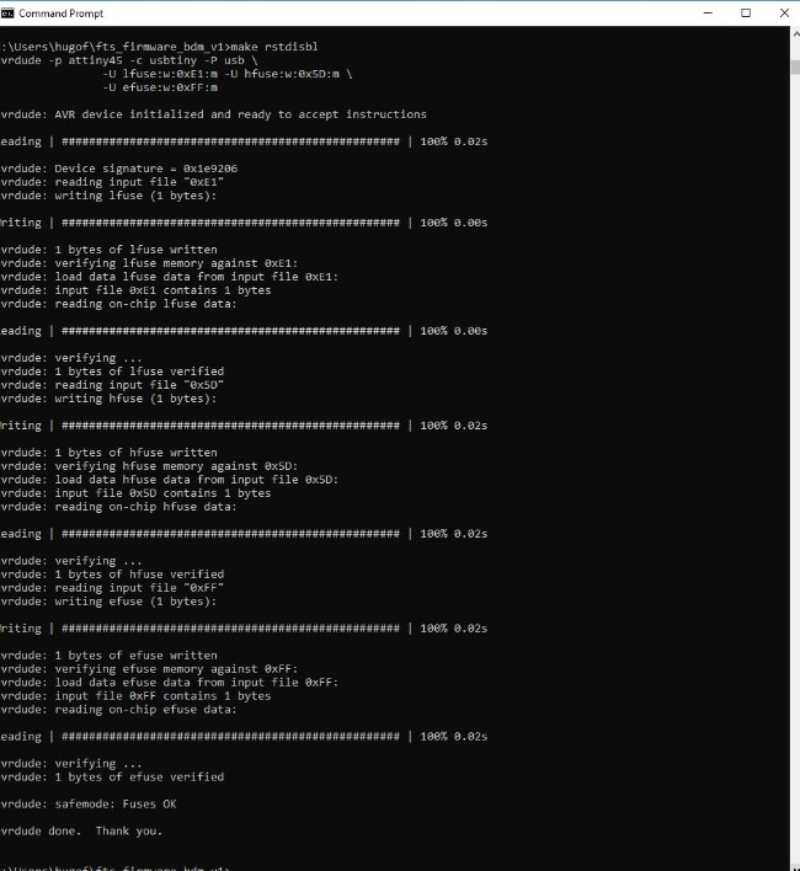
- Make rstdisbl> This will blow the reset fuse and turn the usbtiny into a programmer.
- The last step should be disconnect the VCC from the Vprog pin by removing the bridge on the solder jumper.
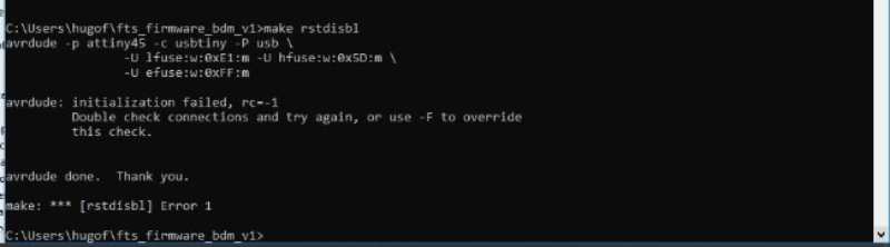
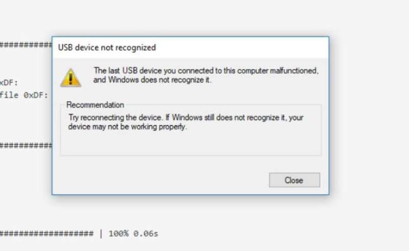
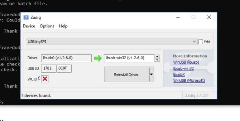
At the end I had this problem. why? Well I run "make rstdibl" without check if the computer recognize my programmer and ended with something not very useful :( Well, now i have a big problem to fix.
This was my first real problem in fab academy, one big enough to don't finish the assignment so I became crazy with it. At the beginning I didn't know why it wasn't working, the tutorial was a little confuse about it and my tutor didn't know why it wasn't working. I couldn't do make fuses o make flash and the programmer wasn't respond to anything. Even more, no one in Madrid or Leon (our regional node) had the programmer working so it was a real mess.
At some point I decided to take off the attiny45 and sold a new one but it was very difficult (I didn't know the trick then) so I made another one, but this time I wasn't very careful with the tin and it was many bad connections. So I got back to the first one take off the attiny using a heat gun and make the process again. This time I made some changes:
First I connected my programmer to another computer or to a cellular charger so the computer doesn't mix the ports.
Secondly I check the connection with the usb port before make fuses.
Done! At the last minute of the last day I finally finished the ISP programmer and fix the problems with it.