Student in charge of documentation in this group assignment: Edu Segovia
General considerations and values about PCB production process: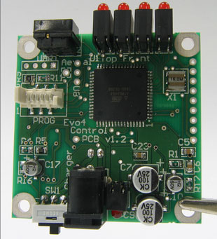
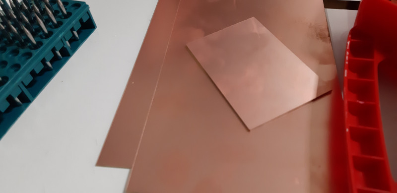
For this assignment we used FR-1 board.
FR-1 is a hard, flat material that consists of a thin layer of copper over a non-conductive phenolic resin (…) primarily used for making circuit boards. The thin copper layer can be milled or etched away, leaving traces to which electronic components can be soldered. (Source)
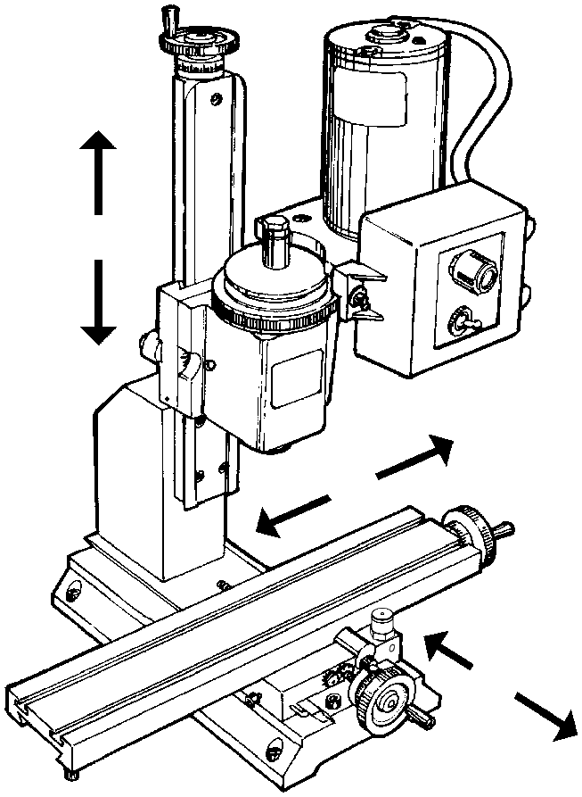
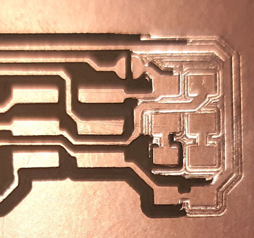
There was a design to be made for testing the desktop milling machine:
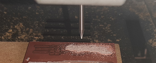
The idea with this design is to test the milling precision. We used a 0.4 mm (1/64’‘) thickness mill.
These were the followed steps to do the assignment:
Prepare desktop milling machine file(s) > We used fabmodules.org to generate the g-code

Prepare materials in the bed of the desktop milling machine > Used doubled faced tape. Recommended to clean and put the board in the center of the bed to reduce milling depth differences
Prepare the machine (remember that opened machine door limits some functions for security and also can freeze the VPanel software):
Put and fix (just enough) g-code programmed mill into the machine rotor (0.4 mm (1/64’‘) thickness). Check the straight rotation by testing ‘in the air’ from VPanel
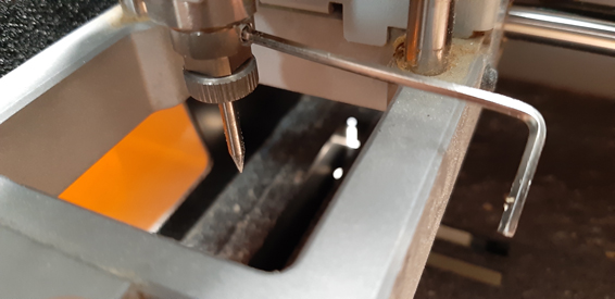
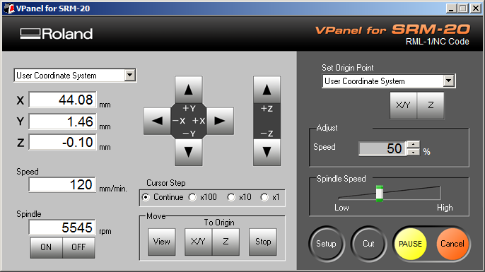
Calibrate (x, y, z) axes to set the job origin > Used Roland provided VPanel software
Retire the mill in Z axis from the board (use +Z VPanel button in ‘continue’ mode)
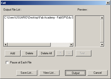
Load file to the desktop milling machine > Used Roland provided VPanel software
(WARNING: pressing ‘Output’ button will begin the job)
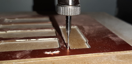
Test operation > Watch/Hear if mill slashes the board
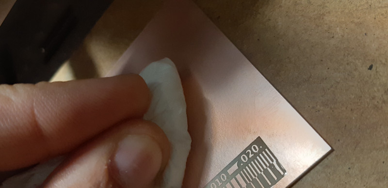
Check operation and results > Use VIEW button to bring closer the machine’s bed. Check mill tip and material depth worn (copper layer must be completely removed at the design black zones)
Readjust (in needed) machine settings/material/design/laser machine file(s) > If material or mill are changed, machine’s preparation must be done again
Clean cutting dust on the machine and parts >
Secure the workspace (turn-off the machine, close door…)
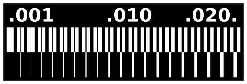
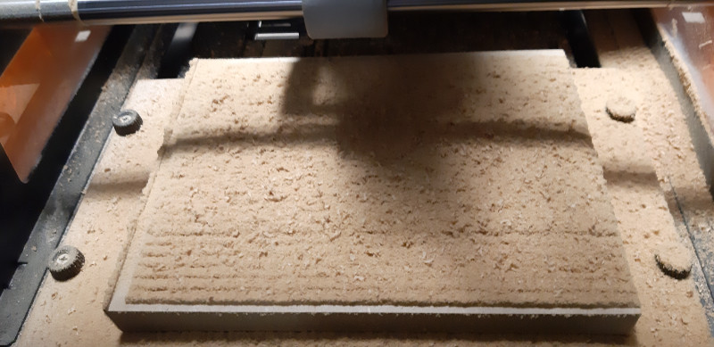
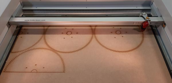
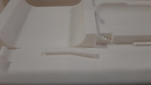
These are the 0.4 mm (1/64’‘) mill tracing test results of desktop milling machine:
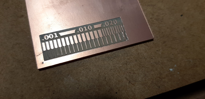
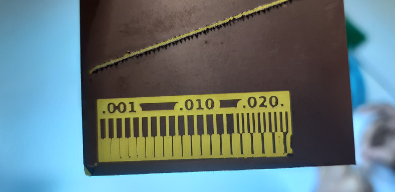
Resolution starts to get lost at 0.03 point and down, and functional limit is lost at 0.01.
Roland monoFab SRM-20 desktop milling machine on 1.7 mm FR-1 board reports these main pros/cons conclusions:
PROS
CONS
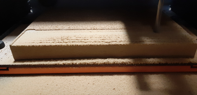
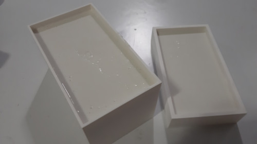
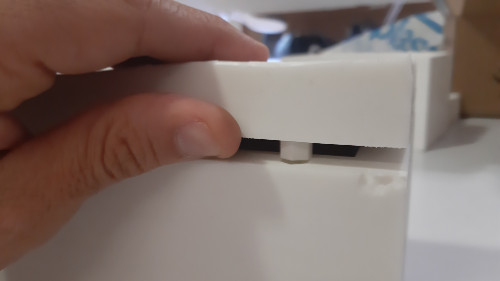
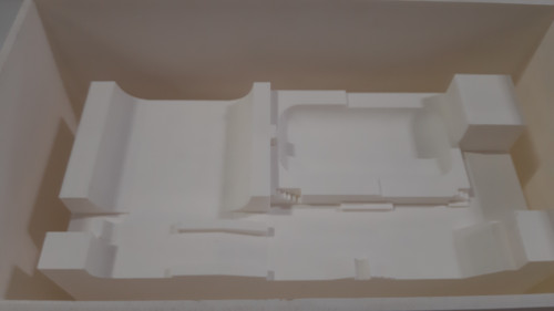
The way the machine works needs a bed well calibrated to avoid Z distance differences, which would return some parts more worn than others or some parts even without being worn.
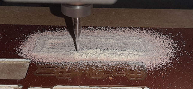
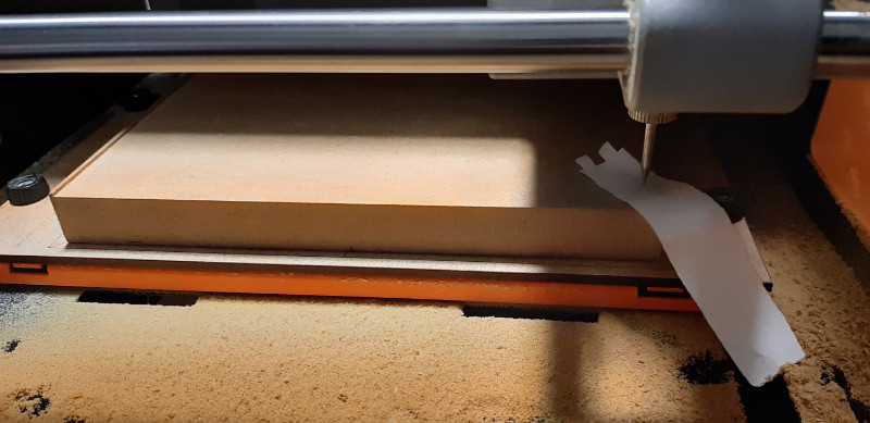
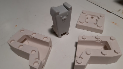
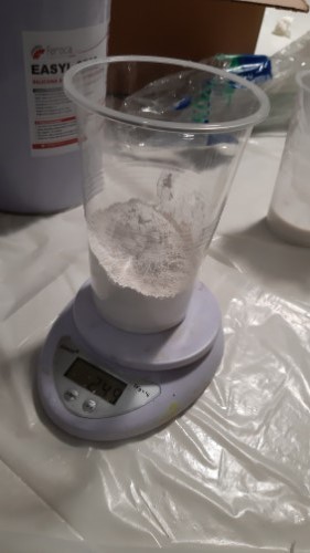
All non machine bed-parts were removed and replaced with ones.
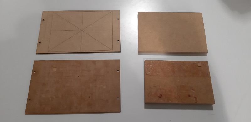
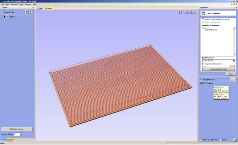
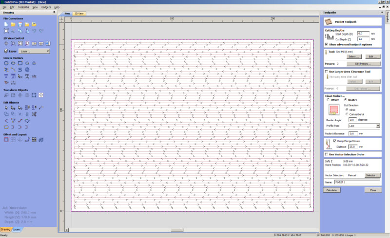
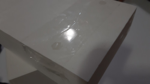
Then, a 1 mm cut was made on the material to ensure the same Z distance on any part of the bed. It was done with a bigger mill in two Z=-0.5 mm passes. The g-code was generated in Cut2D Pro.
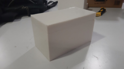
This is the result of a new well calibrated bed-machine in where to put the material for PCB production.
Student in charge of documentation in this group assignment: Hugo F. García
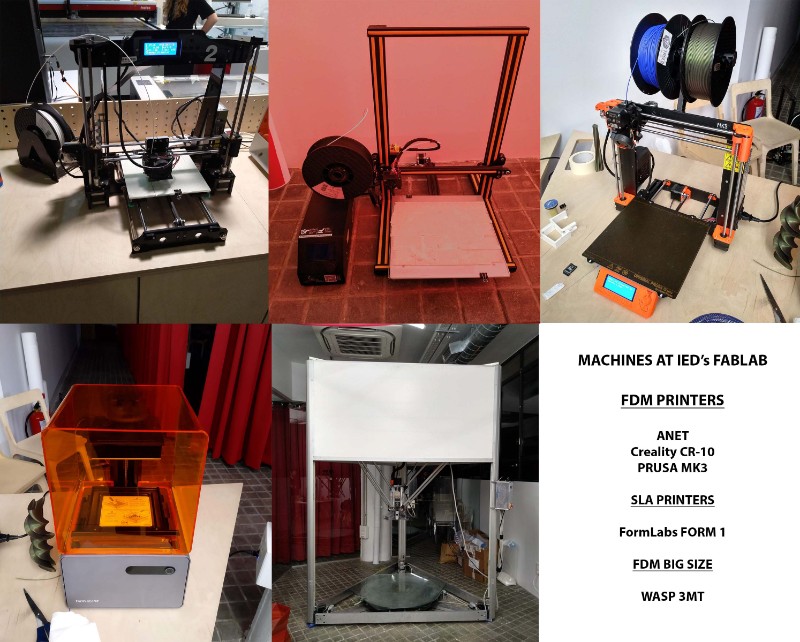
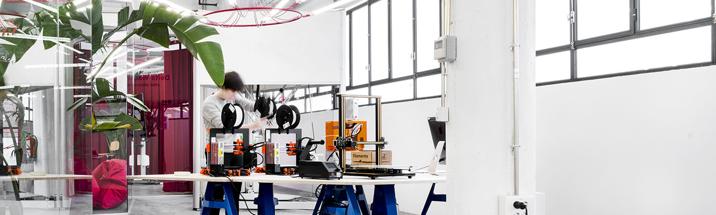
At the lab we have many different kind of machines. This week we tried to use all of them but we focused on two of them ( the Prusa MK3 and the Creality CR_10) to try the quality, time and funcionality. But first we want to characterize our Machines.
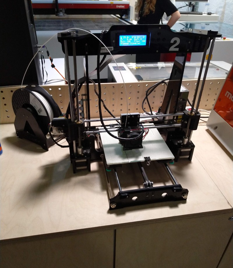
This is oldest machines in the Fablab the quality is not very good. The bed Levelling is manual and the personel of the FabLab has made somo dirty repairs to make them worked.
Characteristics
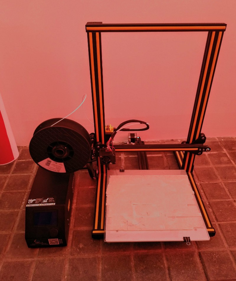
The Creality CR-10 is a much better machine than the Anet, but the printings have some problems if you don't take care of the printer regularly. Maintance is very important to ensure a good quality. The bed levelling is also manual and the the firmware is closed. There are some kits to install a automatic levelling system but it's risky because you can end without a firmware in the machine.
Characteristics
The advantages of this printer are the printing volume:
300x300x400mm, there are other models from the same family with
biggers sizes (500x500x500mm), is easy to install and the
quality can be very good if you have patience.
As disvantadges the preparing of the machine for printing can be
very tedious and the time to preheat the bed is really long.
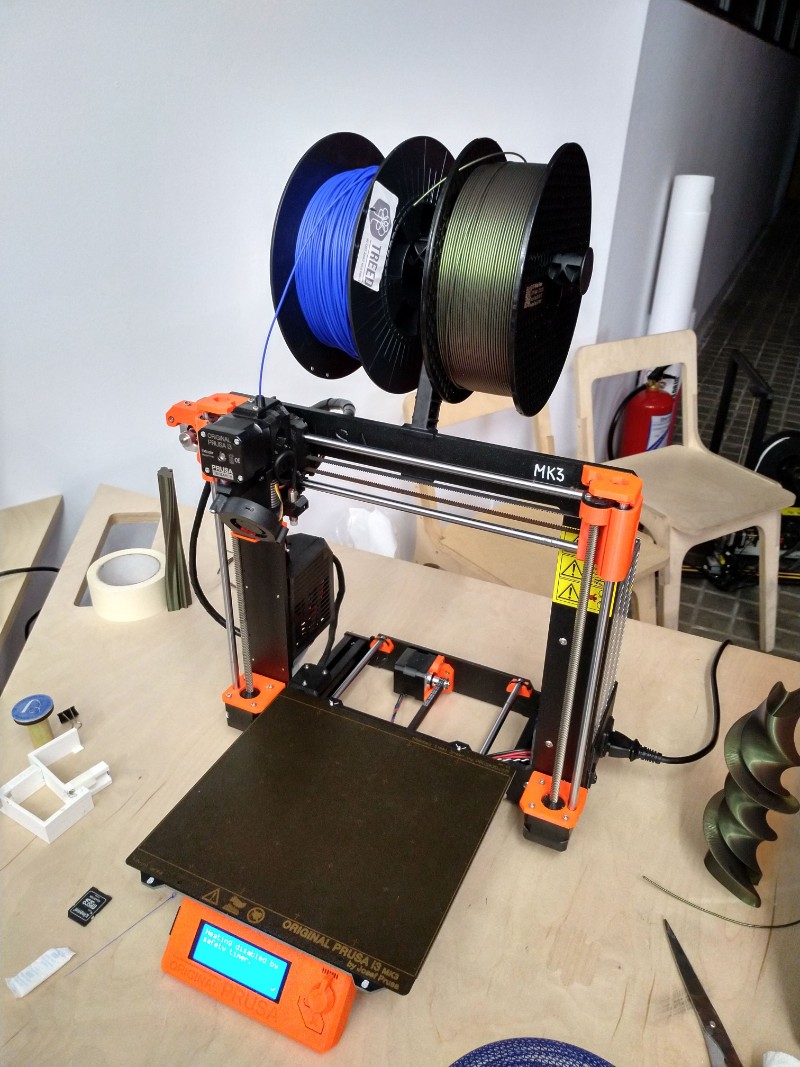
There are two types of Prusa in the Lab, the MK2 and the MK3. This is an excelent printer, very precise and easy to use (you only need to load the file and press a button to start the whole process). the bed is specially remarkable, it makes very easy to take off the printed pieces and doesn't need any extra solutions to fix the piece as masking tape or glue.
Characteristics
The advantages of this printer are many and it's the winner of the
all FDM machines in the lab. You can have confience in the
result and print faster and with better quality than in the
other machines. The Firmware is also very useful and have many
features that makes easier processes like change the filament
or levelling the bed (it's a completely automatice process).
As disvantadges the build volume is not so big as the one in the
cr-10.
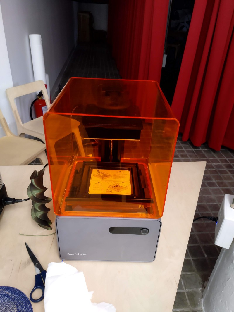
This is a very different kind of printing machine. Instead of using
filament it prints with resin and light.
The advantages are the quality of the pieces, which is much much
more than the quality of a FDM printer, the software is smarter
than any other and the precalculation of the final time is
really good.
As disvantadges the size is very small and the postprocessing of the
pieces is long and dirty; when the machine has finished is
necessary to clean and curate the resin with care and patience.
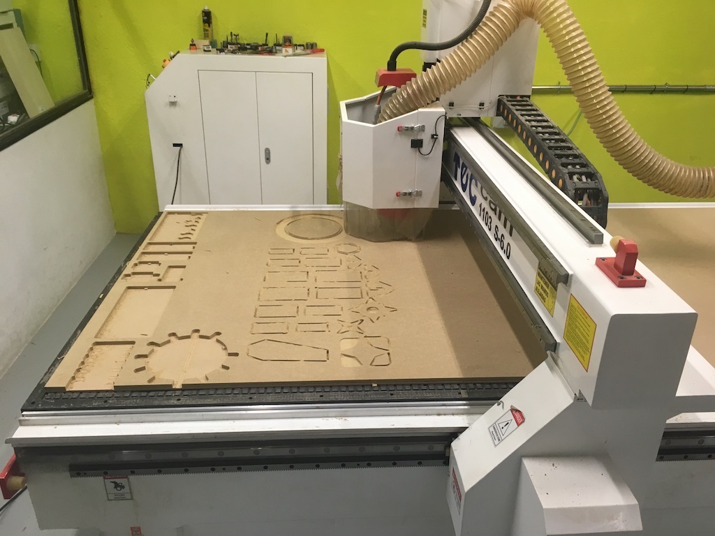
The same but bigger. In this case is a delta machine with a printable area of 1m2. It doesn't work with filament, instead it's necessary to use pellets. The nozzle is very big and the width of each line is 5mm. Right know it can be used only to print surface without supports. the supports are very difficult to take off and the reason to don't create solid objects is the weight and time to create them.
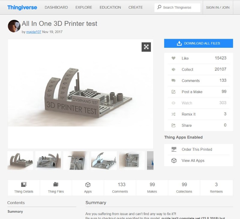
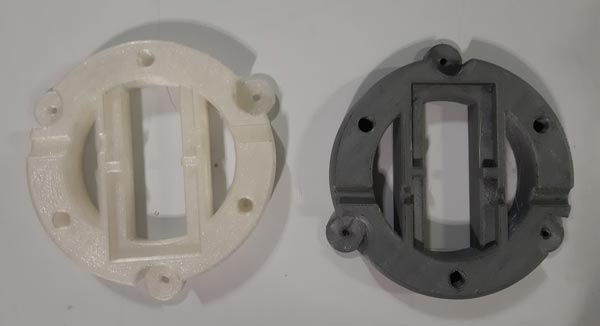
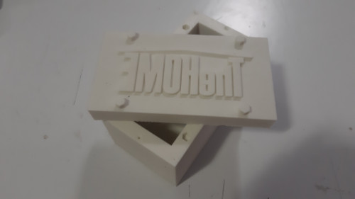
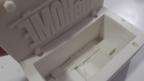
we printed the same filed in both machines to see the quality that they can get. The archive that we used is a "torture test" a special piece designed to force the machine and thest things like definition, overhang and precision
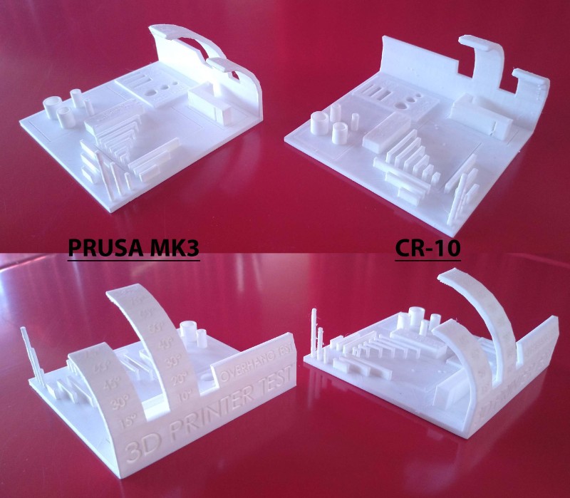
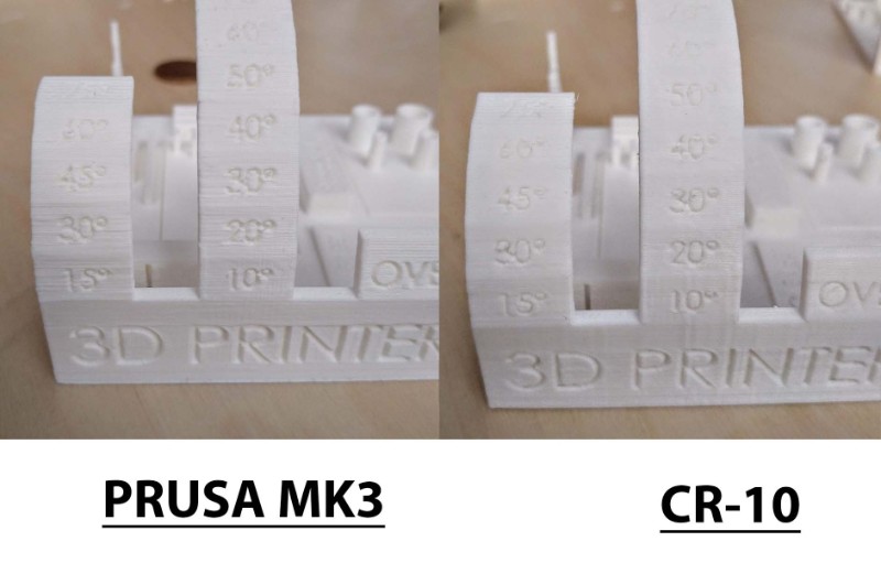
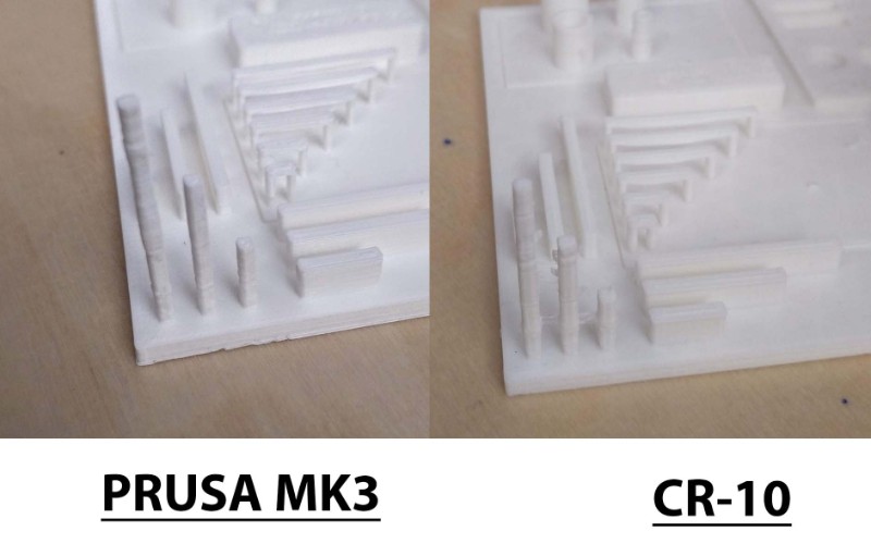
The results shows a better quality of the Prusa Model, the surfaces are more continuous and there aren't dots of filament out of them. the letters are more legible and the only thing that it's worst is the overhang; the print starts to have problems of overhang from 60º to 80º.
he results shows a better quality of the Prusa Model, the surfaces are more continuous and there aren't dots of filament out of them. the letters are more legible and the only thing that it's worst is the overhang; the print starts to have problems of overhang from 60º to 80º.

In the other hand the cr-10 has a better behavior in the overhang and it's almost perfect even at 80 degress, the towers are also more straight and uniform but the dots and lines in the surface create many little mistakes that makes the piece look worst than in the MK3.

Student in charge of documentation in this group assignment: Abhay Prahaladhan
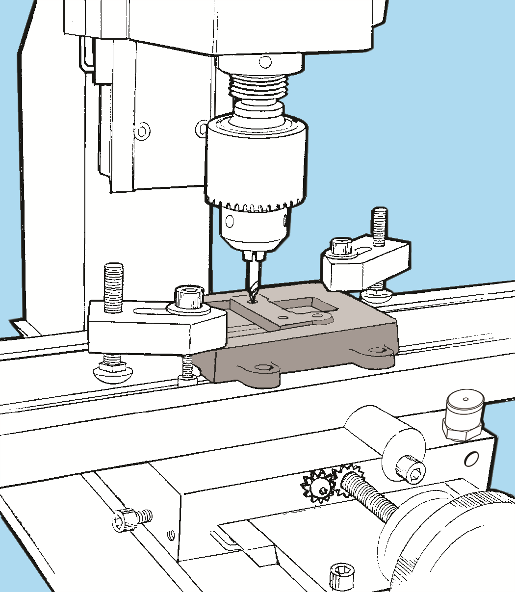
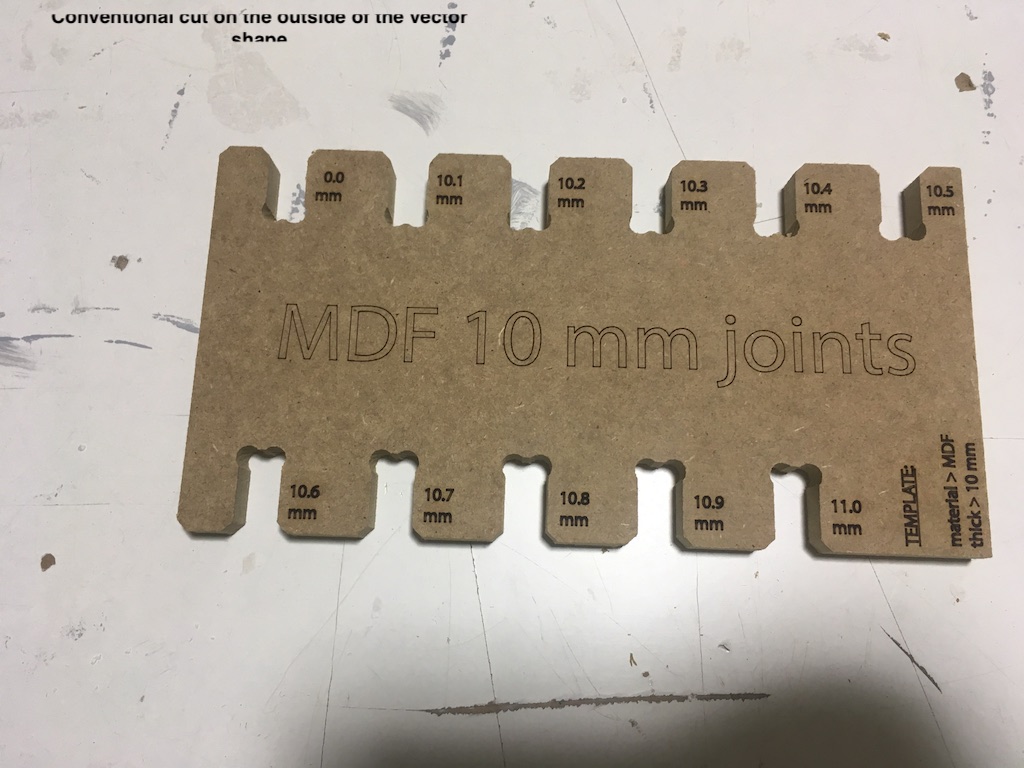
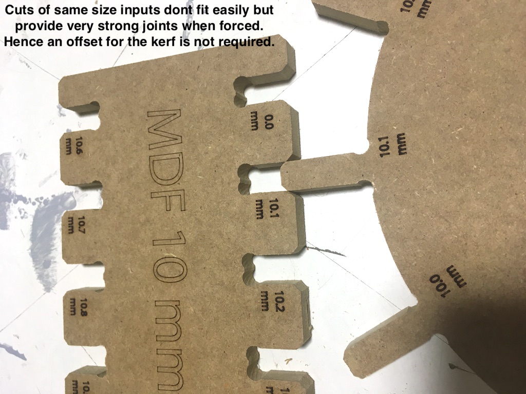
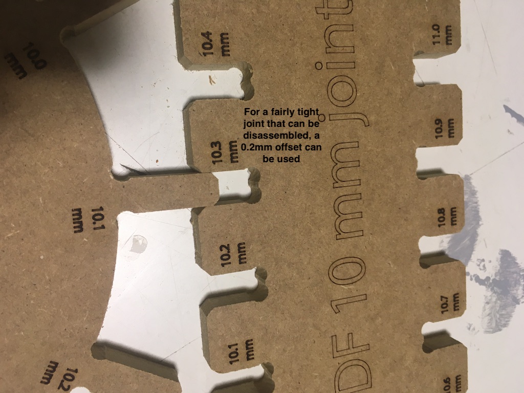
Listen to the sound from the machine Always wear glasses, shoes, fitting clothes and gloves Ensure cut pieces do not block path of mill.
Mills have different movement patterns: Down cuts, centre cuts, up cuts shallow cuts with down cut or deep cuts with up cuts Hybrid mills can cut both. Upcut with HDPE is beautiful unlike wood where we would use a down cut.
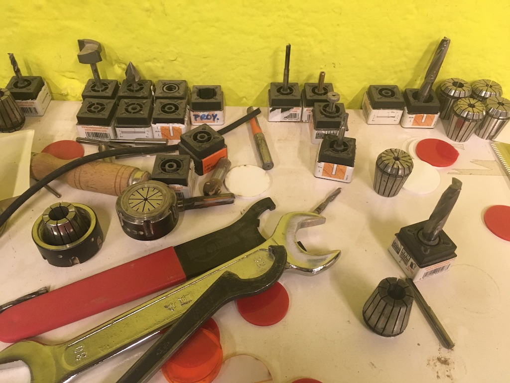
Flat vs ball end mill bits. Ball end for smoother finishes and in curved projects. Flat end gives more accurate cuts in flat surface with 3 axis movement and to remove debris
MDF & its expensive cousin- Valchromat OSB- oriented strand board- to look into HDPE- Cuts well and flexes well Garolite- PCB material safe material to work with carbon fiber Aluminium composite panel
Listen to the sound of the machine Chip load: amount of wood each spin take out: between one and ten thousands of an inch Work depth should ideally be= Diameter of tool Stepover= half or more of tool diameter for cleaner cuts
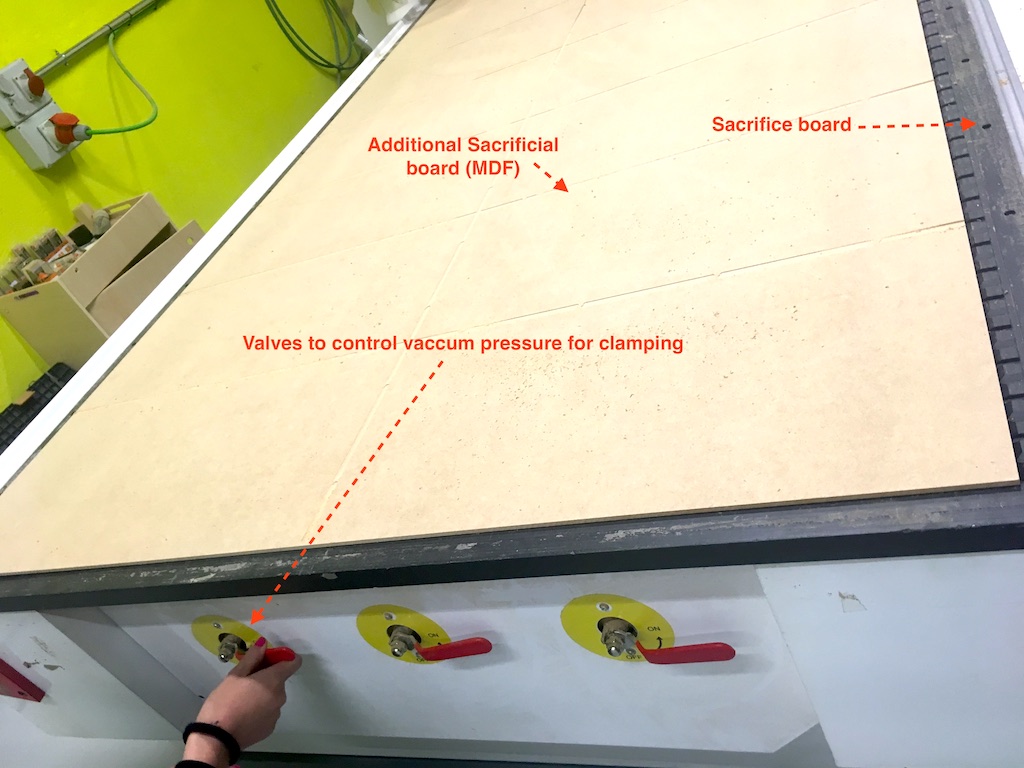
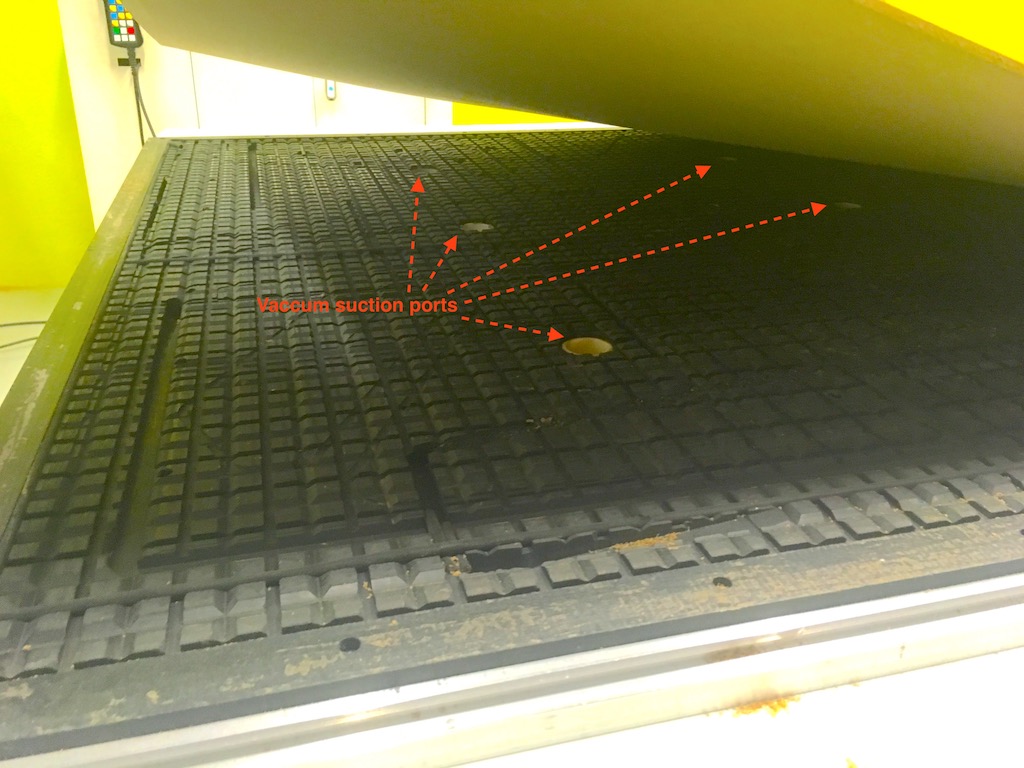
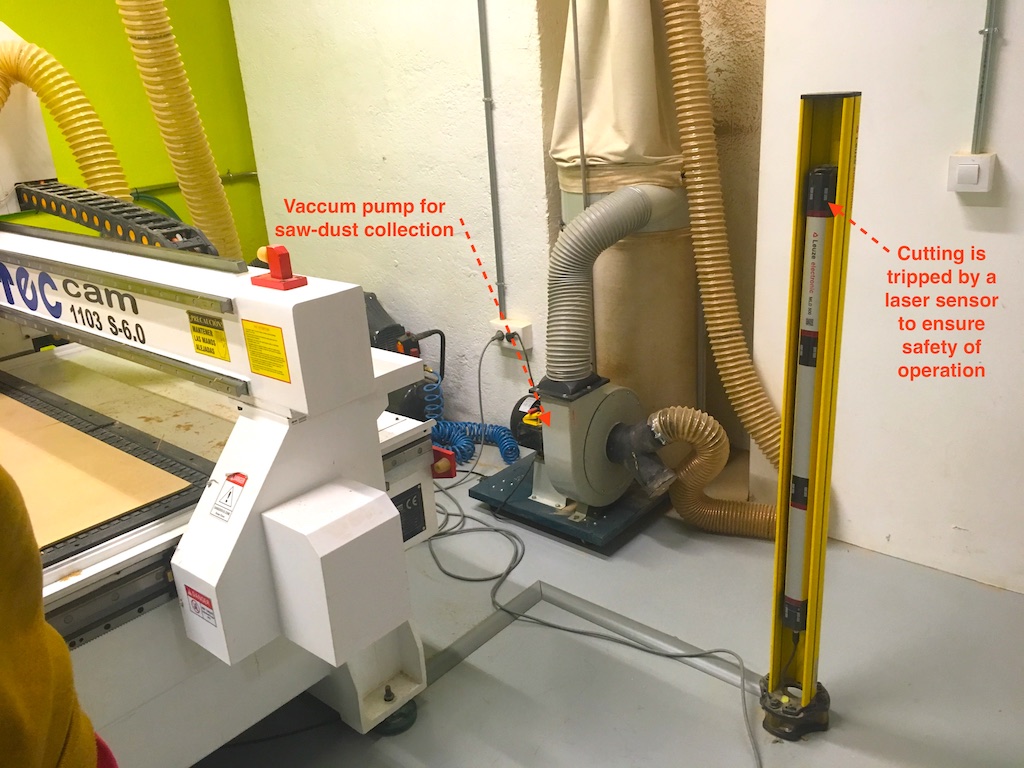
Wood screws to hold stock board into sacrifice board or glue guns Our CNC has vacuum suction to help hold the board in place while cutting.
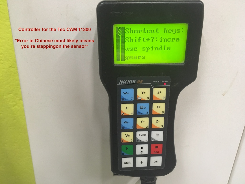
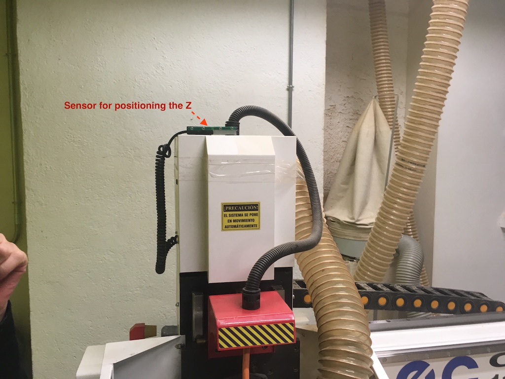
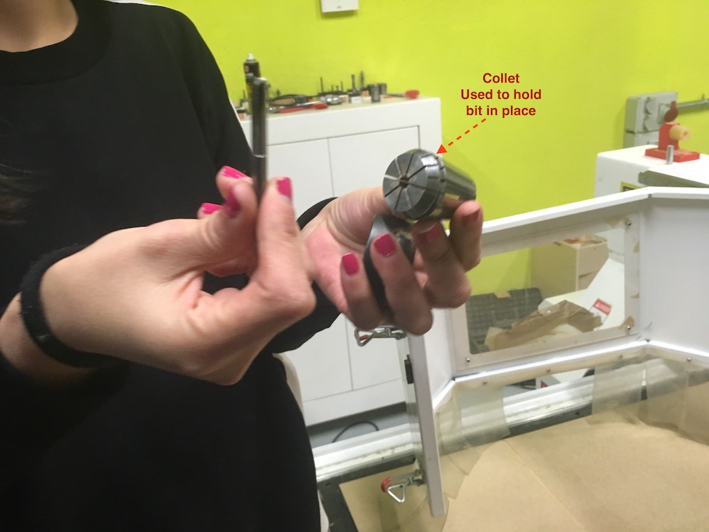
X and Y home can be calibrated but is normally in the bottom left of the bed. Z axis calibration can be done using a sensor placed on the material that we are cutting.
Student in charge of documentation in this group assignment: Rodrigo Gamboa
This week's group assignment is about testing different boards we have, that are built with different architectures than the AVR, like the ATtiny microcontrollers and Arduinos that use ATMega.
To accomplish this we had:
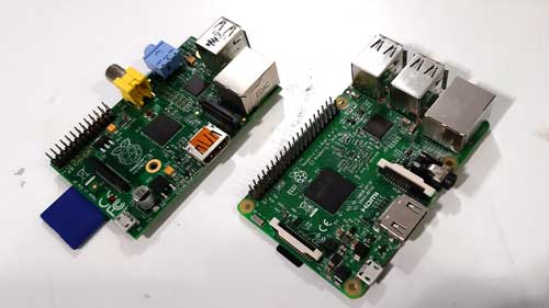
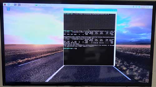
One idea suggested by our instructor, Marta Verde, was to run a Processing sketch on a Raspberry Pi 1 and a Raspberry Pi 3 to compare the performance of this two versions.
First we made the set up for the Raspberry Pi 3 by downloading an installing Raspbian and copying it into a sd card
Then we connected the next components to the Raspberry:
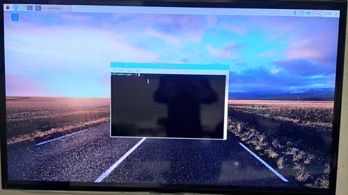
After setting up the Raspberry and turn it on, it immediately showed the desktop, as the Raspbian version we installed was "Raspbian Stretch with desktop and recommended software".
For installing Processing on the Raspberry we opened the terminal and ran the next command:
After installation we opened Processing, went to File > Examples and opened the AnimatedSprited sketch, under Topics > Animation.
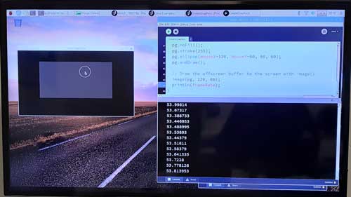
Processing is a library based on Java and have a few functions we can use. For visualizing the performance how the sketch is run, we added this line at the last line of the draw() function:
Here is the reference for the frameRate system variable.
When running the sketch, we saw that the frameRate was not dropping much, about 53 fps. 60 fps is the default configuration.
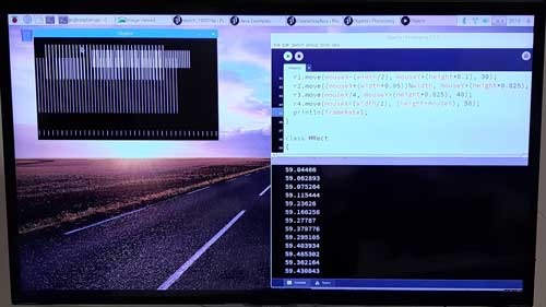
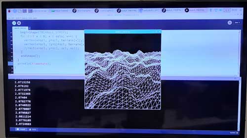
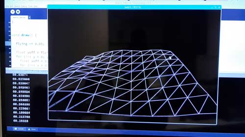
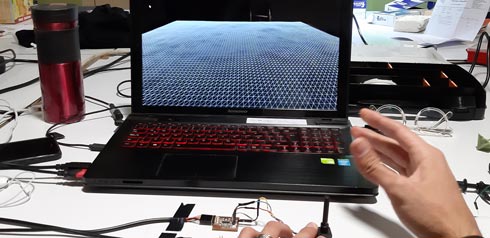
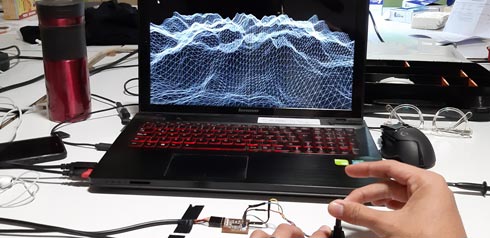
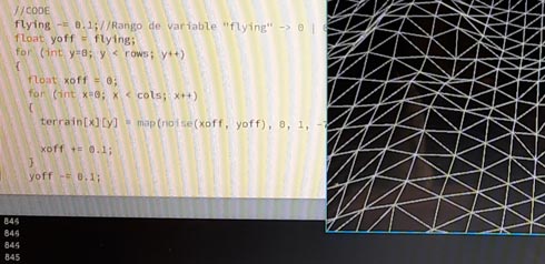
To apply more stress on the Raspberry and try to drop the frameRates, we resorted to Daniel Shiffman's Coding train tutorials. There we found this video and this code to generate a random terrain using the renderer P3D. After running this example, the frame rate dropped to 2 fps, meaning that it was difficult for the Rasberry to run this sketch fluently. By changing a little bit the code and reducing the number of vertices, we managed to raise the frames back to 60 fps, with the visual difference of the simplicity of the terrain.
The Raspberry Pi 1 don't have a wifi system integrated in it as the Pi 3, so we used a wifi usb dongle, but the Raspberry didn't recognized it. For that reason we didn't downloaded Processing in that Raspberry. Our other solution was to pass the program through usb using some Linux functions, but as the official Processing site specifies, this kind of installation needs an expert user to do so, something that neither of us is.
At the end we didn't managed to compare the performance of both Raspberrys.
Student in charge of documentation in this group assignment: Rodrigo Gamboa
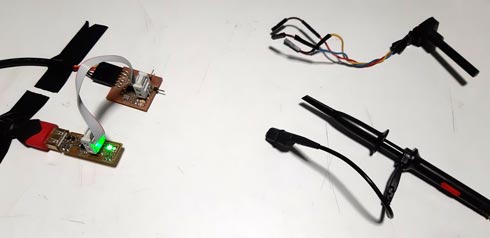
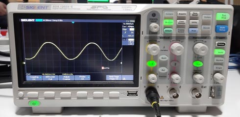
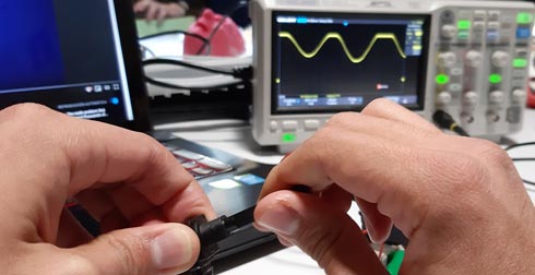
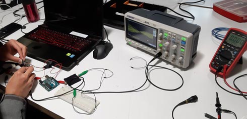
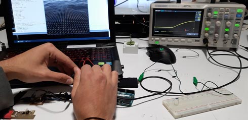
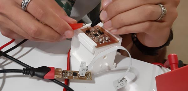
On this week we tested a potentiometer as an input on the previously designed and produced BoredBoard. We tested a code in Processing to have a 3D visual representation of the potentiometer's interaction while checking it on the oscilloscope's interface.
Tool used during this exercise:
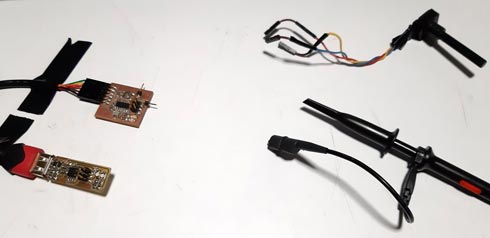
Connections:
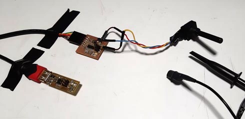
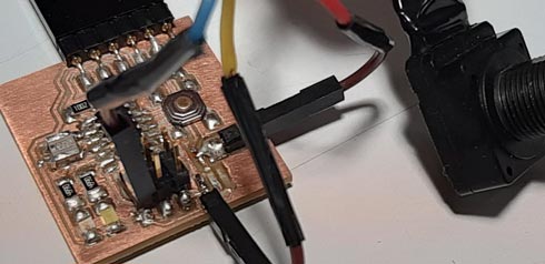
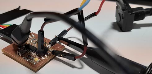
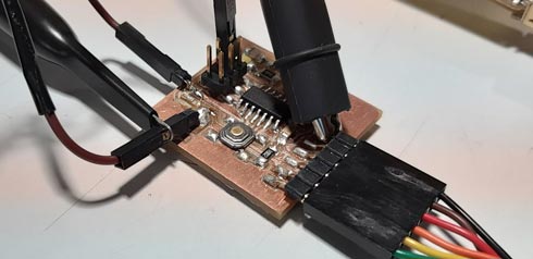
The potentiometer is an input here, and is connected to a ADC (Analog-Digital Converter) of the microcontroller, so we had to map the voltage (0-5 volts) to some values between 0-1023 (10-bit ADC).
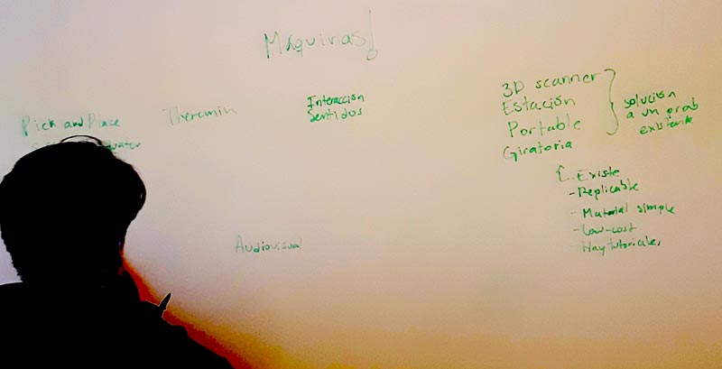
First of all was to search for some ideas about machines made on previous years, or mechanisms intended to use.
After that, it was neccesary to find principles to decide what kind of machine was not possible to design:
Also, it was very important to put together all personal capabilities to agree in the way to work.
After some meetings and research process, and with the help of the instructor, Marta Verde, a Light-Painting machine was declared as the machine to work on.
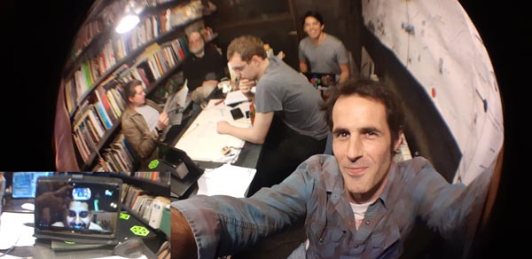

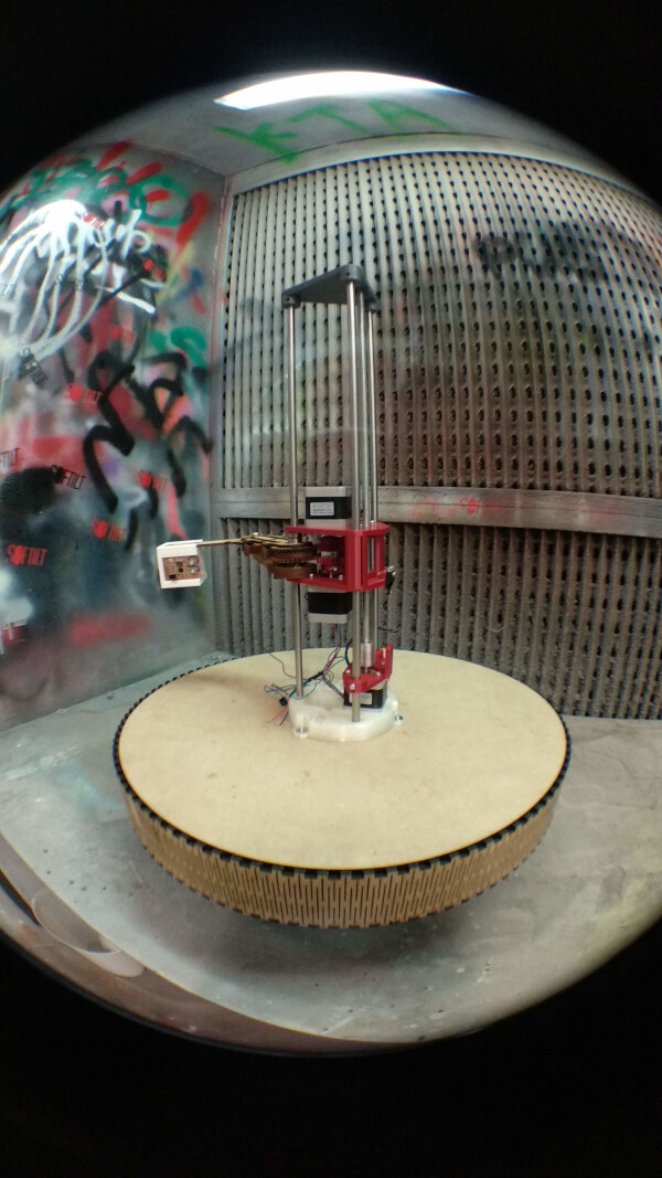
Gianluca’s work inspired the idea of doing 3D light-painted models. For that, a Scara machine will be modified to hold a light instead of an extruder. By taking photos with a high exposure time, with the lights out, the Scara could run a spiral job completing the 3D model made by light.
Here is an example of the different brainstorming processes (and changes) with some ideas of the kind of machine to be made, and of the different behaviours disscused:
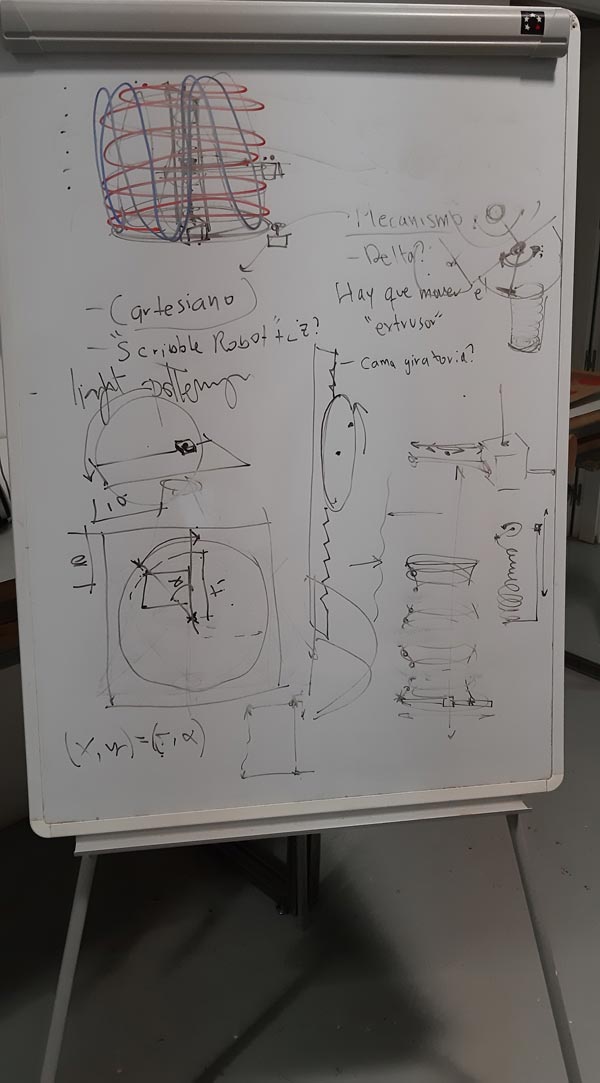
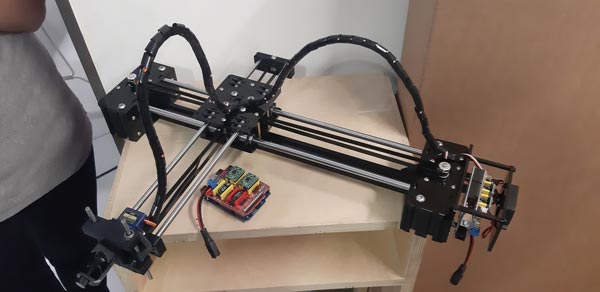
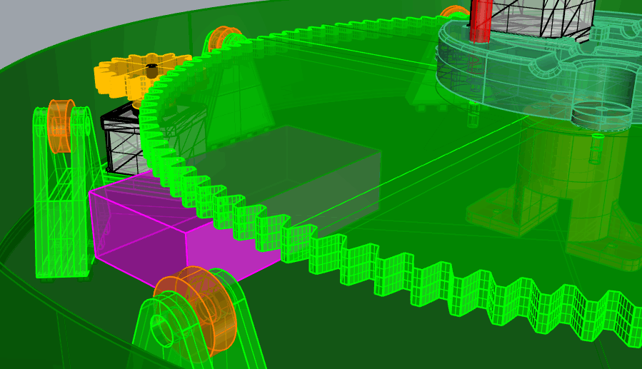
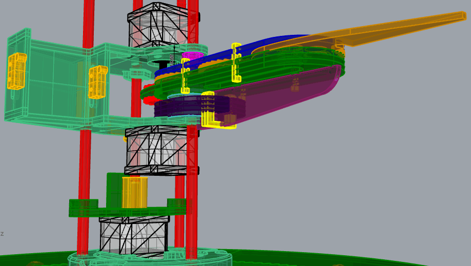
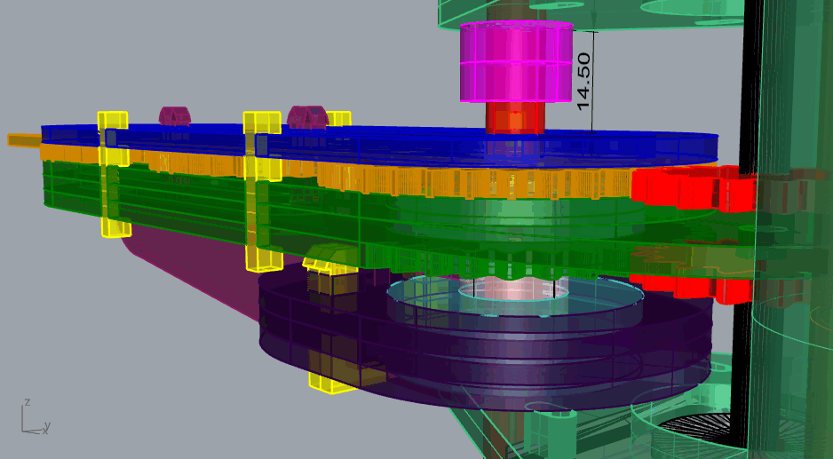
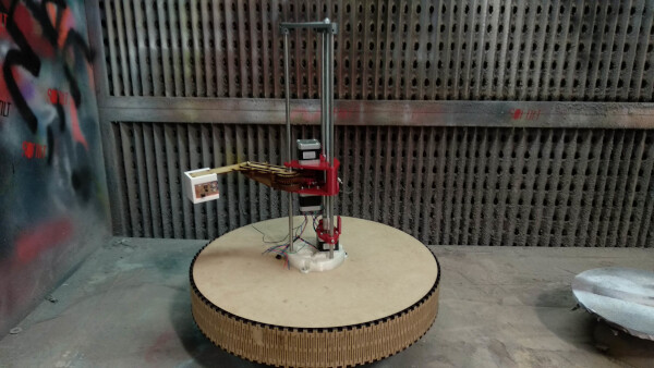
This is the final idea that was decided:
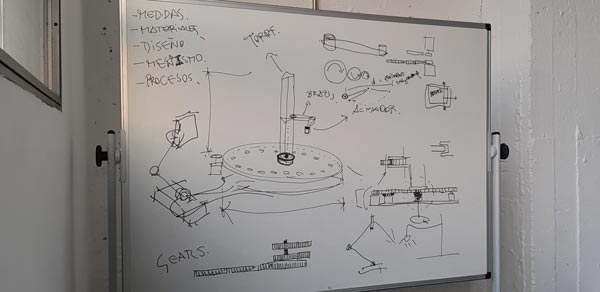
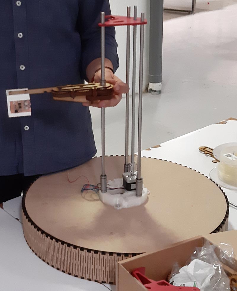
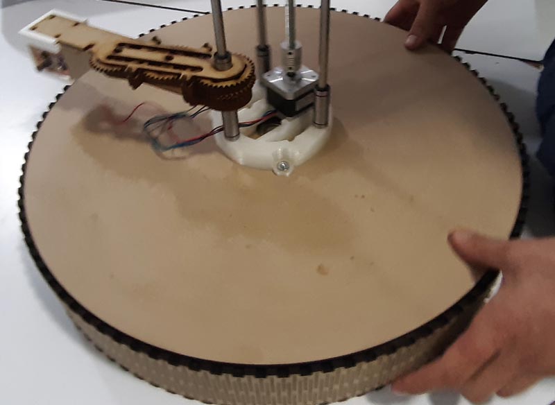
The ligh-painting machine (called Lighscara or Scaralight) has this main parts:
Also, it has this other parts/components:
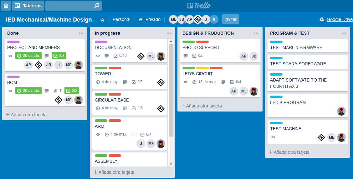
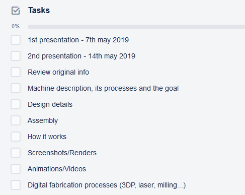
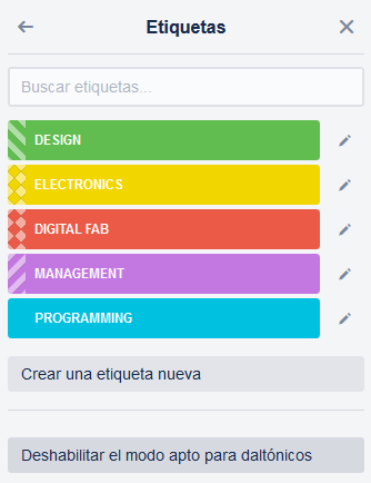
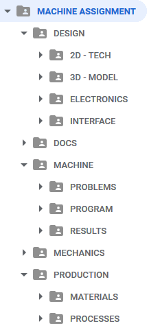
To accomplish this goal, the Trello platform was used to organize the work by defining:
This is the Trello in use, showing tasks, workflow and people in categories:
This is the bom made:
This is the Google Drive platform setup available to share different kind of files along the whole machine project development:
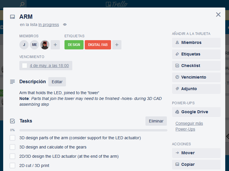
By this way, tasks were assigned to allow working on design before meeting again for the production process.
These are the designs made based on the original one, using Rhino and Grasshopper, Fusion360 and Illustrator.
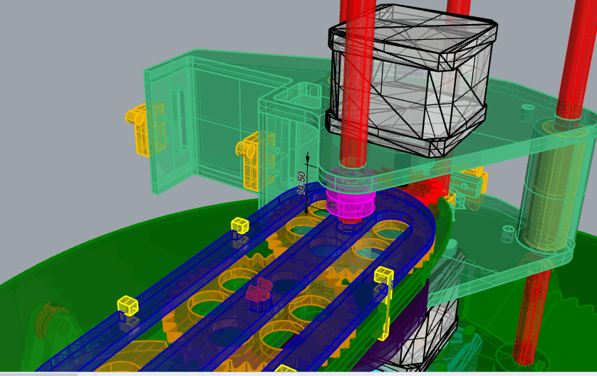
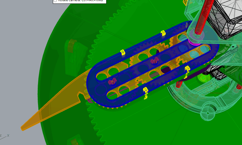
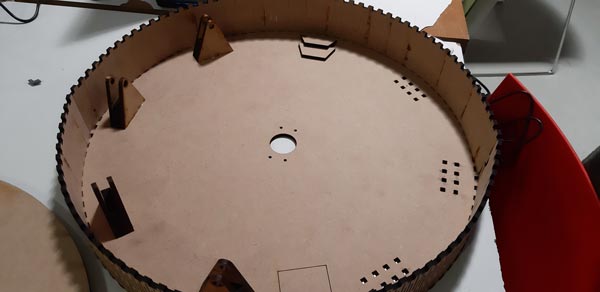
The processes followed to make the machine were 3D printing and lasercut:
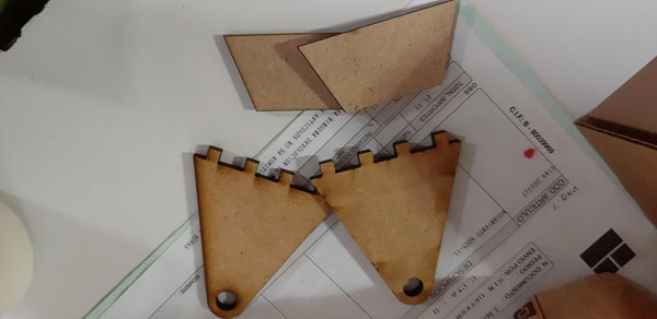
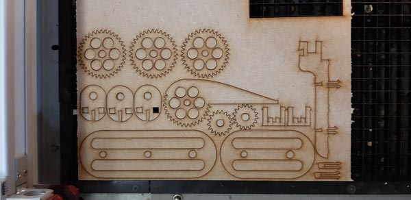
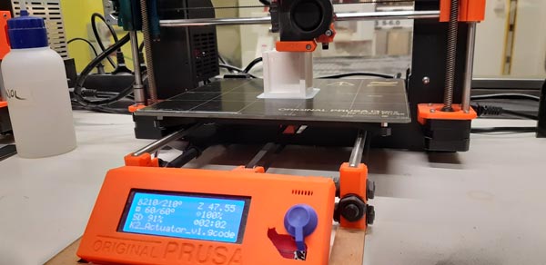
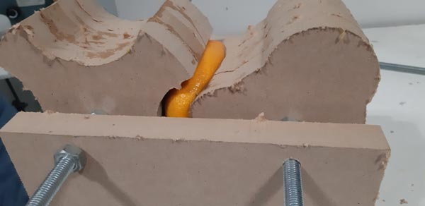
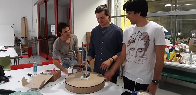
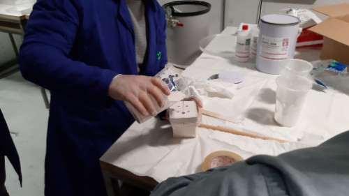
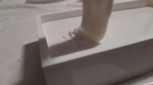
Once the different parts were bought, printed and cut, this was the assembly process:
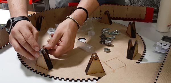
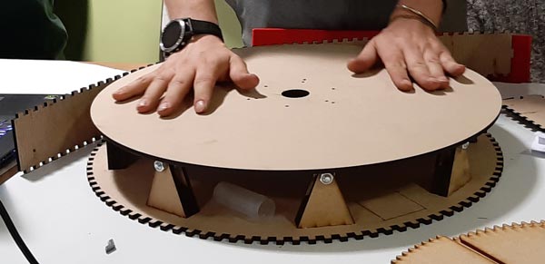
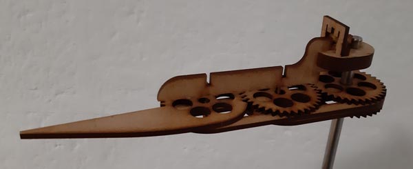

We had to make some changes, but at the and, this was the final result:
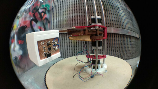
One of the problems founded was that the idea of using a slip ring for connections on a rotatory axis, was out of the bom plan; Adafruit is the only provider with high shipping cost and so much time to deliver the component.
Another problem was that maybe the light would not be seen when the arm passes behing the tower, or if the LED holder hides the LED on some positions. One idea to solve this was to put the LED, extended with wires, at the end of the arm, while the controller board could be placed into the actuator piece near the tower. Another solution for that is to use all the faces of the actuator to hold different LEDs
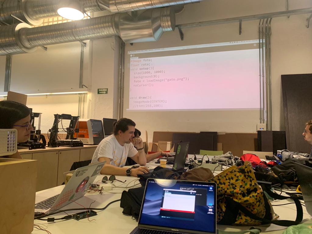
This week we wanted to test as many different software interfaces as possible. As each of us have different projects that needs a specific application, we divide the softwares we where interested in. For example Edu is really into a musical project, so he wanted to explore Pure Data. Pepe, Hugo and Abhay, as Grasshopper users where interested in Firefly. Rodrigo as a new media art enthusiast was interested in p5.js, that is the evolution of Processing for the web. Javi wanted to explore Processing.
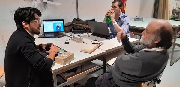
We have the fortune to have a creative coder as our FabAcademy instructor, so Marta made a little Processing workshop to show us the basic commnads and techniques. So everyone of us did experiments with Processing.
The idea with this exercise was to control sound with the sensor board (sonar). The first step was to load to the input board the communication with the interface code. The code used for that had to be mixed with the sonar code.
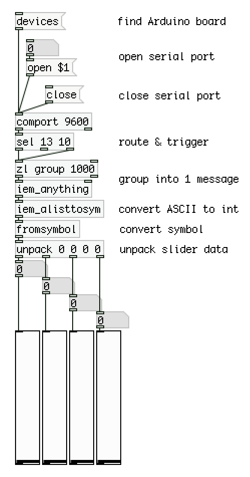
Once the code was loaded on the sensor board, it was the Pure Data interface time. It’s possible to add many different elements to a workspace in where they will be interconnected to send data between them.
It was necessary to stablish a previous communication flow chain before the sound field flow chain. This was the most embarrassing part, because of the different Pure Data software versions. Basically, it’s necessary to join these elements as shown:
More info here.
Depending on the Pure Data version, some .dll or program files were/were not where they must be. This example was made on Pd-extended (discontinued) version because the last Miller S. Puckette’s “vanilla” distribution (v. 0.49-1) was not working when comport element was added to the workspace (although the program files were on the program folder).
The element was not generated fully operative when typing comport at the time to add a new object.
On the other side, the Pd-extended version didn’t have some files on its extra folder… The rare solution was to copy these needed files from the vanilla’s folder to the extended’s one (!!!).
So, ensure to have on %SYSTEM%/%PROGRAMFILES%/pd/extra, at least, these necessary files (not only .pd files, but .dll included):
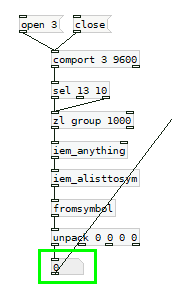
Once the serial communication with sensor was stablished (when clicking open element sensor inputs should be shown on a number box attached to the unpack -the last element of the chain- output):
Finally, it was time to play with sound elements with the input values from the sensor. Here is the whole scheme:
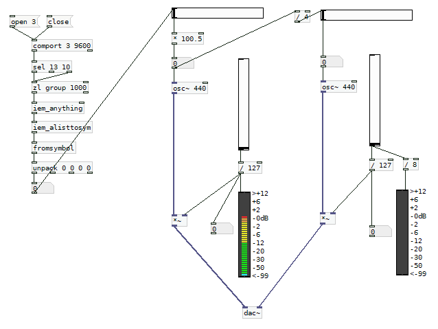
A first generated audio signal is transposed to an equivalent 2 octaves lower new signal. Horizontal sliders control the frequencies and vertical ones control the levels, shown on vumeters.
Here is the sonar sensor working on Pure Data:
See the Arduino and Pure Data files here.