APPLICATIONS AND IMPLICATIONS | WEEK 12
What will it do?
At first my project was going to be something very different to this idea, but it said that best ideas comes from the this that you do. I started to do rock climbing a year ago and it's a sport that I love and it. I though about many ways of create something that could reduce the risk in the mountain or to improve the training in a rock Gym.
I did not found a good idea but, during 3d scanning week and later during molding and casting week I experiment with the face of my trainer to create a personalize climb hold and suddenly I thought that it could be interesting to introduce a sensor in every one of them to recognize the times and movements of the climber. This is maybe too much for a final project and I would like to think more about the best way to do something like that so I would focus in a system to count the time to finish a climb path.
It will be a cheap version of the one that is going to be use in the olympics (this year it will be rock climbing for first time) but focused in start to collect data for regular climbing as part of a bigger system not a timer focus in speed race.
who has done what beforehand?
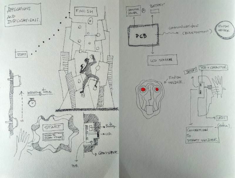
There is a professional system which is based on pressure (you can see at the beginning of the video) but I would like to do something that is inside the climb hold so timer starts when the climber touch it.
This project made in 2016 has many paralelism with mine. There is a screen and a capacitor sensor that it would be in mine too. On the other hand I will use 2 capacitor sensor situated in a difference distance one to start the timer and another to stop it.
What materials and components will be required?
For the additive and subtractive process it will be necessary:
- 3d print PLA for the piece
- Silicone for the mold
- Polyuretane resin for the final rock climb hold
- Acrylate can be use for the screen display, but I would probably integrate in the first climb holder
For the electronics it will be necessary:
- 2 pcb connected.
- 2 capacitor sensor that I can made by myselft.
- 2 attiny 44
- 1 LCD SCREEN
- 1 battery system
- 8 Red LEDS
- 1 bluetooth sensor (i will explore this during the communications week)
- resistors and capacitors (I need to design the circuit before know the quantity)
Where will they come from?
All the part can be found or fabricate in the Fab Lab. At this point I'm only worried about the bluetooth system and the batteries.
What parts and systems will be made?
Everything will be made except the electronic components.
What processes will be used?
I will use the following processes
- 3D DESIGN for the form of the climb holders
- 3D PRINTING for to create base for the mold
- MOLDING AND CASTING for the final climb holder made with poliuretane resin.
- ELECTRONICS DESIGN AND PRODUCTION for the different PCBs
- MICROCONTROLLER PROGRAMMING
What tasks need to be completed?
I will use the following processes
- 3D DESIGN for the form of the climb holders
- 3D PRINTING for to create base for the mold
- MOLDING AND CASTING for the final climb holder made with poliuretane resin.
- ELECTRONICS DESIGN AND PRODUCTION for the different PCBs
- MICROCONTROLLER PROGRAMMING
What is the schedule?
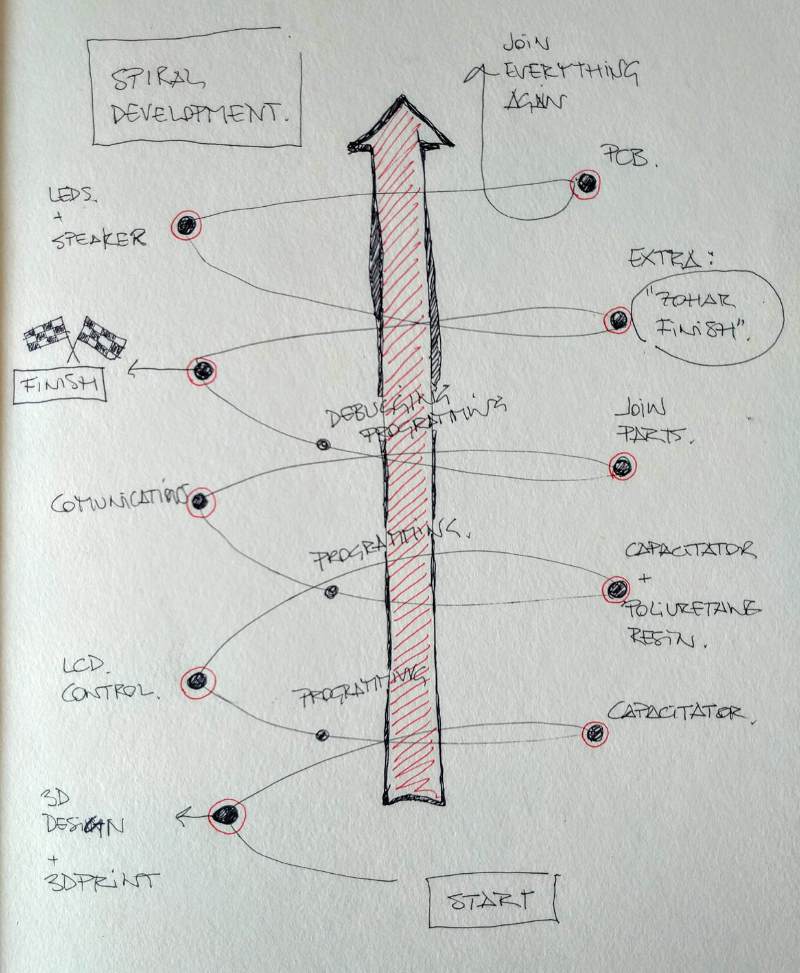
Well, I have to close this part but this can be a first darft
- 1. 3d design and electronics design with fusion to prepare the size for holes.
- 2. Capacitator test and fabrication.
- 3. If capacitatr works correctly then 3d printing and molding and casting (it's the longest process of all)
- 4. Electronics production and solding
- 5. Programming and debbuging
- 6. Joinning parts.
- 7. Testing and debbuging
- 8. FINISH!
If everything is finished before the day D it is possible to make some extra improvements
- 1. electronics design production for LED and SPEAKER
- 2. Programming
- 3. Testing and debugging
- 4. Installationn
- 5. Finish 2
Extra Extra assignment that I won't do: Connect the system to a cellular app.
- 2. Programming
- 3. Testing and debugging
- 4. Installationn
- 5. Finish 3
What other questions need to be answered?
Is it work? How sensible the capacitator sensor can be? would the poliuretane resin curate affects to the final result? Is it possible to use a bluetooth connection? How much the battery last? Do I need to use wires or think about a small solar panel? How could be improve? Could be connected to a mobile phone and recognize each path?
How will it be evaluated?
My idea is to install the system in my rock climb gym so my friends and other climbers could test it and give me new information to improve the result and see how useful can finally be. Maybe the electronics and the programming are not so ambitious but I don't have any background with this and for me it going to be a real challenge. I hope it will be my first step to a bigger and more complex system related with training for climbing training.
The week of machine design I changed my idea for the final project one more time and I had to think again about the Applications and implications of my final project. Which you can see now (16 of June of 2019) here.
HELIOTROPO. Final project Applications and implications
What will it do?
Heliotropo is a kinetic structure tha transforms ambient light into movement an reflect. The Object has been designed to interact with another machines transforming the signals read by the sensors into a peaceful movement that becomes more agressive in the darkness. As the light goes out the machine starts to move faster and producing different effects with light.
For the future i would like to implement more motors and movements that will make the piece more complex and accurate too the real proporties of light as we percibe right now. For the moment I only used a phototransistor as light input device. I bought a
Who's done what beforehand?
There are many references that I can think about, specially for the movement but I can the most direct and important ones are:
For movement
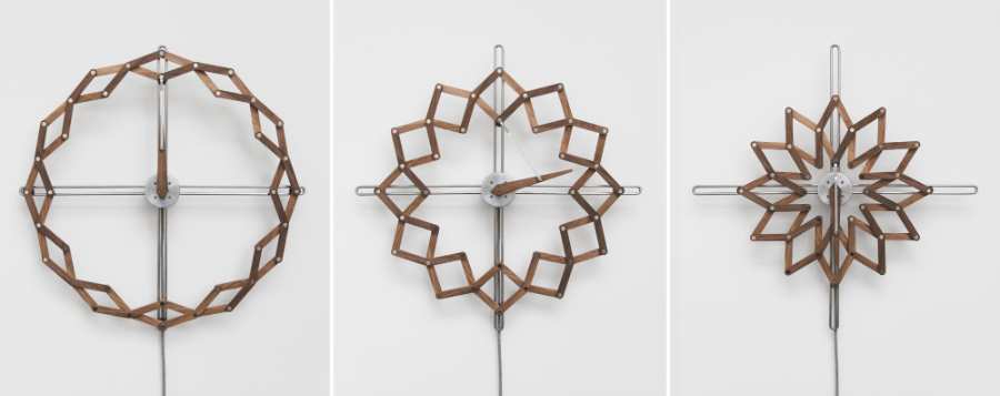
- solstice, by Matt Gilbert,
a kinetic clock, that rotares with similar structure to the one I have used
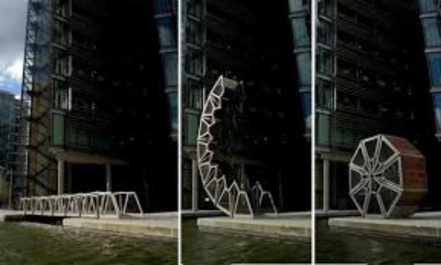
- Rolling bridge, by heatherwick studio.
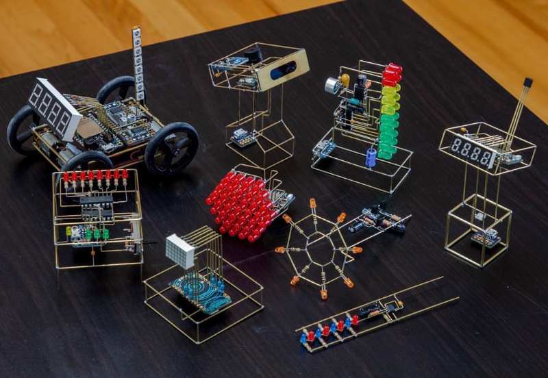
For electronics
I like the idea of free form circuits were board and wire are replaced by rods that connects different elements creating a 3D shape. This way of creating circuit has two advantages for me, firstly it makes possible to hide wires without in plain view. Secondly you have less elements because structure components and electronic connections are the same and thirdly it creates a beautiful mix of elements.
In fabacademy it's mandatory to design and create a board by milling it so I can't use this method for all my circuit (it would be a crazy idea for the final project, anyway) But I want to use it somehow, maybe to connects two boards or to join elements that are far away from each other.
- Mohit Boite circuits.
The idea of using structure and rods to create a beautiful circuit without using wires.
- New Babylon, Constant
An artistic proyect were electronical components are used to create structures.
.jpg)
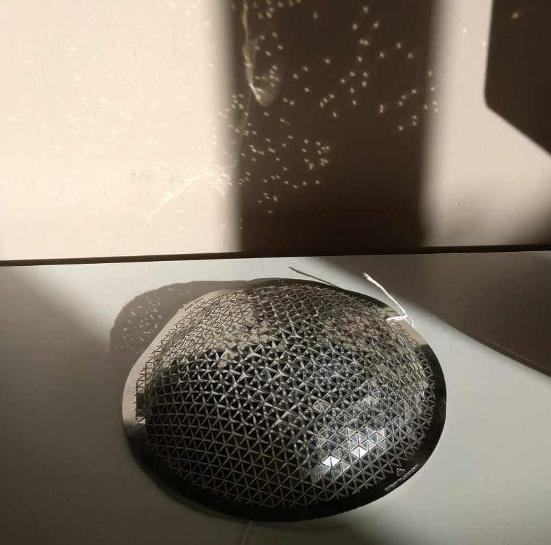
- Push, by Fundamental Berlin
A lasar cutted piece of stainless steel that can be deformed, as an extra the deformation reflex light in many different directions
What will you design?
I think that I would design most of the system, starting by the structure and the mechanism and finishing with the board. I don't plan to buy anything finished so this is going to be a huge part of my job for the final project.
If I buy something It will be those elements that exist for the industrial manufacturing, such as screws and connections for wiring. I like the idea of use them for a different purpose that the one for what they have been made.
What materials and components will be used?
The base structure and the mechanism is made with acrylic 4-5mm (depends on the part), for the vertical structure I used copper rods, all is connected with binding screws. The mirror are made with a PVC mirror (metalon) that can be deformed using heat and Which I cutted with the vynil machine. The rest of the parts (connections between different materials or the stepper to the structure) are 3d printed.
Where will they come from?
I've bought the copper rods and the Metalon, which was very specific, the rest of the elements can be found at the lab. I will look for them on internet and in specialized hardware stores around Madrid that I know very well from other times and projects.
How much will it cost?
The total cost was around 110€, but it's that I had to spend more money in the previous prototypes also there are some parts that can't be buy individually. Here is the complete BOM
Donwload from hereWhat parts and systems will be made?
I thinlk that I will made all of the elements, I really want to be my final project to be particular and special in every way and component. Also, there is nothing so complex to justify in front of my evaluators that I bought it.
What processes will be used?
- Vynil cutting For the origami pattern mirrors
- MillingFor the electronical boards
- laser cutting For the main structure and the mechanism.
- 3D print For the connectors and the rest of the special parts.
What questions need to be answered
- Is it possible to use copper rods to communicate different boards? would they be my rods too thick for this purpose?
- Will it move? will it move fluently? will it move at all?
- The RGB light sensor. Will it works? Will it read the colors correctly?
- The neopixels, will be enough? how much light do I need to be reflected in the mirrors? or what kind of mirror do I need?
What questions were answered?(updated after presentation)
Many. Enough for me to want to improve the object, upgrade some solutions and try some alternatives.
- Copper rods can be used to transmit electricity and also electronic signals.
- The mechanism are tricky, I really expend a long try trying to understand what would move if I do something, tolerance are also important.
- About electronical boards, double face circuits works fine and gives the chance to create very small boards without using jumpers.
- This is not answer but is something I want to think about. But in theory
- Neo pixel are a good solution to save some Pins but they are expensive and although I can get some reflects my pins are not enough
How will it be evaluated?
I hope better results in the mechanics than in the electronics, but I hope to do a nice job in both of them. I would like to value the aesthetics and the details. I don't want to do something that works, I want to do something that works well and it's well finished. Not a "chapuza" a spanish way to say that you solve it but without taking care of details to do a good job.