Assignment 14 Communication
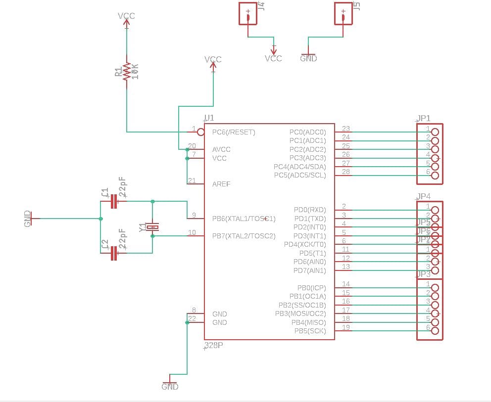
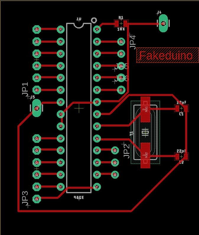
The Arduiono-Clone communicates
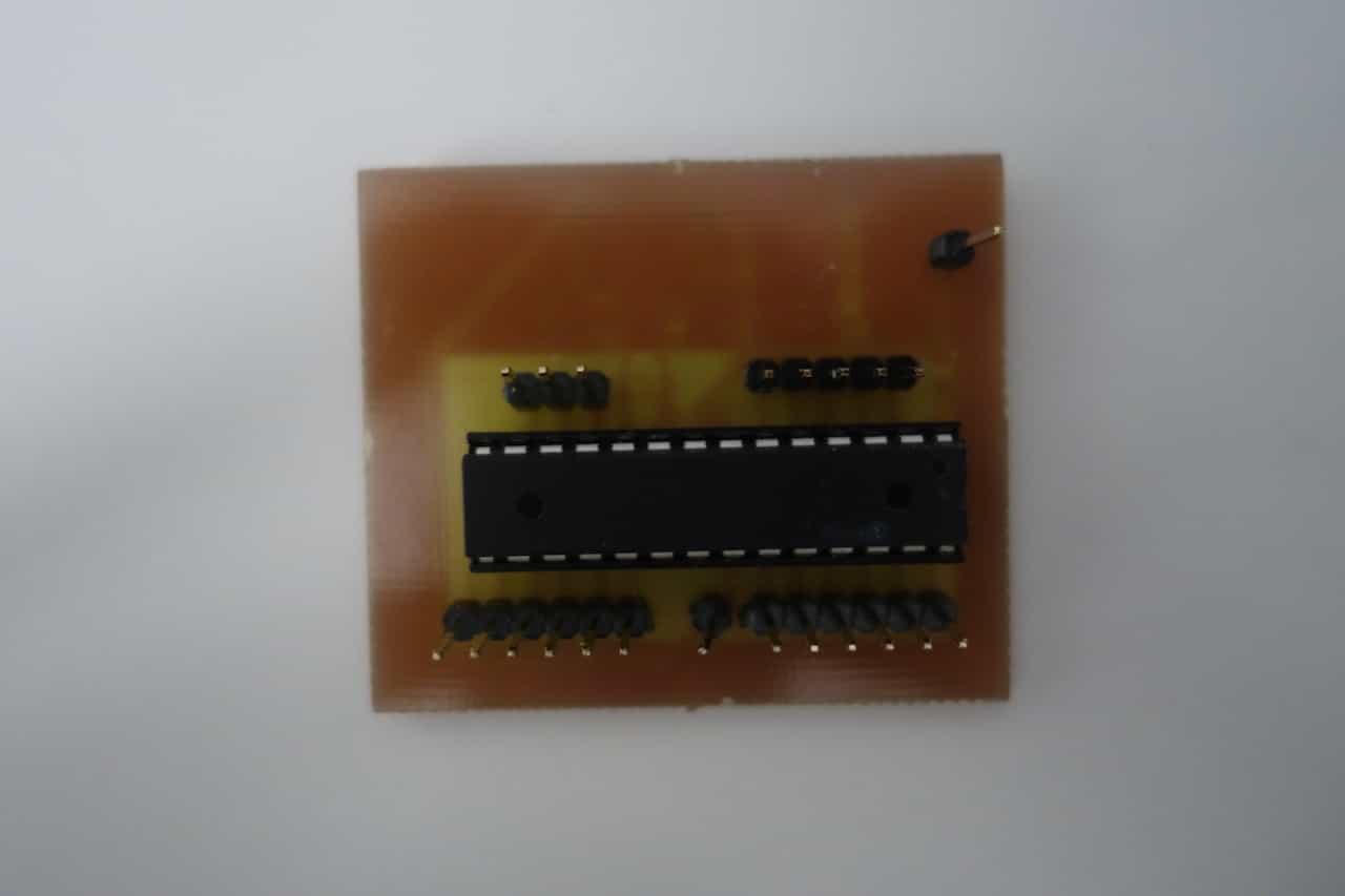
Cloning an Arduino
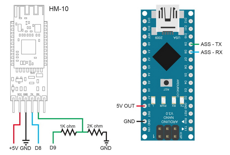
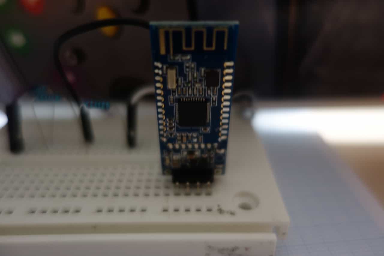
Bluetooth communication
BLE uses a number of predefined services a full list can be found here. But in the following I only use custom services.
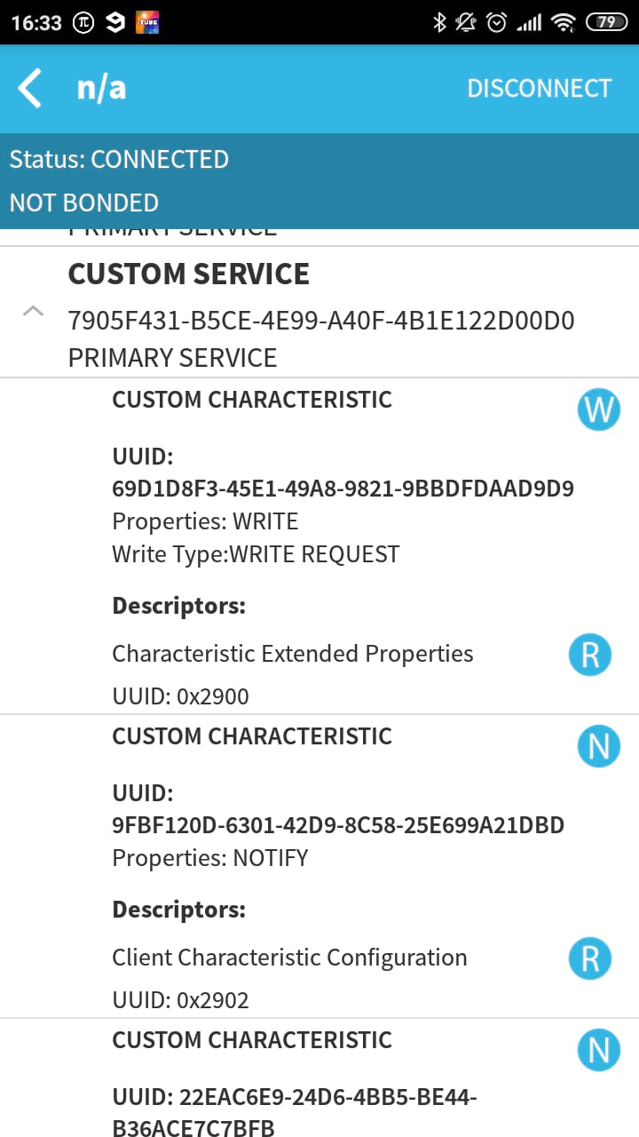
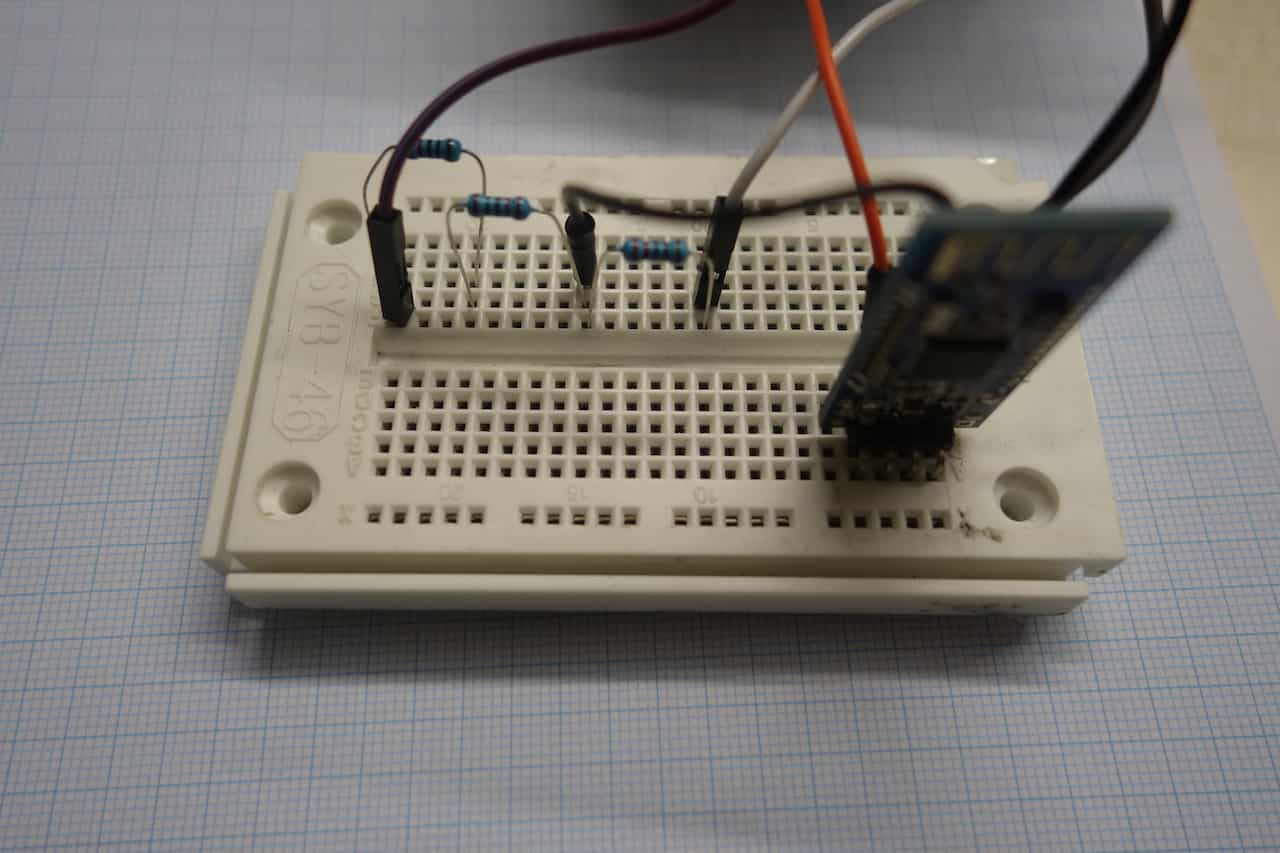
Look in the video at bottom to see how it works live. For troubleshooting and more about how to work with the HM-10 refer to this tutorial.
Here "A" and "B" a single bytes of Data (One Letter or number) and "payload" can consist of multiple bytes.
The controller reads the serial input of the bluetooth-module till a "[" is received then every byte including the "[" is saved until a "]" is received after that the message is processed. If an other "[" everything previously saved will be overridden because the first message was not transmitted correctly since is has no "]".
The first step of the message processing is a sort of integrity check here the format of the message is checked. Right number of colons right position of colons (see Template above). Then the message is split up into the "A","B" and "payload" parts, this will be relevant in my final project to address groups of leds.
Example: [1:2:512]->Leds in subgroup 2 of group 1 change color to 512
For now the code [0:0:1] sets on an Led and the code [0:0:0] turns it of when sent to the microcontroller.
This protocol is ver help full when dealing with multiple in and outputs because you can simply group and subgroup (first two entries) them
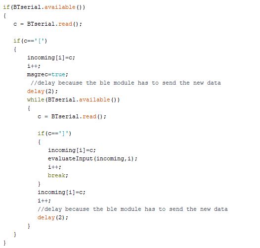
When the BLE module receives a message BTserial.available() is true now the message can be read bit by bit via the command BTserial.read(). In this case the programm waits for an "[" in stream and the writes the following message into the buffer incoming using the variable c.
To send stuff from the microcontroller simply use the command BTserial.write("some message").
Other Protocols
I2C
With the Serial clock pin (SCL) and the Serial Data pin(SDA) the Attiny45 can use the I2C protocol. To communicate on of the processors has to be the master and the others the slaves. (one master can have multiple s laves but not the other way around). Each slave has an 7-bit address. The master has no address and generates the clock signal for all slave so everything is synced.WS28/12
The WS28/ Led stripes use a one way communication method where in each message has a predefined length and each receiver takes a part of the message. SO the first 3 bits are for receiver 1 the secon 3 bits for receiver two and so on. more can be found in my Output-AssignmentFavourite beverage of the Assignment

Just black tea to stay awake and maybe to hunt some Wyvern
