Assignment 12 Output Devices
In this weeks Assignment we had to make a board to output something.
I decided to test WS28/12 Leds since I want to use them in my final project.
I decided to test WS28/12 Leds since I want to use them in my final project.
Tools used
- 1x ATMega 328P-PU
- 1x 16Mhz Quartz
- 2x 22pF Capacitor
- 1x 2x3 SMD Pinheader
- 1x 10kΩ Resistor
- 3x 1x1 Pinheader
- 1x Arduino Uno
- Jumper Wires
Making the board
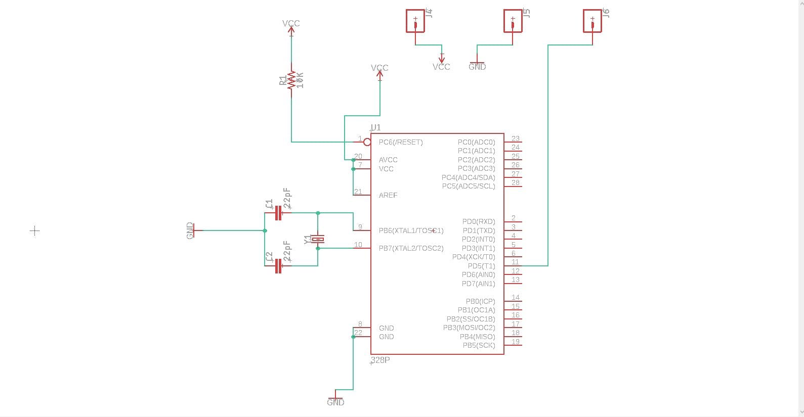
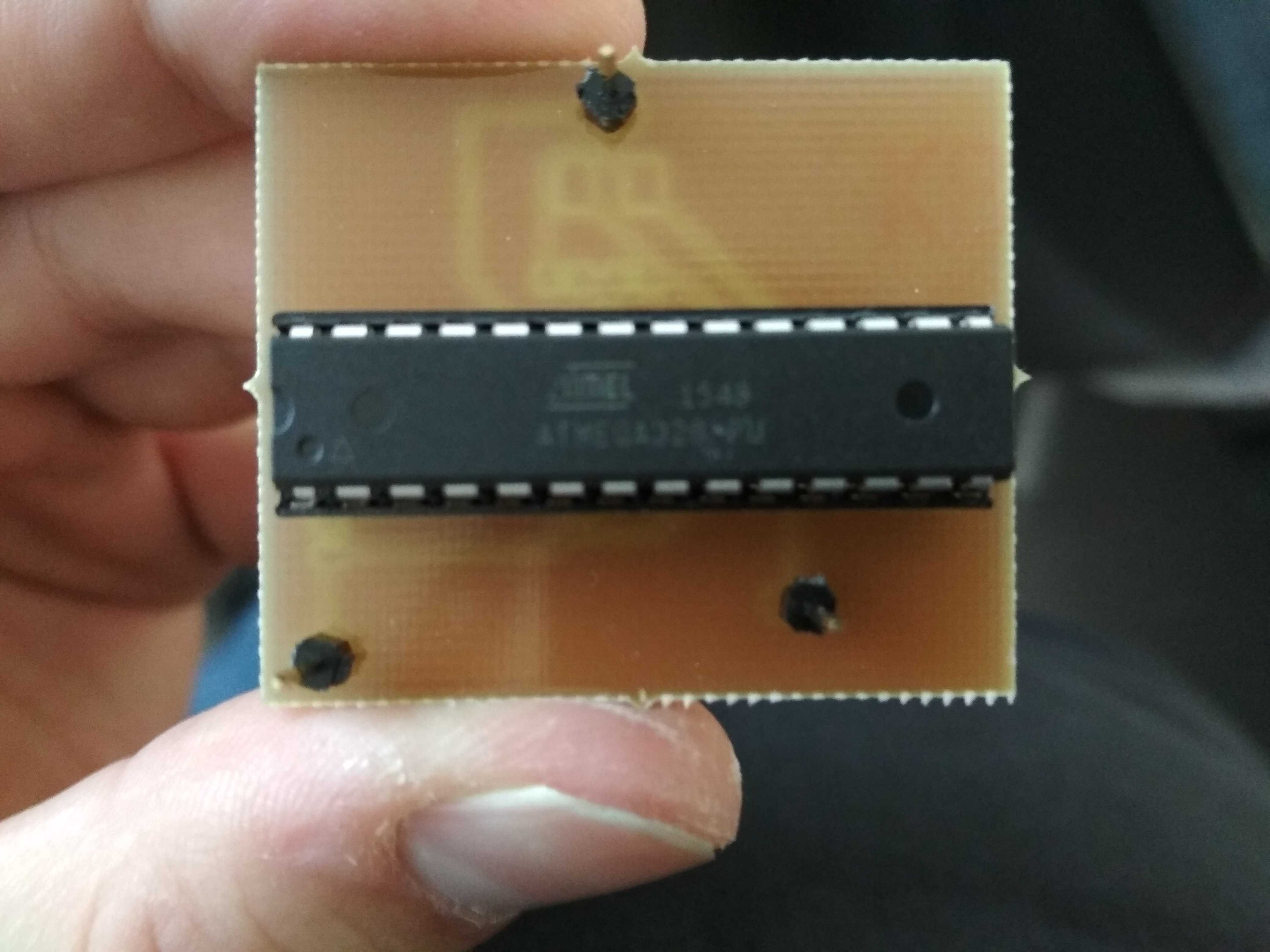
Since i want to use the ATMega 328P-PU I need to design a special board for that the ATMega needs a 16 Mhz quartz and a pullup
resistor at its reset pin. Further I decided to program the chip externally so I had to make it removable. To
accomplish this I just used a pinheader.
This makeshift arduino is just a proof of concept for the upcoming assignments, for now only one pin is accessible. But I can easily be modified so every pin is accessible.
This makeshift arduino is just a proof of concept for the upcoming assignments, for now only one pin is accessible. But I can easily be modified so every pin is accessible.
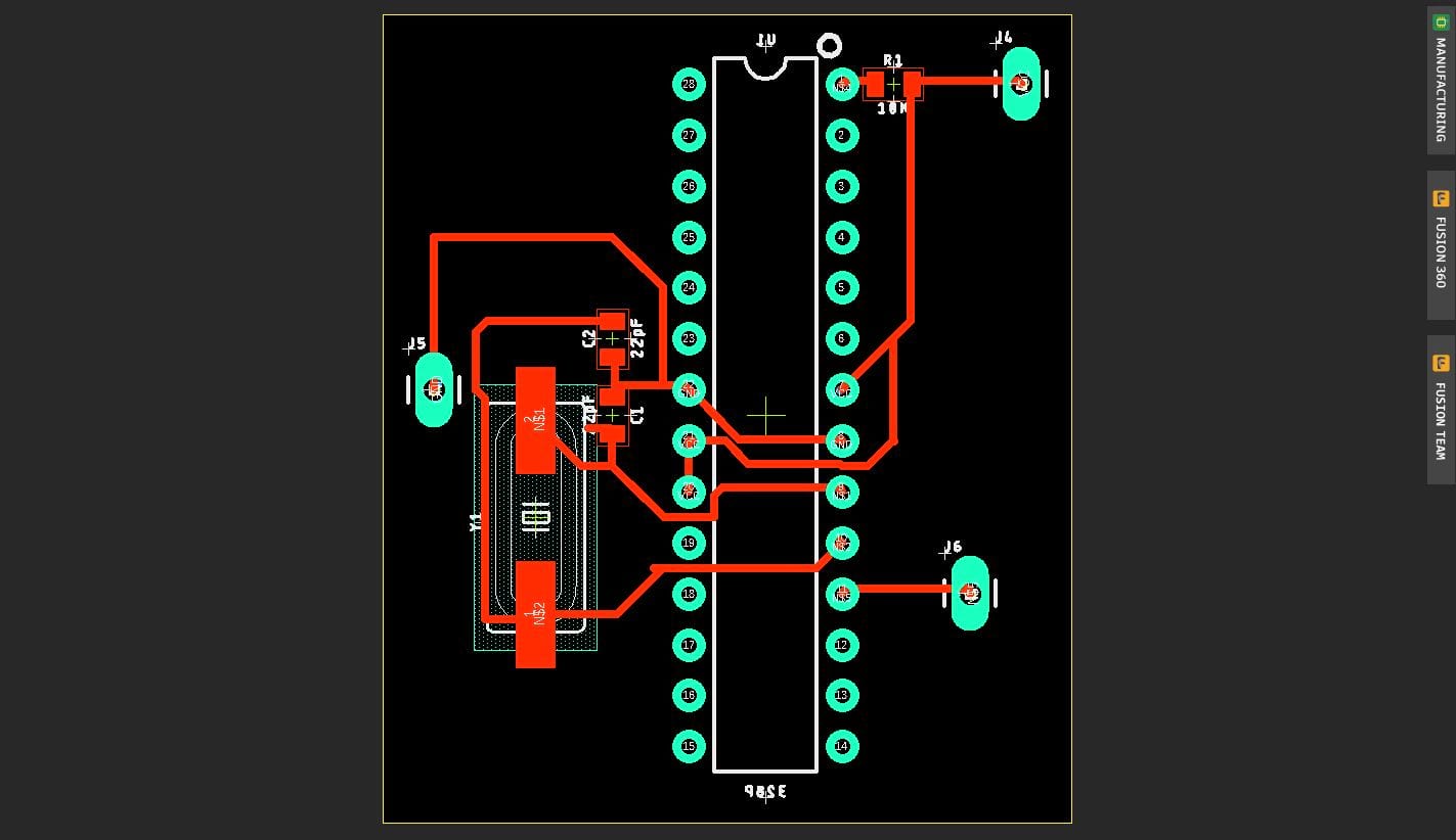
The footprint I used for the chip was unfortunately not correctly rotated since I used just the toplayer and
my pinheader was a throughhole component. To resolve this problem i just mirrored the footprint while designing a board.
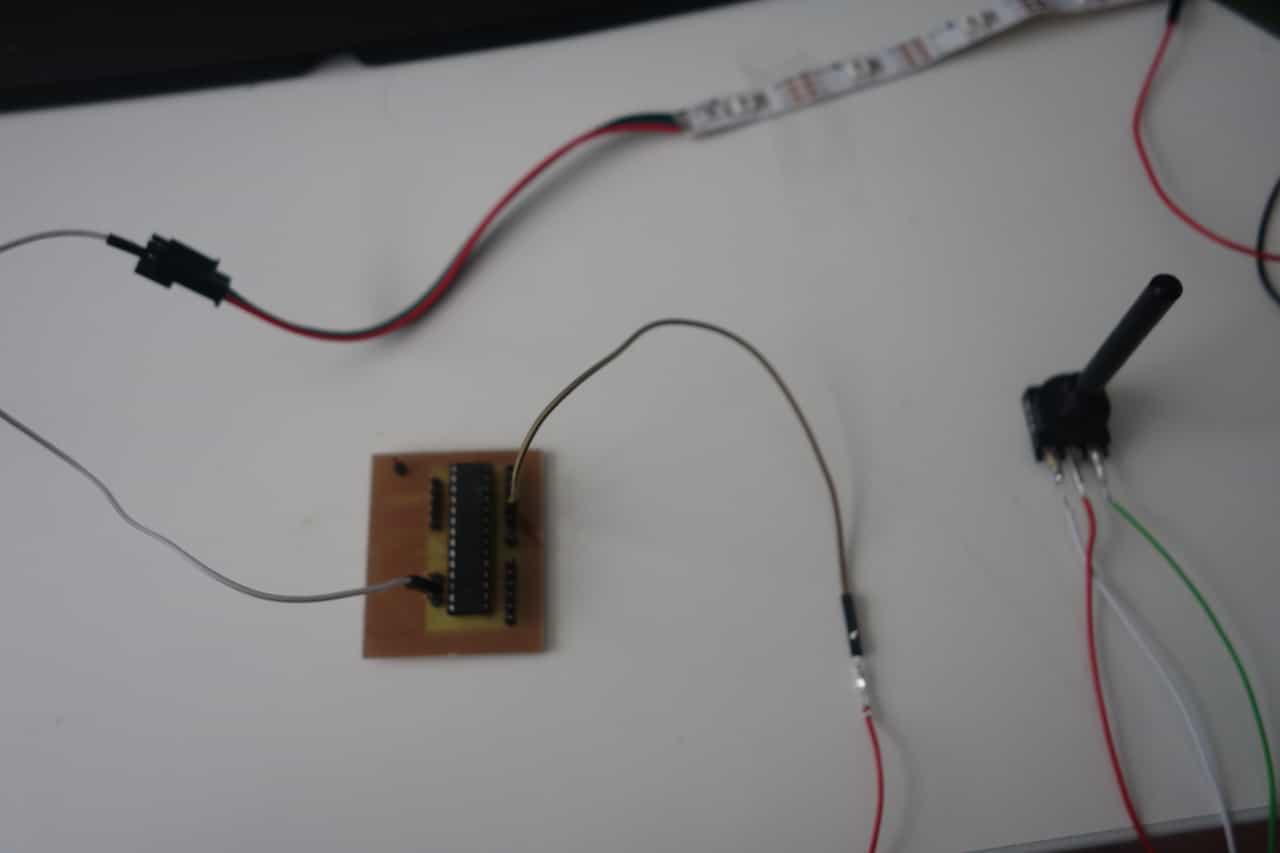
The pin on the left is the GND pin the upper pin on the right is the VCC pin and the lower one is the data pin (Digital 5). Im using the Arduino on the picture to power the board (because I had no other powersource at that moment)
The pin on the left is the GND pin the upper pin on the right is the VCC pin and the lower one is the data pin (Digital 5). Im using the Arduino on the picture to power the board (because I had no other powersource at that moment)
Programming the Board
In reality a WS2812 LED consists out of 3 separate LEDs: a blue one, a green one and a red one.
Each of them can be modified individually.
Basically a LEDstripe works like this: you send data for each led one after an other: Blue(led1),Green(led1),Red(led1),Blue(led2)... and so on.
More detail: Every Led need 24 bits (8bits per color) of data the rest ist forwarded to their neighbor.
Since the are 8 bits of Data there are 256 (0-255) possible levels of brightness for each color. To send data for example an 9 (0000 01001) one bit is sent for every circle of the clock beginning in the front. Since it is a digital signal High is sent for a 1 and Low for 0.
You have to keep track of the states of all LEDs in your stripe, because you have to send the whole data again when one LED is
Since my Final project contains many LED and multiple stripes I decided to use an Library which I used for different other projects too. This will make it easier to narrow down mistakes while using a a large amount of stripes.
When using a small amount of LEDs the power supply of my board will be sufficient but when using more LEDs you may need an additional power source.
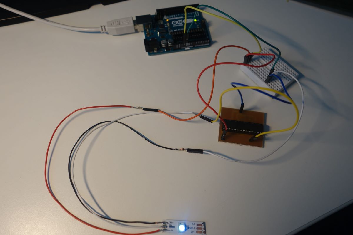
This is the setup with the Arduino as power source.
Making Colors Linear
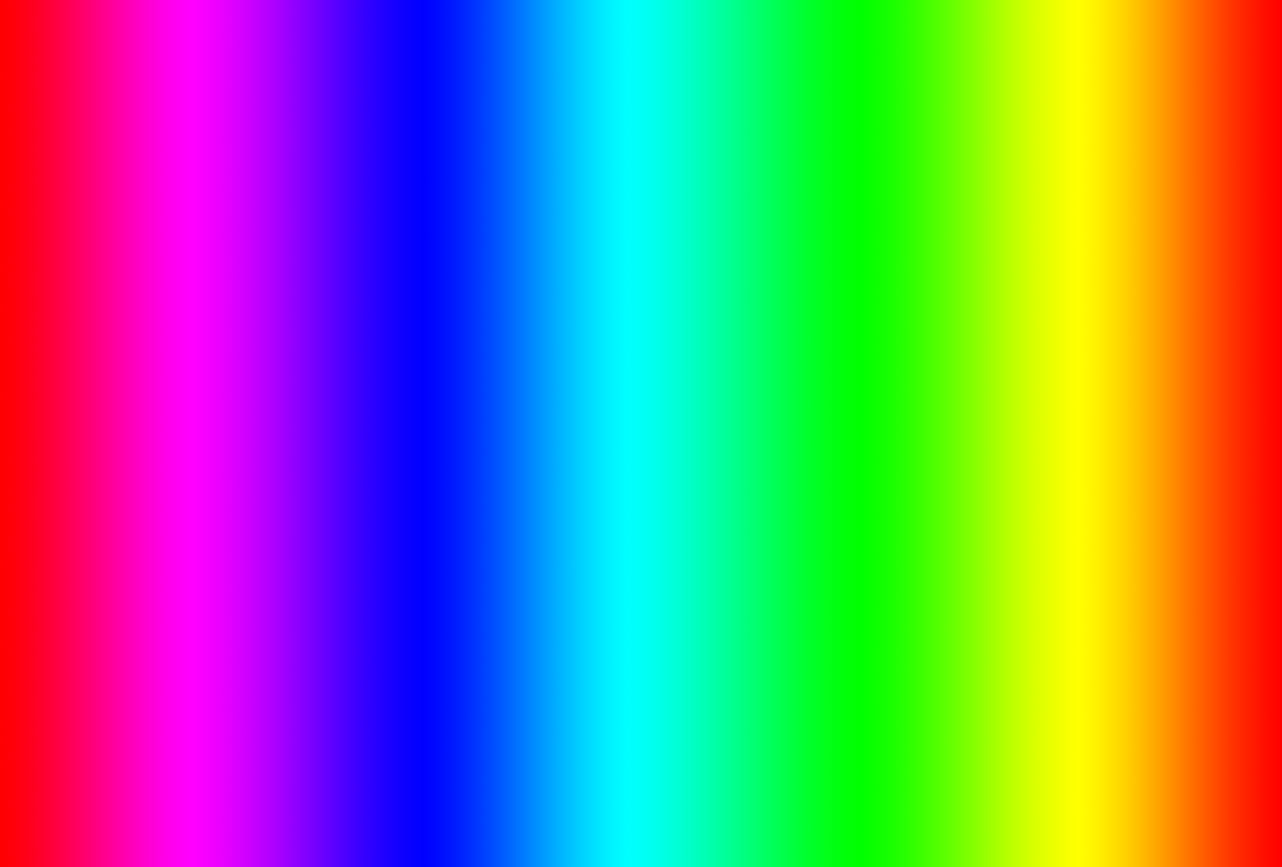
I wanted to make a color circle like this with a linear.
As you can see the color drifts from red to blue to green and back to red. To get this gradient we begin with (255,0,0)(red,green,blue). Then we start adding blue and removing red step by step. Till we reach (0,0,255). Now do the same for blue and green and then for green and red.
As you can see the color drifts from red to blue to green and back to red. To get this gradient we begin with (255,0,0)(red,green,blue). Then we start adding blue and removing red step by step. Till we reach (0,0,255). Now do the same for blue and green and then for green and red.
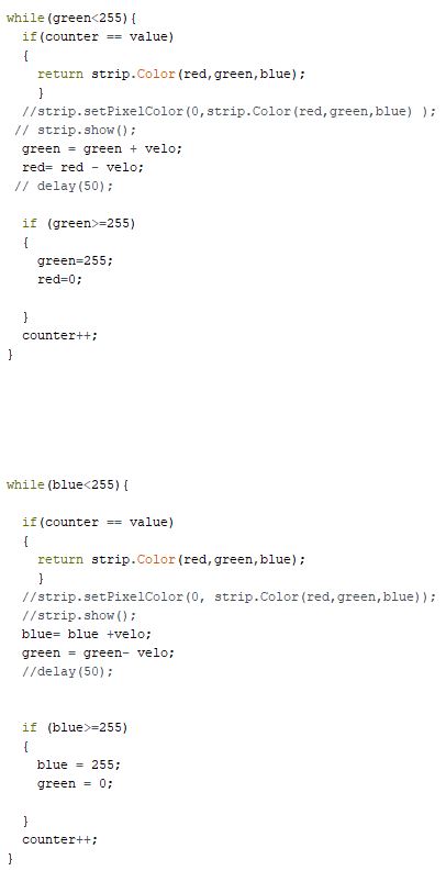
Now with the theory in mind we can program a function that maps the numbers from 0 to 765 to a uint32_t
which represents a color which can be sent to the Led strip.
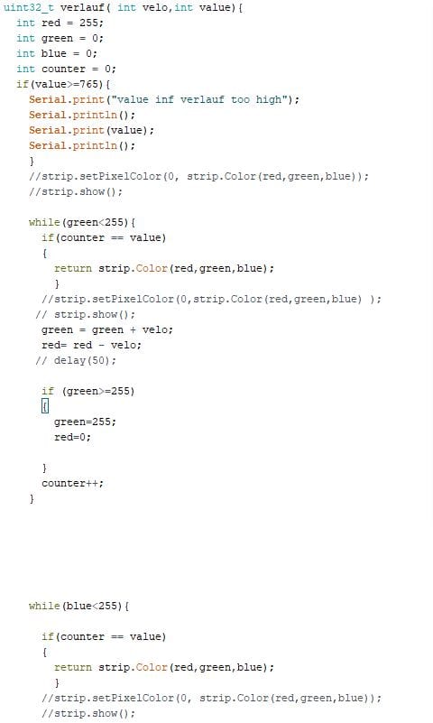
In this codesnippet you can see the transitions from red to green and from green to blue (while reading it again: it seems like I programmed it in the opposite direction as described above). The velo variable was an old method to control stepsize which proved to be to inefficient. This value should be left at one and the stepsize should be controlled outside of this function via the counter variable. The code that is commented out was debug code to see if the function works correctly. I had a nasty bug where I returned the wrong value or another one with strange over and underflow (curse you velo variable).
In this codesnippet you can see the transitions from red to green and from green to blue (while reading it again: it seems like I programmed it in the opposite direction as described above). The velo variable was an old method to control stepsize which proved to be to inefficient. This value should be left at one and the stepsize should be controlled outside of this function via the counter variable. The code that is commented out was debug code to see if the function works correctly. I had a nasty bug where I returned the wrong value or another one with strange over and underflow (curse you velo variable).
Play a little Game
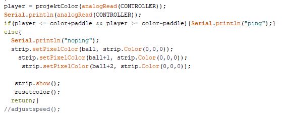
Now with the color function we can build a 1D-Pong Game. So when you rotate A knob the color of your
paddle changes. When the paddle has the same color as the ball (just a moving pixel on the stripe) the ball
will bounce back. I did not program an opponent or 2 player mode you simply play against a wall which always
shoots the ball back at you. On the left you can see a code snipped of the game-code which contains the
collision-detection. For more detailed information how the game works look into the code itself it got a
bit long and it would be to complicated to discuss everything in detail. Basically it works like this the ball
moves from the end of the strip towards the payer in every step the color changes a little (following the gradient),
when the ball hits the paddle the program calculates if the ball is when it is hit the ball moves back to the
end of the strip and then again towards the player. If its not hit the whole program simply starts from the beginning.
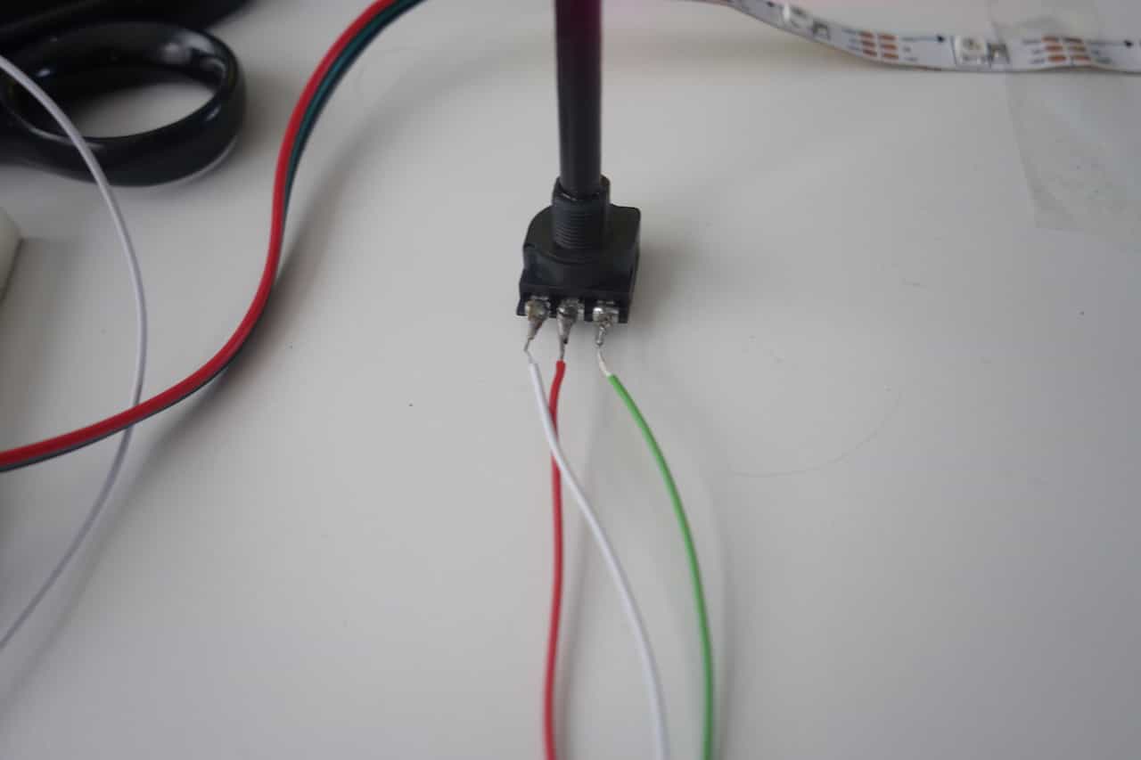
First we need a controller I simply used this potentiometer (Left goes to vcc middle to A2 and Right to gnd).
I also used the controller I made for the bluetooth assignment. The Instructions can be found here.
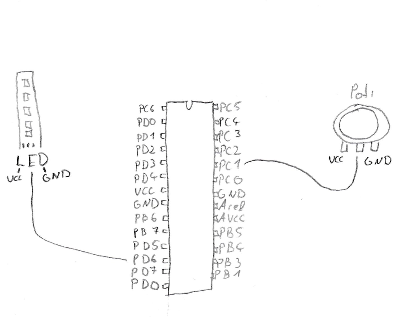
You should wire it like this. Keep in mind in this picture are the power lines not connected
(connect the gnd and vcc pin of the board, the strip and the poti to you power source which is not in the picture)
Favourite beverage of the Assignment

Just black tea to stay awake and maybe to hunt some Wyvern