Output Devices
Week 13 · [ 11.04.2018 - ]
- Add an output device to a microcontroller board you've designed and program it to do something. (Individual Project)
- Measure the power consumption of an output device. (Group Project)
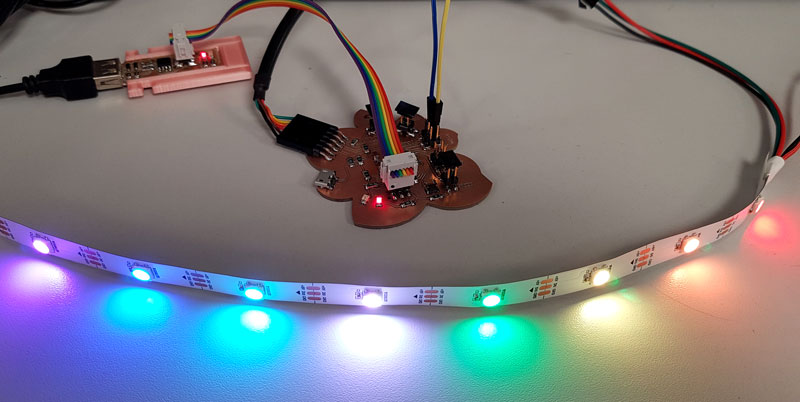
This week I tested NeoPixels strip as my output device. I will use NeoPixels in my final project so familiarizing myself with them was very interesting and important step towards the development of my project. During the week I learned to understand better the current consumption of the NeoPixels (which is a lot if all of the LEDs in the strip would be ON at the same time), and got an idea how to programm the LEDs for my final project.
Deciding the Output Device: NeoPixels
Last week I fabricated the main board to use also in this week's assignment. In the end of the previous week / for beginning of this week I made a few modifications for the board but then I was ready to learn Neopixels very quickly. The Trace- and Outline -files, as well as .rml -files are included in the Week 12 files.
For a start, I learned what are the alternative strips that there are available, what is the amount of LEDs I will need, and what is the voltage, current and power they will need.
My own NeoPixels strip didn't arrive on time so I was grateful for Buutti's Programming and Robotics Clubs which guys very kindly borrowed their equipments to me to make this week happen in real!
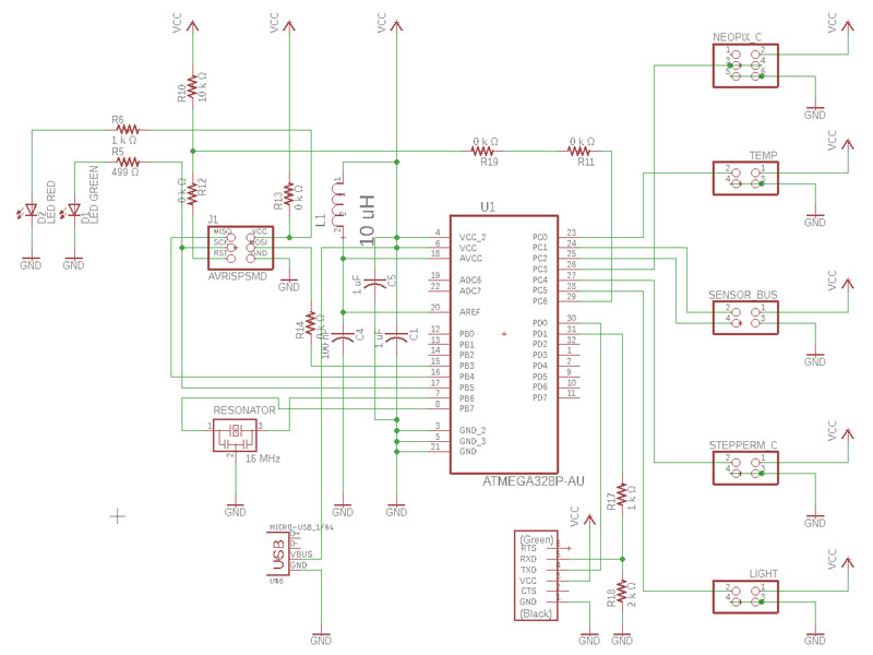
- FTDI -cable connected to ATmega328 -board // for powering the board // red LED is indicating that the board is powered
- ATmega328 -board connected to USBtinyISP -programmer // for programming the code that lights up Neopixels
- Power and ground -cables connected to NeoPixels strip // for powering the NeoPixels
- Neopixels strip connected to ATmega328 -board // for lighting up the LEDs based on the Arduino code
![]()
Programming NeoPixels
I took power for NeoPixels strip from the Fab Lab's electronic working station by turning on the working station and the power supply.
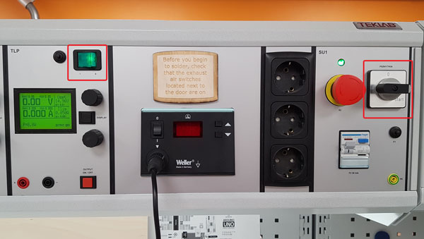
I adjusted the voltage and limited the current as follows:
- Voltage // 5.00 V (Volts)
- Current // 0.550 A (Amps)
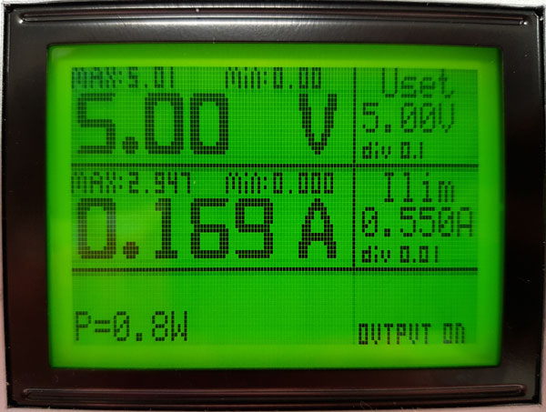
My own program for eight LEDs temperature rainbow used 0.169 A. The Output (the Power) needed was 0,8 W (Watts).
First, to test that my ATmega328 -board and its pin header etc, as well as the NeoPixels strip was working, I did a few tests with already made test codes obtained from the Adafruit NeoPixel -library .
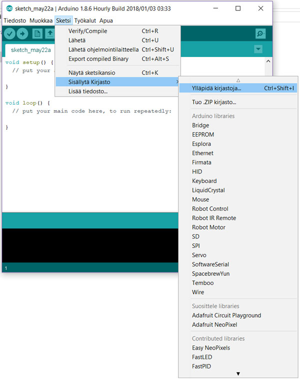
By navigating into a Sketch > Include Library > Manage Libraries I searched and downloaded the Adafruit Neopixel by Adafruit Version 1.1.6 -library which is a Arduino library for controlling single-wire-based LED pixels and strip.
![]()
Then, by navigating into a File > Examples > Adafruit NeoPixel > simple I opened this example code by Adafruit.
![]()
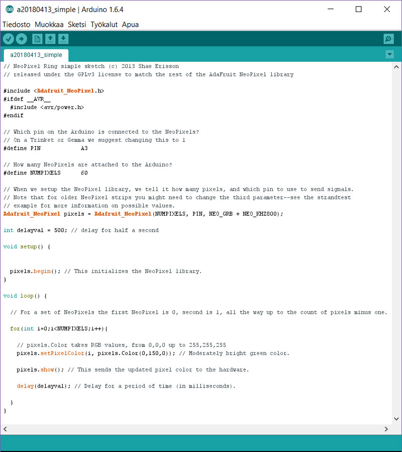
This is the simple from Adafruit NeoPixel Library, where I have modified the right output connection pin on my board and the number of NeoPixels I have:
![]()
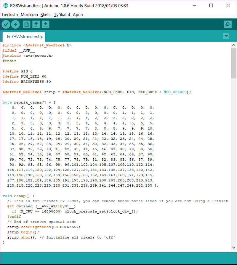
Further, I tested the RGBWstrandtest -example from the same Adafruit NeoPixel Library:
![]()
Then, for learning the code, first, I just changed the color of the LEDs in the first test code (c) 2013 Shae Erisson by changing pixels.Color(255,30,145));.
// NeoPixel Ring simple sketch (c) 2013 Shae Erisson
// released under the GPLv3 license to match the rest of the AdaFruit NeoPixel library

...
..

}
void loop() {

  // For a set of NeoPixels the first NeoPixel is 0, second is 1, all the way up to the count of pixels minus one.
  for(int i=0; i<NUMPIXELS; i++){

    // pixels.Color takes RGB values, from 0,0,0 up to 255,255,255
    pixels.setPixelColor(i, pixels.Color(255,30,145));  // Moderately bright fuchsia color.

    pixels.show(); 			    		// This sends the updated pixel color to the hardware.

    delay(delayval); 					// Delay for a period of time (in milliseconds).
  }
}
![]()
Then, I modified the code slightly and started to light up only some of the LEDs by assigning them separately instead of turning them all on pixels.setPixelColor(0, pixels.Color(255,75,0)); and did it one by one and in pairs using pixels.show(); in the end of the each single or pair of NeoPixels.
![]()
I ended up my experimenting with Adafruit NeoPixel library by finding the first set of colors for my final project, temperature LED screen.
First, I add acknowledgement and kept the defined libraries for the code.
// NeoPixel Ring simple sketch (c) 2013 Shae Erisson // released under the GPLv3 license to match the rest of the AdaFruit NeoPixel library // NeoPixel Strip sketch for max. 150 LEDs per one meter modified by Kati Pitkänen 17.4.2018 #include#ifdef __AVR__ #include #endif
Second, I modified the code and defined the pin the NeoPixel strip was attached: #define pinNeop A3, and the number of NeoPixels the strip has #define numberLEDs 150. Here, I set the amount of the whole strip but actually I could have reduced this number to eight since I was going to light up only that amount of NeoPixels.
  #define pinNeop             A3       // The pin on the Arduino connected to the NeoPixels for sending signals.
  #define numberLEDs         150       // Number of NeoPixels attached to the Arduino.
Third, I modified the line setting the number of NeoPixels, the connection pin, pixel type flags: NEO_GRB = Pixels are wired for GRB bitstream, and NEO_KHZ800 = 800 KHz bitstream (w/WS2812 LEDs).
Adafruit_NeoPixel pixels = Adafruit_NeoPixel(numberLEDs, pinNeop, NEO_GRB + NEO_KHZ800);
In void setup I defined the brightness of the NeoPixels to be 100% by pixels.setBrightness(100);
  void setup() {

  pixels.begin();                   // Initializing the NeoPixel library.
  pixels.setBrightness(100);        // Value from 0 to 100%
}
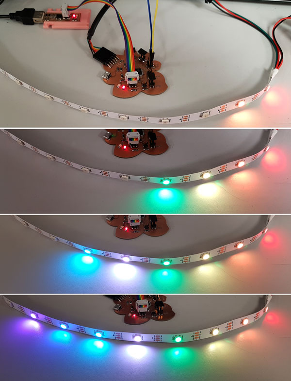
I assigned the first eight NeoPixels on the strip separately and gave it a color: pixels.setPixelColor(1, pixels.Color(255,75,0));.
Then, I made the NeoPixels light up in pairs by pixels.show(); and added a delay for a second between the pairs delay(delayval);, defined as int delayval = 1000;.
int delayval = 1000; // Delay for a second
The nice initial setting of colors I found by modifying the RGB values separately for red, green, and blue. I utilized the color picker inside the Photoshop CS6 to find the colors, but e.g. the web version on w3schools.com page does the same thing.
void loop() {

  for(int i=0;i<<>numberLEDs;i++){   // For a set of 150 NeoPixels the first NeoPixel is 0, second is 1,
  all the way up to the count of pixels minus one (150 - 1).

  // pixels.Color can take RGB values [from 0,0,0 up to 255,255,255 [R, G, B]]
  pixels.setPixelColor(0, pixels.Color(255,0,0));     // Red
  pixels.setPixelColor(1, pixels.Color(255,75,0));    // Orange
  pixels.show();                                      // Updating all the LEDs and sending the pixel color to the hardware.
  delay(delayval);                                    // Setting a delay for a defined period of time to change the next LED (in ms).

  pixels.setPixelColor(2, pixels.Color(255,255,0));   // Yellow
  pixels.setPixelColor(3, pixels.Color(0,255,0));     // Light green
  pixels.show();
  delay(delayval);

  pixels.setPixelColor(4, pixels.Color(255,255,255)); // White
  pixels.setPixelColor(5, pixels.Color(0,255,255));   // Light blue
  pixels.show();
  delay(delayval);

  pixels.setPixelColor(6, pixels.Color(0,55,255));    // Blue
  pixels.setPixelColor(7, pixels.Color(75,0,255));    // Purple
  pixels.show();
Now, I have the first understanding about programming NeoPixel strip in general and I can continue further and familiarize myself with programming the temperature graph and thus, present several values at the same time on my temperature LED screen.
Learning some principles of electricity
This week I calculated the current for NeoPixel serial lightning, and made a table for the basic principles of electricity to understand and learn them better.

In Finland, we have a mnemonic called PUIMURI containing the basics of electrical engineering. Here is the explanation of the mnemonic obtained from the Harraste Elektroniikka website (in Finnish, though):

Ohm's Law // (U = R * I) // Describes the relationship between Voltage, Current, and Resistance:
- Voltage across a resistor (in volts) = The Resistance of the resistor (in ohms) * Current through the resistor (in amperes)
According to Adafruit Tutorial, the amount of current (I) going through an LED is directly proportional to how bright it appears - by increasing the current, the LED will be brighter, and vice versa. They are advicing also, that for 99% of LEDs the optimal current is 20 milliAmperes (0.02 A) but it is possible to push it up to 30 mA if a little more brightness is needed.
Moreover, Kirchhoff's circuit law and more spesific the Kirchhoff's Voltage Law (KVL) deals with the (forward) voltage (also called Kirchhoff's second law). The Kirchhoff's Voltage Law in practice means, that "In any 'loop' of a circuit, the voltages must balance: the amount generated = the amount used" (Adafruit).
Adafruit has nice tutorials, such as this Forward Voltage and KVL and Powering NeoPixels for learning to calculate the voltage and power my NeoPixel strip.
Estimating Power Requirements
My NeoPixels' acceptable voltage limit is DC 5 Volts, so I can use 5V DC switching power supply to power my NeoPixel strip. (However, lower voltages are always acceptable, with the caveat that the LEDs will be slightly dimmer.)
From Adafruit tutorial I found the information, that each individual NeoPixel draws up to 60 milliamps at maximum brightness white (red + green + blue). (But in actual use, it’s rare for all pixels to be turned on that way.) On the tutorial they say, that it is impossible to estimate a single number for all circumstances. So, if there is no need every pixel on at maximum brightness, they have been using 1/3 of max (20 mA per pixel) as a gross rule of thumb with no ill effects.
In my case this could be:
Number of NeoPixels x mA/ each = Current needed in total
- (150 NeoPixels × 20 mA) = 3.0 Amps minimum
- (10 NeoPixels × 60 mA) = 0.6 Amps minimum
Since I aim to lit up 10 NeoPixels at a time, a power supply of DC 5V 1A or 2A should be good.
From the Tutorial I found also the answer to my further question:
"I estimate I need a 3.6 Amp power supply. I have a 10 Amp supply on-hand. Will this cause my NeoPixels to explode?"
- "As long as the output is 5 Volts DC, you’re golden. The LEDs will only draw as much current (Amperes) as they need. So extra Amps are OK — in fact, it can be a good thing. The larger power supply will run cooler because it’s not being pushed to its limit."
BUT !!
- "Excessive voltage, however, will definitely kill your LEDs.
- EXTRA AMPS = GOOD. EXTRA VOLTS = BAD."
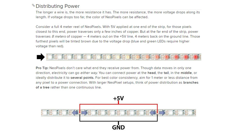
More over, here is good description on resistance, voltage drops, and Distributing Power.
Here is the programming code for my NeoPixels I programmed this week.
Here are the files of my ATmega328 Flower -board and the sensor boards I made on the Week 12.
- Schematic in sch format
- Board Layout in brd format
- The Traces (changed from png to jpg format when reduced the size)
- The Outline (changed from png to jpg format when reduced the size)

