
Kati Pitkänen @ FAB LAB OULU · 2018
© 2018 Kati Pitkänen · Template by Bootstrapious

This work is licensed under a Creative Commons Attribution-NonCommercial-ShareAlike 4.0 International License.
Computer-controlled machining
Week 8 · [ 7.3.2018 - ]
- Test runout, alignment, speeds, feeds, and toolpaths for your machine (Group Project)
- Make something big (on a CNC machine) (Individual Project)

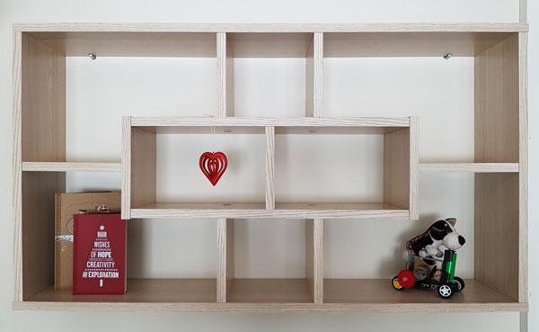
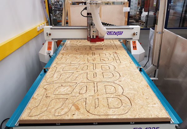
This week I designed a shelf to our livingroom. The material I used is OSB (Oriented Strand Board) which thickness is 11 mm.
I was really excited to make something big and learn to prepare and use a CNC router. I found CNC very useful machine, and I would like to explore more of its advantages, where it can cut thicker materials than a laser cutter, as well as mill rounded surfaces.
This time, I preferred the aesthetics in my design model. When considering afterwards, it didn't make sense that I was doing computer-aided design and computer-controlled cutting but then the finishing and sanding phase took more time than necessary. The problem was mainly in my design, since I wanted to try normal 90 degree sharp corners in joints and avoid so-called dogbones (the name comes from the form, when the circles are added to the corners for letting the round milling bit reach the corner fully) in the corners. What I would change for the next time is, that I would keep the front and the back slices as they are, but I would use the dogbones in the invisible parts of the middle layers.
What I succeeded in was the holes for the hooks on the back side of the shelf, which turned out to be perfect. Since there was already the hooks on the stone wall I was going to place the shelf, I had to be very precise in my measuring and designing the pockets to cut, and I was very satisfied with the result.
I was also glad to utilize and learn more about Inventor thanks to our local instructor Eino Antikainen. So far, I have used it only for a short time so, there was a lot of nice new things to learn in the Assembly -feature.
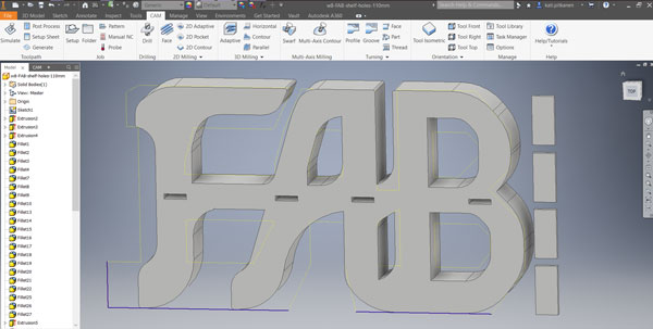
2D and 3D designing in Inventor
I got an idea of making a shelf consisting of slices. In that way, I was able to use the forms I wanted to instead of sticking to traditional forms. I started by taking the measurements of our existing shelf (and its hooks on the stone wall) which I was going to replace by the self-made one.
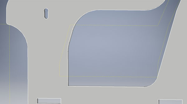
First, I set the parameters including height (500 mm) widht (869 mm), and thickness (110 mm - being 10 times of the thickness of the material, 11 mm) and designed a 3D -model of the shelf with Autodesk Inventor "Part" design in order to see how it would look like in real. I considered to assebmle the shel by four simple horisontal joints so, I added holes (11 mm x 50 mm) and created chocks (11 mm x 50 mm x 110 mm) to fit in them.
Then, I modified the 3D -model by extruding it to different directions horisontally and creating cut files layer by layer. The first eight layers are identical, and the last two include the holes for hooks, which will be slided into holes.
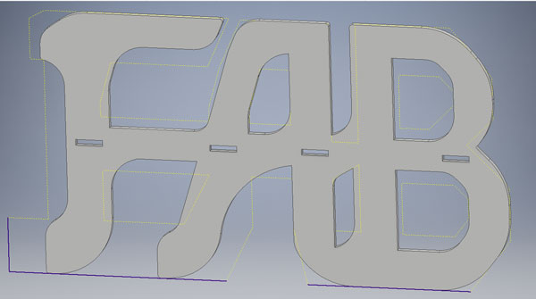
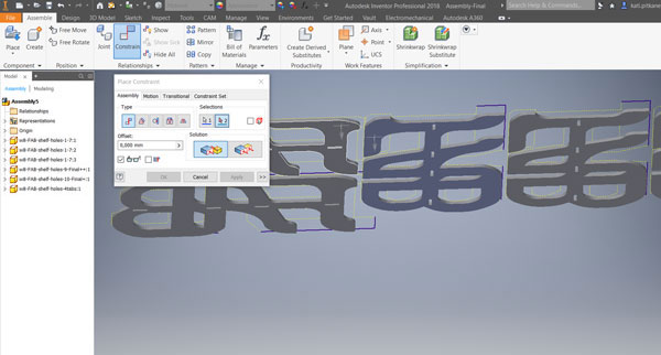
2D Assembly in Inventor
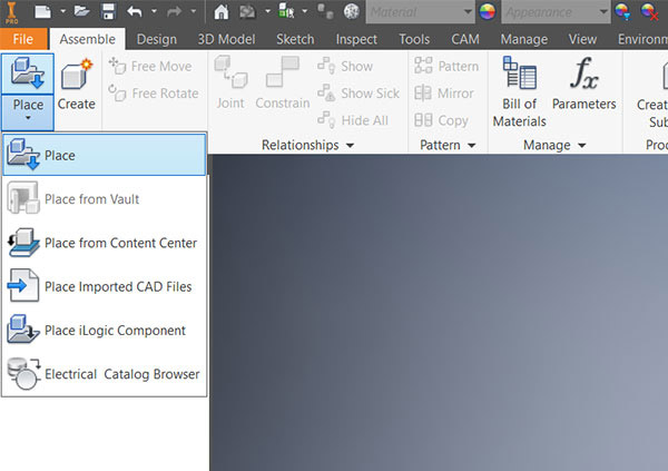
I created the file composition to be cut in Autodesk Inventor "Assembly" design, by navigating in the top bar File > New > Assembly.
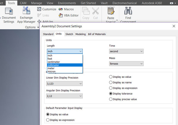
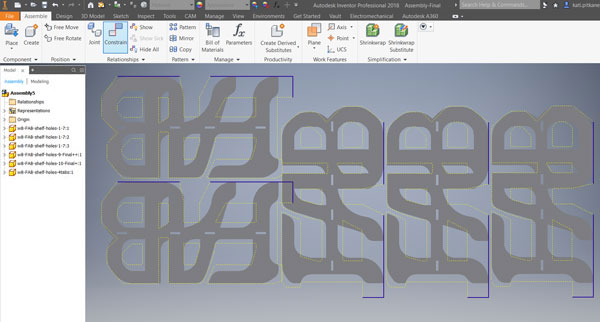
First, in Tools > Document Settings, I defined the units to be millimeters. Then, I specified the files to place as a component in an assembly. By navigating in the top bar Assemble > Place > Place I placed 10 slices consisting the shelf and four joint chocks on the two OBS -shields to be cut.
I aligned the slices to be in line and in the same plane, as well as having enough space between the parts for the milling bit to run by Assemble > Constrain -tool.
CAM in Inventor
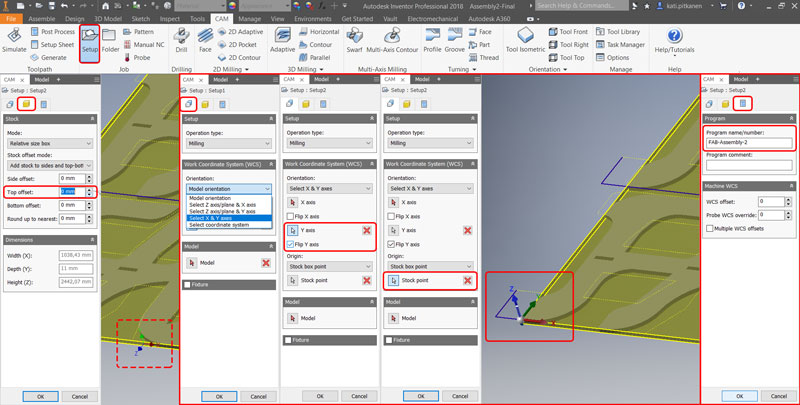
For doing the Setup, I navigated in the top bar to the CAM -tab.
First, I defined general properties for a set of machining operations in the Setup -tab.
- STOCK // Side offset: 0 mm, Top offset: 0 mm (Specifies the additional stock on the top - my design didn't need any)
- SETUP // Operation type: Milling
- SETUP // Operation: Model orientation - 'Select X & Y-axes', activate the box according to which axis you want to define, and select the correct axis from the design. Flip if needed.
- SETUP // Stock Point: Select a point on the yellow Stock Box to set the origin of the design - I took left bottom corner.
- Now, the origin should be on the bottom left corner, where Y-axis points forward, X-axis to the right and Z-axis to the up.
- POST PROCESS // Program name/number: Here you are able to name your milling program for a current assembly file already at this phase.
- Press 'OK' and the Setup -file appears to the list of Operations in the CAM -tab.
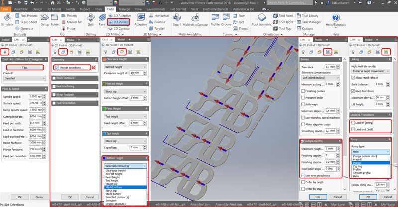
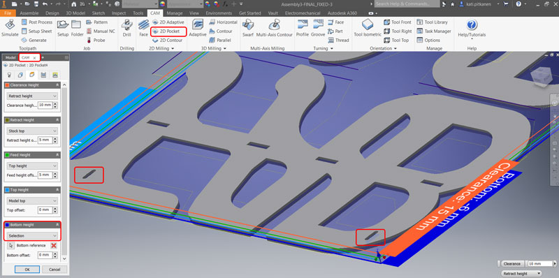
Creating the roughing operation of 2D Pockets
Next, I created a roughing operation that uses toolpaths parallel to selected geometry in the 2D Milling -tab.
- TOOL // Select 'Tool' - in this case Ø 8 mm Flat Mill. ***)
- GEOMETRY // Do the 'Pocket selections': when the tool is activated, select the pockets, which are intended to be milled away fully, and having the same height.
- HEIGHTS // Top Height: Model top, Bottom Height: either 'Model bottom' if the pocket goes fully through OR if it will be gouged, 'Selection' and choose the correct bottom layer from the design. Rotate the design preview to see, that heights of the Top and Bottom look correct.
- PASSES // Select: Multiple Depths, set Maximum roughing stepdown to 3 mm, and select 'Use even stepdowns'. Unselect 'Stock to Leave.
- LINKING // Unselect both Lead-in (entry) and Lead-out (exit) (are for metal, not for wood). Select Ramp type: Plunge (for wood.
- Press 'OK' and the Pocket -file appears to the list of Operations in the CAM -tab.
HOX. Multiple Depths are selected because, when cutting with full width of the milling bit, the height needs to be devided and cut in several layers (vs. cutting from the edge), otherwice it is too much force for the tool.
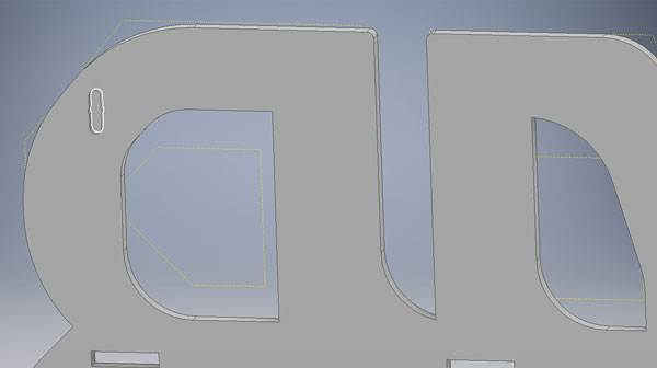
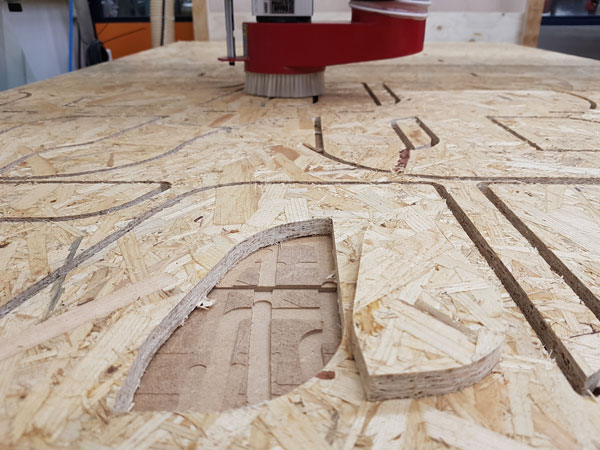
I had a couple of cuts in my design which were not meant to cut through but gouge the surface:
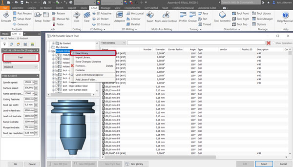
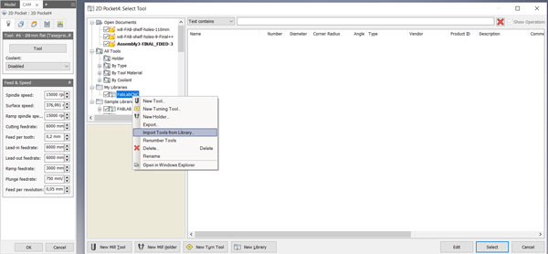
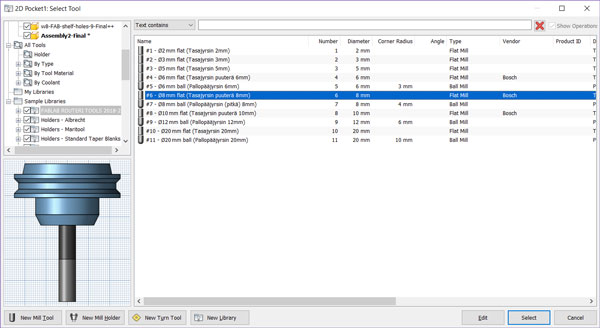
***) When selecting the tool, especially for the first time, you need to know what are the tools available. In this case, Fab Lab has its own tool library: FABLAB ROUTERI TOOLS 2018-2.hsmlib which I dowloaded and stored in the specific folder. When I was doing Pockets, I selected 'Tool', where I had to define which library and tool I will use. Then, by right-clicking on top of the 'Sample Libraries' I created:
- New Library > Import Tools from Library > Navigate the library and press 'Open'.
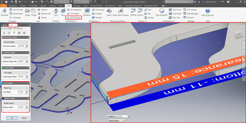
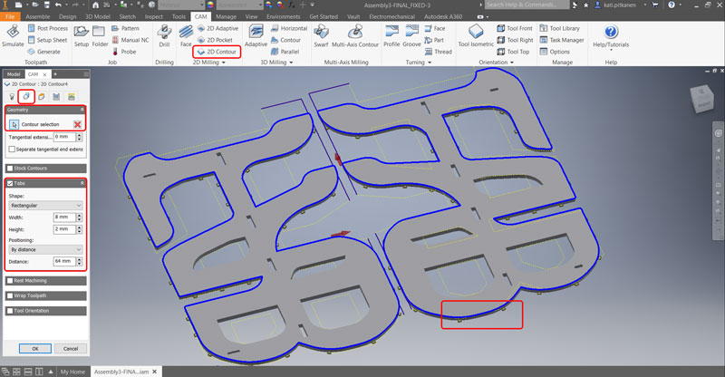
Creating the roughing operation of 2D Contours
Further, I created toolpaths based on the 2D contour in the 2D Milling -tab.
- TOOL // Select 'Tool' - in this case Ø 8 mm Flat Wood Bit. ***
- GEOMETRY // Do the 'Contour selections': when the tool is activated, select the contours of the design (both edges and bigger "pockets"), which are intended to single out-cut from the material.
- GEOMETRY // Select: Tabs, and set Width 8 mm and Height 2 mm (these values are fine with OSB).
- HEIGHTS // Top Height: Model top, Bottom Height: 'Model bottom'. Rotate the design preview to see, that heights of the Top and Bottom look correct.
- PASSES // Select: Multiple Depths, set Maximum roughing stepdown to 3 mm, and select 'Use even stepdowns'. Unselect 'Stock to Leave.
- LINKING // Unselect both Lead-in (entry) and Lead-out (exit) (are for metal, not for wood). Select Ramp type: Plunge (for wood.
- Press 'OK' and the Contour -file appears to the list of Operations in the CAM -tab.
Convert the machine-independent cutter location data into machine-specific NC code in the Toolpath -tab.
Select all of the operations (pockets and contours) done and visible on the CAM -operations list - Note that the operation paths will be done only for the selected operations!
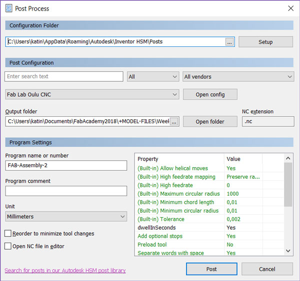
In the top bar, navigate to Toolpath > Post Process:
- When doing this for the first time, I had to check the Configuration Folder, and download and add the CAM post processor file for Autodesk Inventor/ Fusion360: FabLabCNC.cps into that folder.
- Set Post Configuration // Fab Lab Oulu CNC
- Define Output folder
- On Program Settings you can see the name of the program you gave earlier, or rename the program.
- Select document Unit // Millimeters
- Press Post and the NC code will be generated.
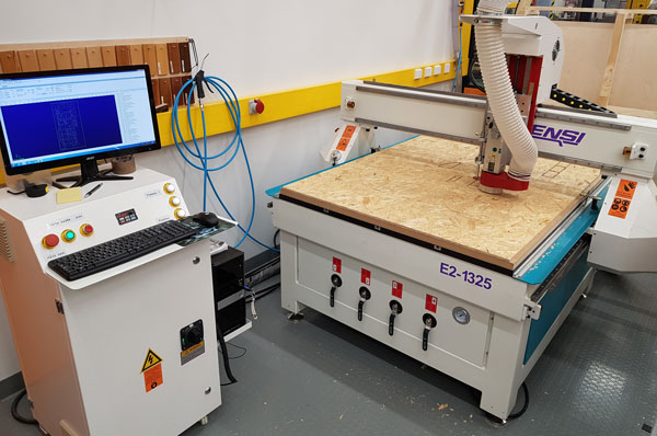
Prepare the CNC Machine
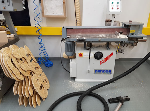
The CNC machine I used to cut the shelf is RE2-1325 CNC Router With Linear ATC, for which we got very good guidance from our local instructor Eino Antikainen.
Computer
- Switch ON.
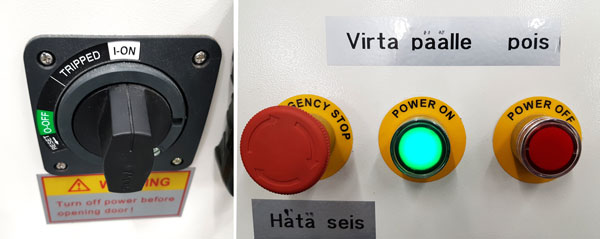
CNC Machine
- Switch the main switch I-ON.
- Turn the Power ON.
Before inserting the material make sure that:
- The material is big enough for the design.
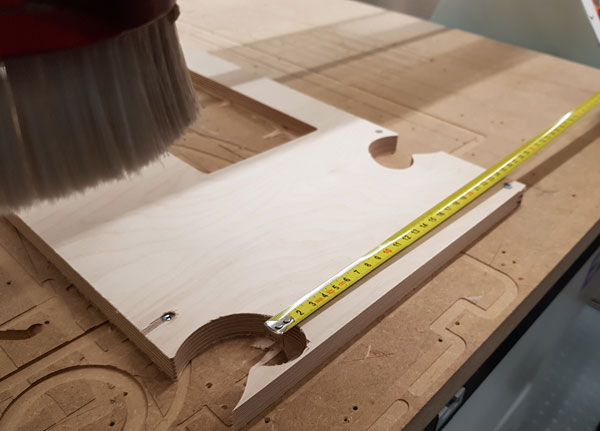
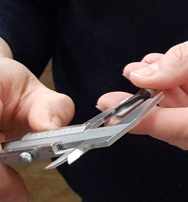
- The thickness of the material is aligned with the design by measuring it with a caliper.
- The vacuum of the sacrificial layer is fine and the bed is straight.
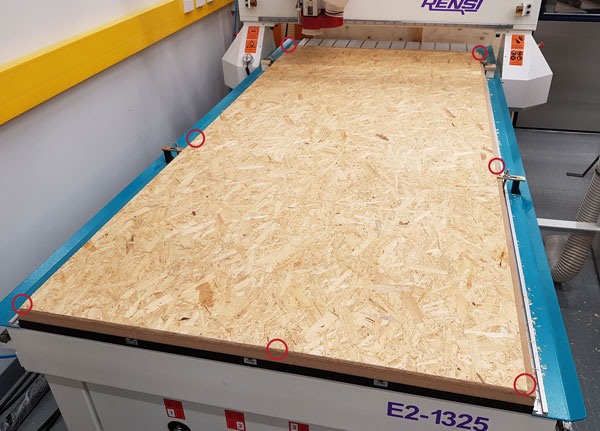
- Then, insert the the material and fix it by screwing it to a sacrificial layer at least from the corners, and from the middle of the sides (depending on the material and a size of the sheet, of course). Check carefully the length of screws in order to avoid attaching them through the sacrificial layer to the vacuum bed!
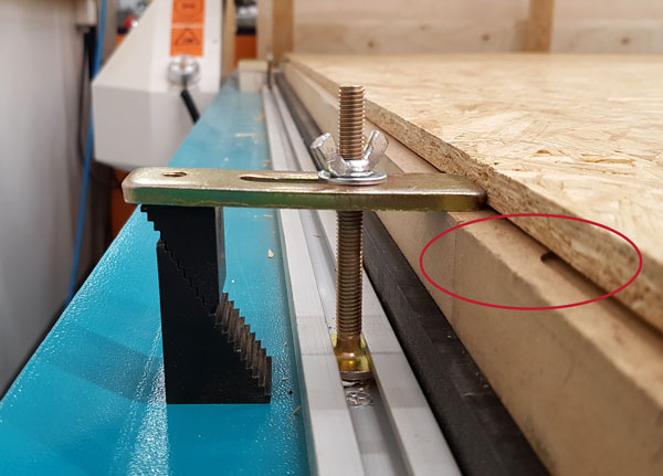
In case the sacrificial layer does not vacuum well or there is difference between the layer heights fasten the layers with clamps.
Make sure that the sheet is not bended being in the air but is attached well to the sacrificial laeyr. Add screws if necessary.
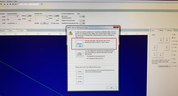
In case the machine was shut down, always build the Mechanical Coordinate after software starts up by selecting 'All Axes' from automaticlly opening pop-up window. The program will move all axes to the Mechanical Origin in order Z, X and Y axs. After it is finished, press 'OK'.
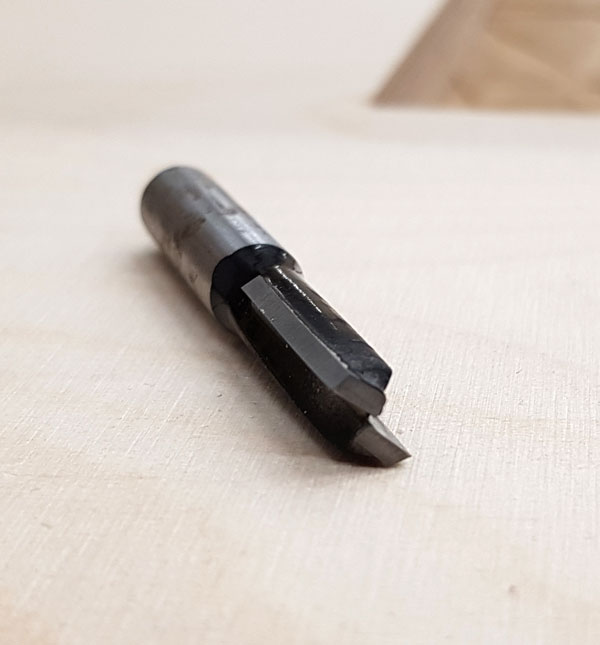
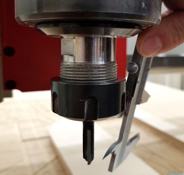
Insert the milling bit, which in this case was a Ø 8 mm Flat Wood Bit.
- Just to make sure, measure the diameter of the bit by caliper.
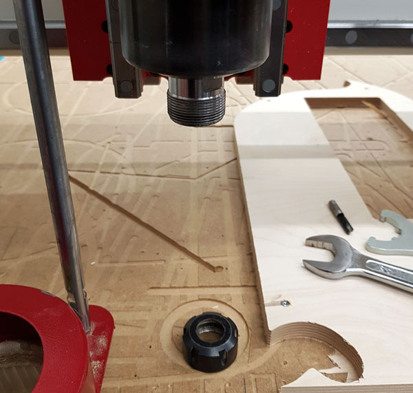
- Locate the milling head close to the edge for inserting or changing the milling bit.
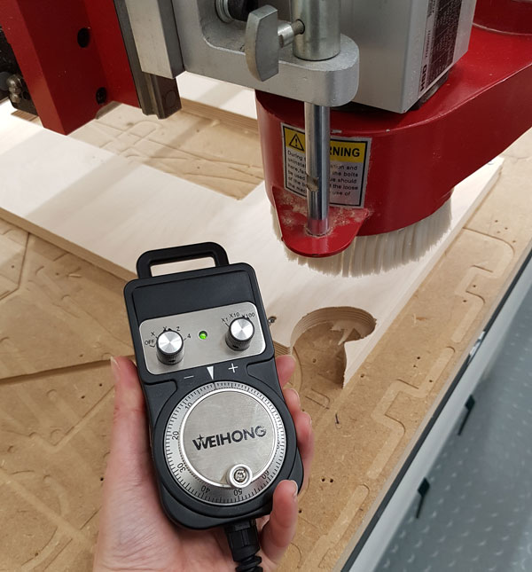
- The axes can be moved manually either by Handwheel or Jog (+/-).
- When doing manual 'Jog', by pressing Ctrl the axes will move quicker.
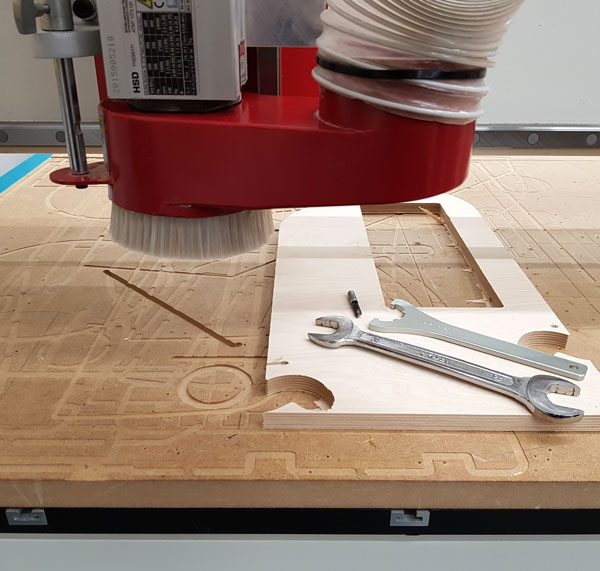
- Open the tension screw on the left side of the milling head and drop down the dust collctor head.
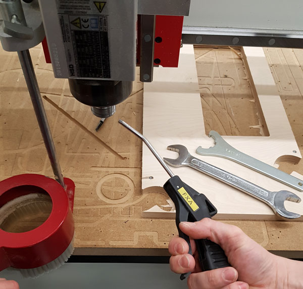
- Use a 27 mm open-end wrench and another special tool to open the power coat nut, and clean the head with compressed air.
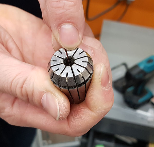
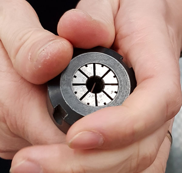
- Insert the collect chuck to the power coat nut.
- Find the collet chuck (socket) where the milling bit will be attached and clean it with compressed air.
- Insert the collet chuck (with or without the milling bit) to the nut, put them to the holder, and fasten the nut.
- Measure, that there is enough milling bit visible compared to the material that will be cut.
Adjust the X- and Y- axes:
- Move Z-axes close to the surface, find the suitable place for X- and Y-axes' origin - make sure to avoid the top of the screws! - and reset the axes to be 0.00 mm by clicking the buttons next to the coordinates in the software.
Adjust the Z- axis:
- 1) Manually by a handwheel, when moving the milling bit very slightly down until it reaches the surface of the material, and reset it to be 0.00 mm by clicking the button next to the coordinates in the software. Then raise the milling bit a little bit up so it has space to speed up the spindle speed before touching the material.
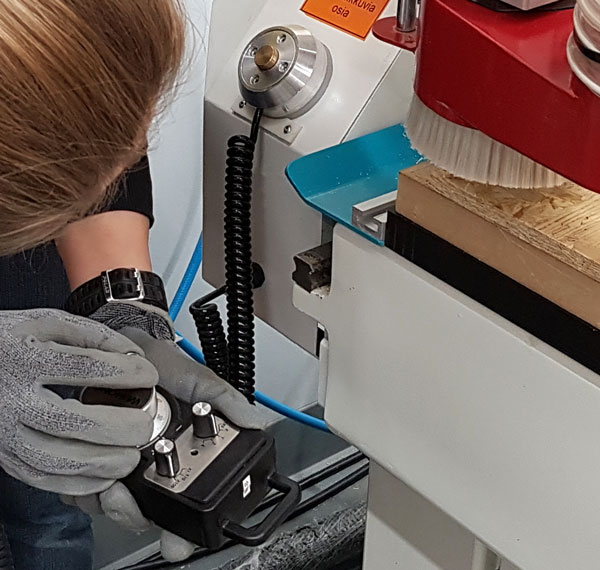
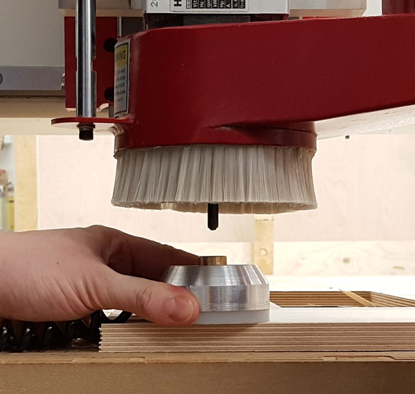
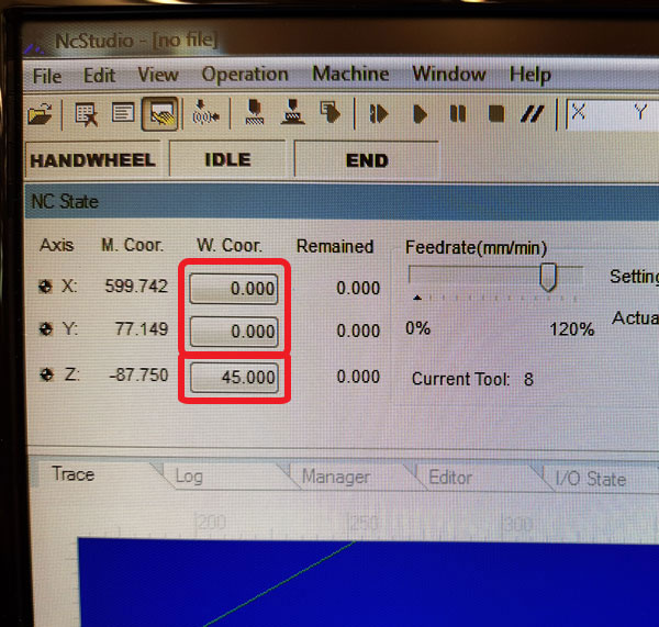
- 2) Automatically by navigating in NC Studio top bar Operation > Mobile Calibrator. In that case, the calibrator tool (height 45.00 mm) will be used and added below the milling bit. 'To perform a calibration action', press OK (Kyllä) and the milling bit will come down slowly until it touches the surface of the calibrator, and automatically resets that height to be 45.000 mm.
There are two possibilities to adjust Z-axes:
Now, the X- and Y -axes are set to 0.000 and Z-axis either 0.000 (by manual) or to 45.000 mm (using calibrator).
Cutting with the CNC Machine
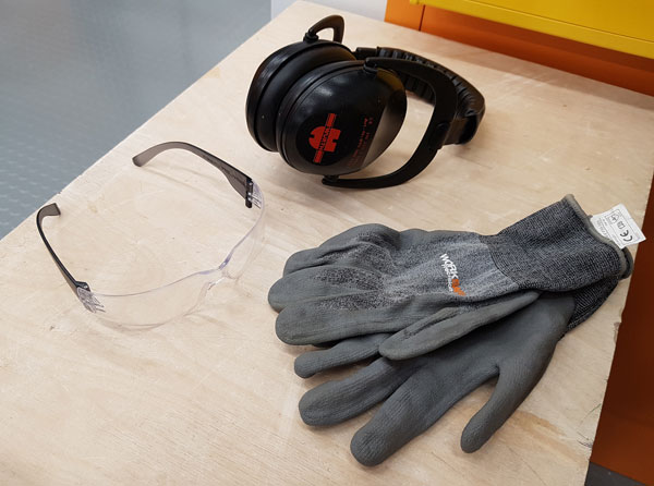
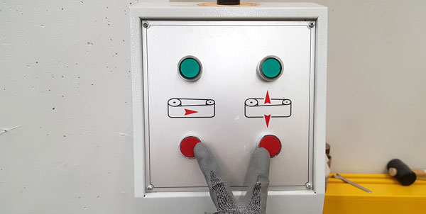
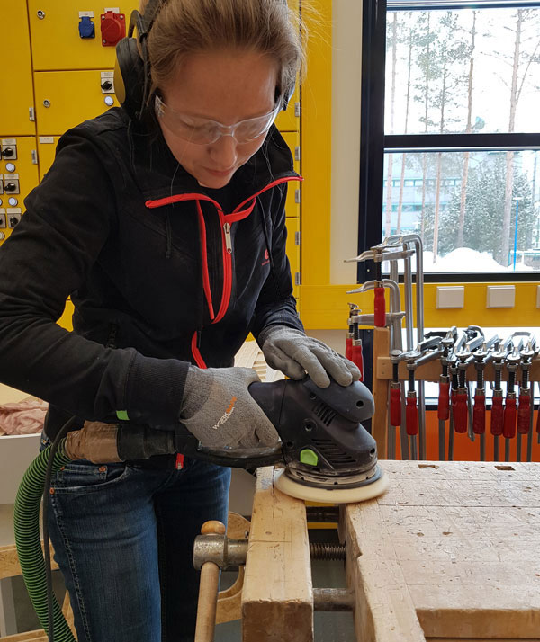
Ensure that you wear appropriate protection accessories.
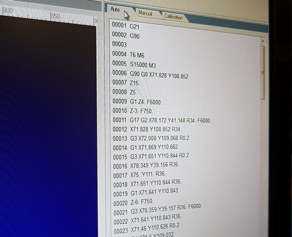
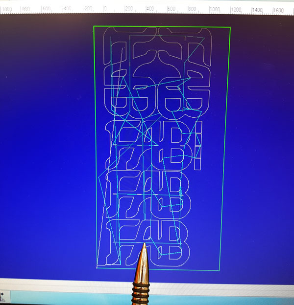
- In the top bar of NC Studio, navigate to File > Open and Load and find the file to be cut. Check the Auto -tab that the NC code is loaded.
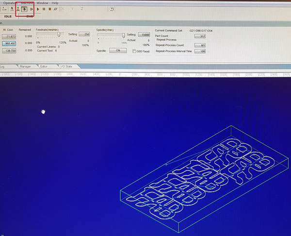
- Clear the view by right-clicking on top of the blue constructing are and select Clear.
- Navigate to the top bar and Simulate the job to make sure that everything looks correct and will be cut as designed.
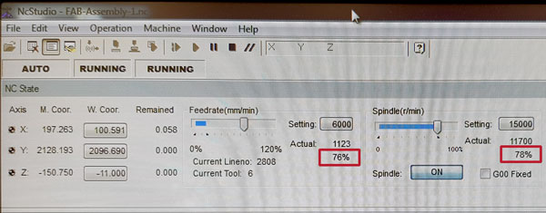
Set both the starting speed of Spindle (r/min) and Feedrate (mm/min) to be around 80 % of maximum. These can be adjusted during the cutting based on performing of the machine. However, start from around 80 % since it is easier to slow down than increase the speed.
Switch ON the two Vacuum Pumps and the Dust Collector.

Start cutting by pressing PLAY symbol in the top bar. Follow the performing, and adjust the Spindle and Feedrate if necessary.
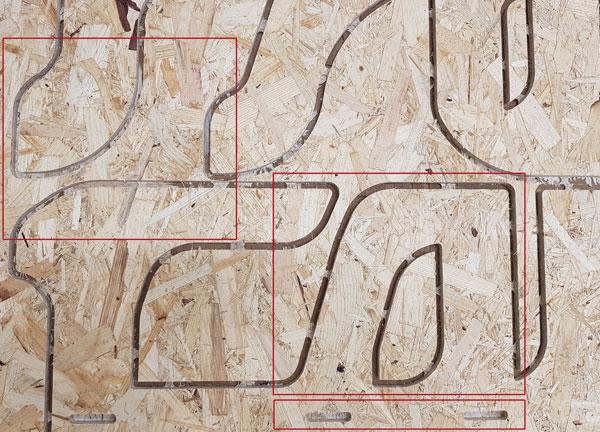
A Problem encountered: When cutting the first sheet, the two sacrificial layers were not fully vacuumed and consistent with each other so, there was a difference in height of the bed: +0,3 mm in the middle and + 1,3 mm in the back of the sheet when compared to the origin.
This caused not only variety in the cutting result but also, breaking some of the tabs, which caused a risk of adrift material getting stuck into the milling bit or movement during the milling.
The problem was solved by adding four clamps for strengthening the vacuuming.
Also, the material we used, OSB, is not that good or uniform quality, which was seen in the cutting results as well. Afterwards, when measuring, the thickness of the material in the same sheet varied between 11 mm - 11,5 mm, and between the sheets, it was almost 1,5 mm where the difference was already tangible.
After the file is cut, do the opposite than in the start:
- Turn off the Vacuum Pumps and Dust Collector.
- Turn the Power OFF and
- Switch the Main Switch 0-OFF.
- Remove the material and clean the area.
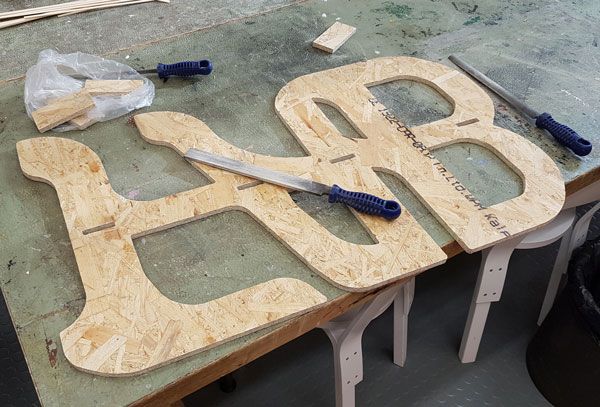
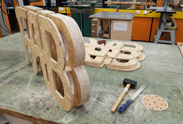
Assembling and finishing
For esthetical reasons, I decided to not make 'dogbones' so, more sanding to make the corners of the holes for joint choks sharp. Later on, I thought, that I could have made the dogbones for inner slices and the sharp corners only for the outer slices, tough.
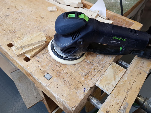
Sanding joint chocks.
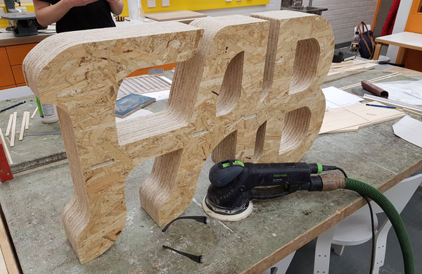
Putting everything together slice by slice.
Final sanding left anymore, to make the surface smooth and change the color to be a little bit lighter:
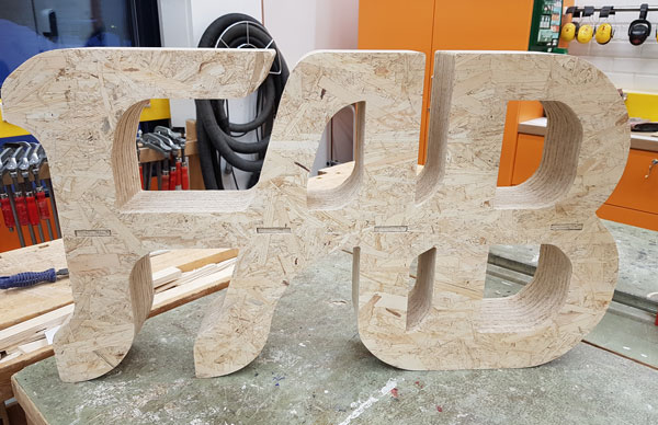
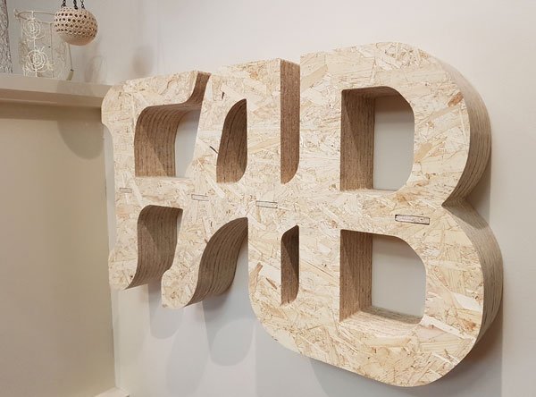
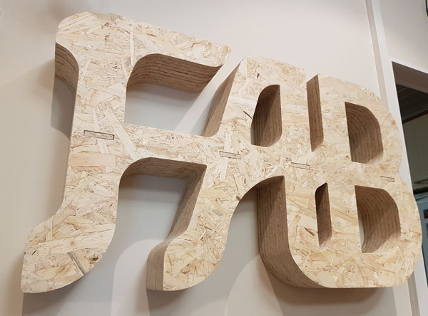
The FAB -shelf on the wall!
Check the sacrificial layer carefully, that it is fully vacuumed - and if several layers, that they are aligned with each other. If not vacuumed enough, fasten it with clamps.
Listen to the CNC Machine and adjust the spindle and feedrate. The feedrate has to be high enough for effective milling take If there is too much spindle speed and too less feedrate, the bit takes only little material away.
For the very small pieces, add more tabs to ensure them stay without breaking during the cutting.
The group familiarized itself of the advantages and limitations of CNC Machining by the group work tests by testing runout, alignment, speeds, feeds, and toolpaths for our machine.
Here is the ZIP-package of The FAB Shelf I made this week containing the following files:
- The design files in Assembly iam and Part ai formats
- The 3D models in stl format, and
- NC codes for CNC Machine