
Kati Pitkänen @ FAB LAB OULU · 2018
© 2018 Kati Pitkänen · Template by Bootstrapious

This work is licensed under a Creative Commons Attribution-NonCommercial-ShareAlike 4.0 International License.
Computer-Aided Design
Week 3 · [ 31.1.2018 - ]
- Model (draw, render, animate, simulate, ...) a possible final project, and post it on your class page with original 2D and 3D files.
- Evaluate and select 2D and 3D software
- Demonstrate and describe processes used in modelling with 2D and 3D software
This third week was very busy to me, because on that week I moved from Denmark back to Finland after five fantastic months internship in Fab Lab Silkeborg and FabLab@SCHOOLdk. I enjoyed the company of the guys in FabLab Spinderihallerne with whom I started my Fab Academy path, and I very much appreciate their local instructor Lorenzo Negri helping me to get started - as well as the guys at home, at Fab Lab Oulu, who welcomed me warmly to the group. However, I was late from the schedule and finally, I managed to finish this week assignments right before summer.
The positive side in this was, that because my first final project idea (a rack for 3D scanner) changed during the spring period, in the end I could use this week for designing the parts for my new final project idea. Moreover, it was nice to look back and evaluate and define some advantages, limitations, and differences between the 2D and 3D modelling software.
I have experienced that Adobe Illustrator is a neat program for 2D modelling. However, compared to the free and open source vector graphics editor Inkscape, I have to say that Inkscape has a lot of useful, nice functions and extensios to utilize, for instance Tabbed Box Maker and Gear -extensions. However, it is not a CAD program and its limitations will be visible when e.g. moved further and on creating a g-code for CNC machine and noticing, that not all of the vector lines are fully connected.
There is a great difference in 3D modelling softwares too, where Autodesk Tinkercad works very fine on experiencing and learning three-dimensional thinking and modelling. Autodesk Fusion 360 and Autodesk Inventor have more similar structure and content together, but the difference in using them is significant. Fusion 360, which is in between the other two, looks and feels simplier because it is more visual, and neat software. However, even the logic has some similarities, it is somehow different compared to the Inventor, and this is why I have found Inventor more logical and enjoyable to use. Anyway, the latter two are both fine, and in the future I might found myself using the one that fits best for my purpose. Moreover, I would like to test also other software ouside this family, such as SolidWorks.
2D Designing and Modelling
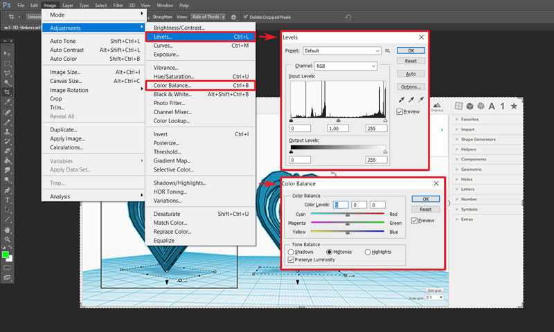
For editing the screenshots on my documentation I have used Adobe Photoshop CS6 software (raster). Photoshop is a software creating and enhancing photographs, illustrations, and artwork.
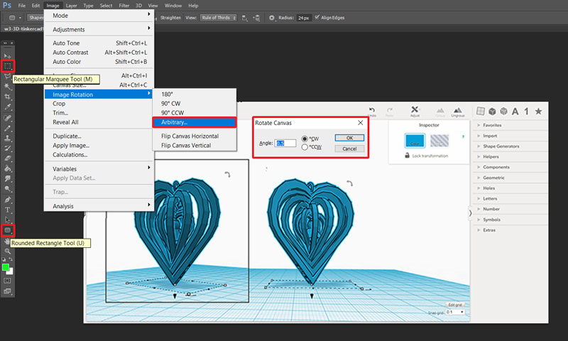
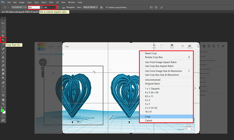
The basic features I use for editing pictures are, at first, the appearance of the picture, so to make the horisont horisontal and not out of line. To straighten the picture I navigate into top bar Image > Image Rotation > Arbitrary where I can set the angle of how much the canvas should be rotated. To finish the canvas, from the left tool bar, I select Crop Tool to mark off the edges, and by right-clicking the mouse hit Crop.
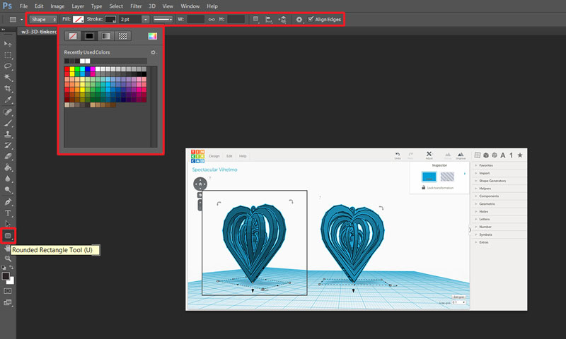
I use Rectangular Marguee Tool e.g. to copy some details on the picture to the same or some another picture - such as I have copy-pasted the small rectangular piece from another screenshot here to show two perspectives on the same heart object at one picture. I have marked off the edges of the copy-pasted picture using Rounded Rectangle Tool and selecting the properties of the rectangle from the top bar.
Second, I focus on the content, the lightness and the color of the picture. I adjust the values by navigating into the top bar Image > Adjustments > Levels / Color Balance.
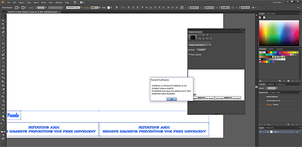
In 2D modelling, I have tried using Adobe Illustrator CS6 (vector), which is documented briefly on the Week 4.
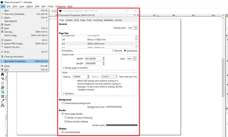
My first idea for the final project was to make a rack and holder for 3D scanner to get better scanning results. To design a 2D model of a rack I used Inkscape (vector). Inkscape is described to be a professional, free and open source vector graphics editor.
First of all, from the top bar, by navigating in File > Document properties I changed the page size to be A1 (841 x 594 mm) to have space enough for my design.
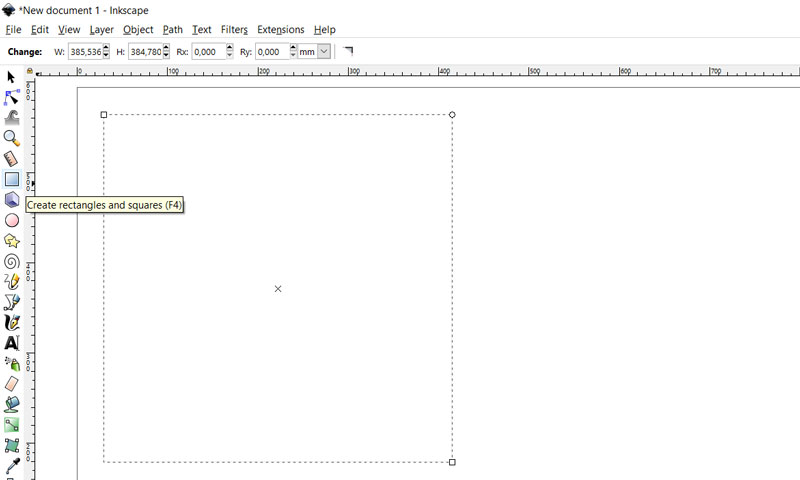
I designed the parts which I considered to be done in 2D, involving the horisontal leg part, gears, and a rack standing for keeping and moving the 3D scanner. To design the leg, I selected from the left tool bar the Create rectangles and squares -tool. I considered creating the leg in a form of a square to make it stable, but e.g. a cross could have been worked as well and save some material.
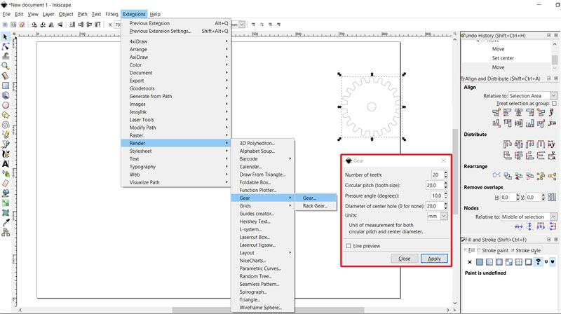
I continued by creating a circle using Create circles, ellipses, and arcs -tool to be the plate for object to be scanned. Next, I created the gears to make the rotation of a rack for 3D scanner using Gear extension for Inkscape, and defining the details of the gears and further, I designed the rest of the 2D parts of the track as well.
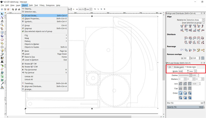
In the end, it is important to check the final size of all parts. In this case, specially size of the hole in the middle of the parts, where the bar holding the parts together is located. Another important thing is to make sure that the Width of vectors that are meant to be cut (instead of rasterizing them) have to be 0,02 mm: Object > Fill and Stroke > Stroke Style -tab > Width: 0,02 mm.
Note: I still have to consider, if I will automate the rotation of the track only or instead of tightening the 3D holder manually 'side' and 'up' positions, automating also that one to move by gear.
3D Designing and Modelling
To evaluate and select software for 3D modelling I have experienced modelling with Tinkercad, Autodesk Fusion 360, and Autodesk Inventor.
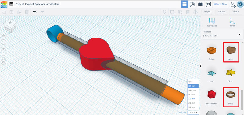
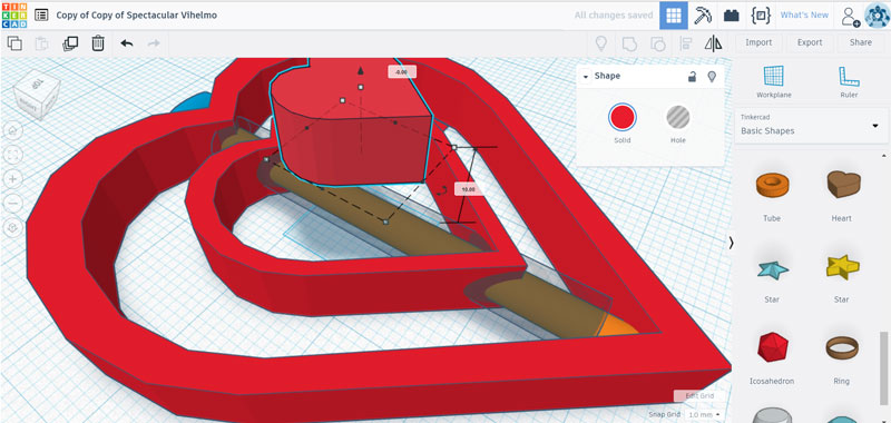
Tinkercad is a simple, fully free online 3D design and 3D printing app. Using Tinkercad it is easy to learn the principles of 3D -modelling. I have experienced using it by testing the basic functions of it. First, in the bottom right corner, I will set the Grid to define the precision to move the objects on the canvas. With dragging and dropping the Basic Shapes it is easy to practice three-dimensional-dimensional thinking and modelling.
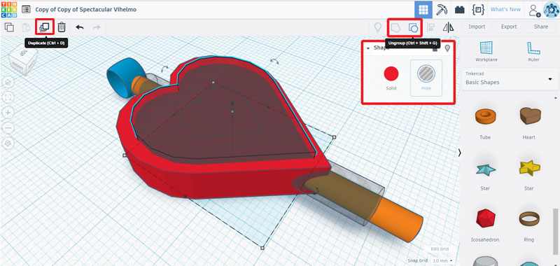
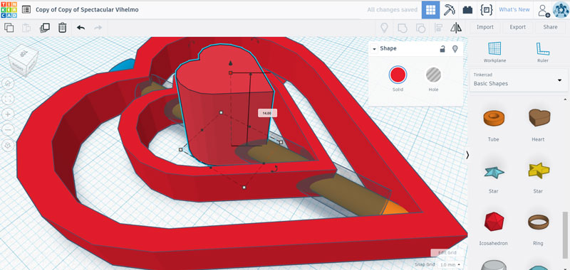
The objects can be modified easily by either dragging and dropping or activating the object and setting the value in chancing size, or multiplying shapes, or adding holes inside the solid parts, and further, by grouping/ ungrouping solid and hole -objects.
For chancing the location or size of the object, I will activate it and either drag it or set the parameters to define the new location or the new size.
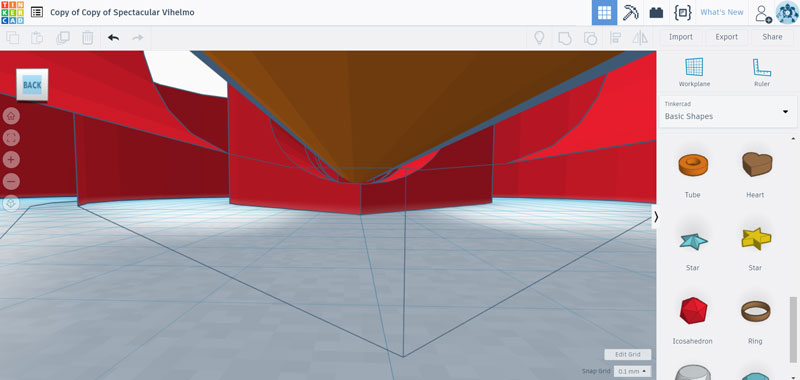
The thing I like in using Tinkercad is, that a user can go and have a look inside the object, and the part the user is inside will change to be transparent for a while, so it can be e.g. checked manually, if the parts are connected/ separated.
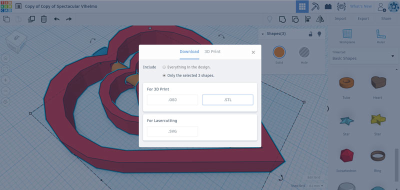
Finally, I selected all the parts by dragging over them, navigated into Export on the top right corner and selected that I wanted to Include: Only the selected 3 shapes to create a stl file (and not the possible drafts around the actual object).
In 3D modelling I have experienced using Autodesk Fusion 360 as documented on the Week 10. Fusion 360 is said to be the next step after experiencing using Tinkercad, because it has much more functions than Tinkercad, but its user interface is more visual and simplier when compared to the third step, Autodesk Inventor.
Fusion 360 has its advantages compared to Inventor. For example, it is possible to import a vector file in svg format to Fusion 360, and then simply extrude the object, but I haven't manage to do that in Inventor. Also, it is possible to create very nice simulations on Fusion 360. In a way, the history tree in Fusion is simplier too, because it won't group and "hide" the history but keeps everything visible. However, for me Inventor is in many ways more logical and enjoyable to use, so I used that software to model the part for my final project.
My choise for 3D modelling in this phase is Autodesk Inventor. It has a great variety of functions to learn and utilize, and for me, it has seemed to be the easiest one to learn and work with. I like the user interface of it, navigating into the menu, and history tree etc much more than in Fusion 360, which is easier to use after experiencing Inventor, but still somehow confusing, having somehow different logic than me.
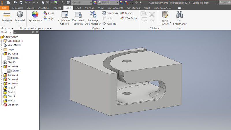
For this week's assignment and my new final project idea, I created two slightly differing cable holders for the cables of NeoPixel strip inside the temperature meter screen structure using Inventor.
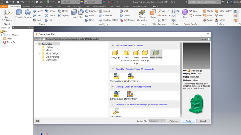
First of all, I opened the software and created a new file by navigating into the top bar and selecting File > New. Below Create 2D and 3D objects: select Standard.ipt and hit Create.
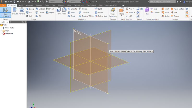
I changed the units to be millimeters by navigating into the top bar and selecting Tools > Document Settings. Next, I navigated into 3D Model > Start 2D Sketch > Start 2D Sketch which opened me XYZ-axes where I could chose the perspective I want to work with (I took XY-Plane). In this Sketch -mode, I started to design my cable holders using the tools in the top bar.
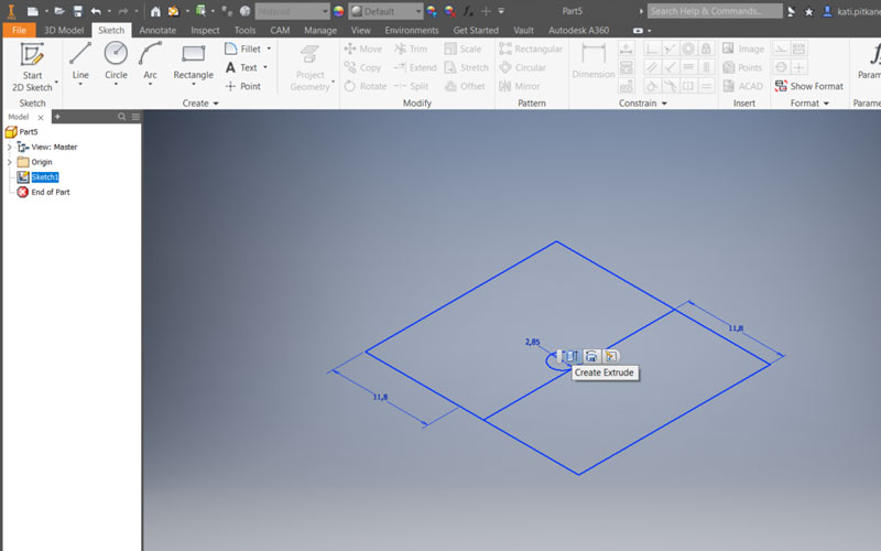
First, I defined the size of the cable holder (26,45 x 23,70 x 13,4 mm). I worked on this assignment afterward, so I had already desinged the screen structure and I utilized my Final Project to get the measurements and notice the details I had to take into account when desidning these holders, such as a hole for srewing the layers of the screen structure together and the NeoPixel strip cable going through and inside te cable holder.
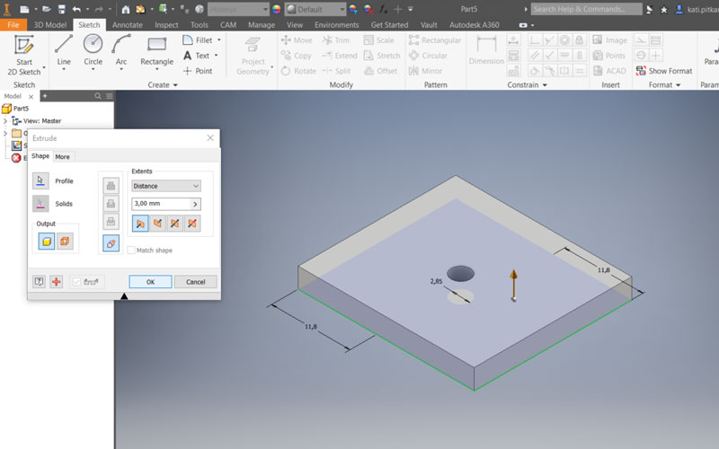
By navigting into a top bar and selecting Sketch > Create > Two Point Rectangle I created the outer edge rectangle of the cable holder. By using Sketch > Create > Center Point Circle I draw a circle in the middle of the rectangle. Then, From the top right corner of the tool bar, I ended this sketch by pressing Exit > Finish Sketch. Then, I extruded the part by right-clicking above it and pressing Create Extrude. In the opening menu I defined height (3 mm), direction (Direction1), and type of extrusion (Join) - is it a Join, Cut or Intersect.
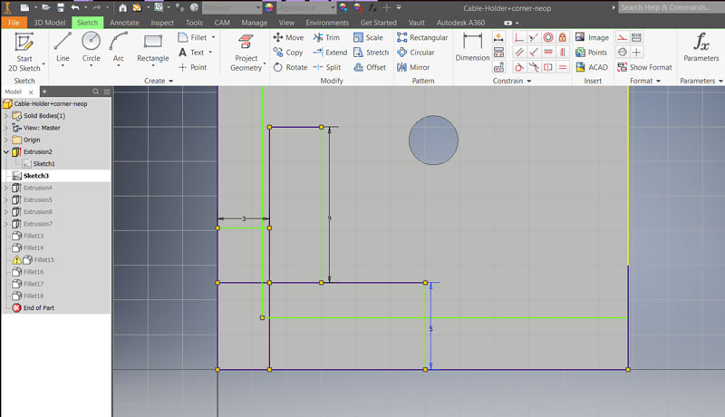
To place the circle correct, I draw a few extra rectangles with certain dimensions to indicate the correct distance from the outer edges. I have experienced that it is recommendable to do several layers/ sketched on the design, because it makes it easer to modify the design afterwards. So, further, I took a new Start 2D Sketch each time I had to draw something additional to the design, and after drawing each sketch I hit Finish Sketch.
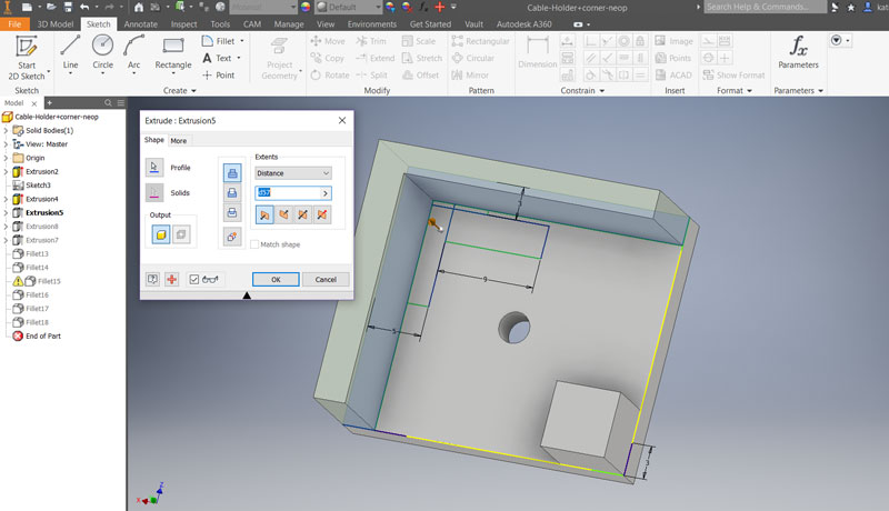
Taking into account the place of the hole for a data cable, and using same rectangle -tool, I draw the two longer walls and one small wall, and extruded them as follows: height 6 mm, direction Direction1, and type of extrusion Join.
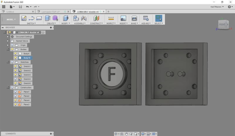
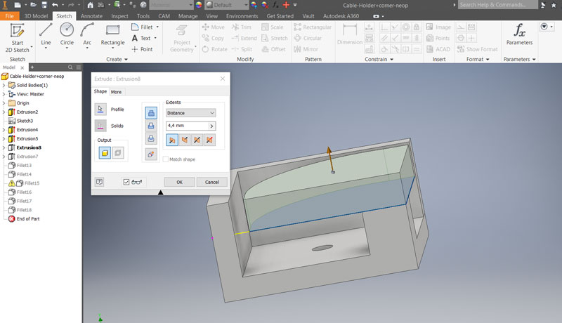
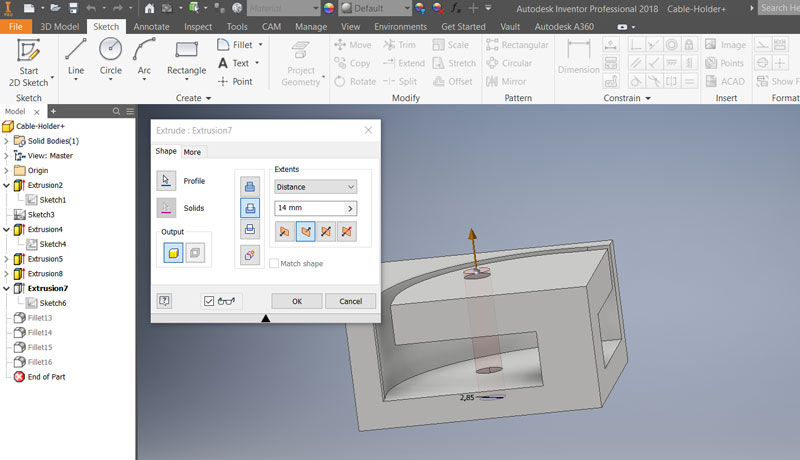
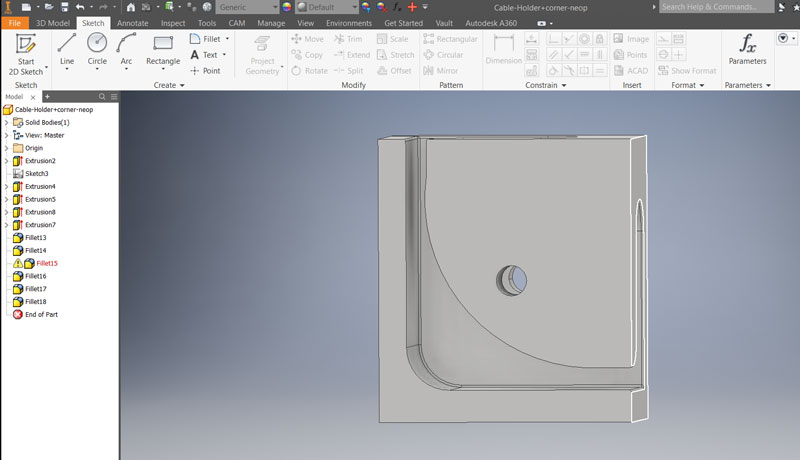
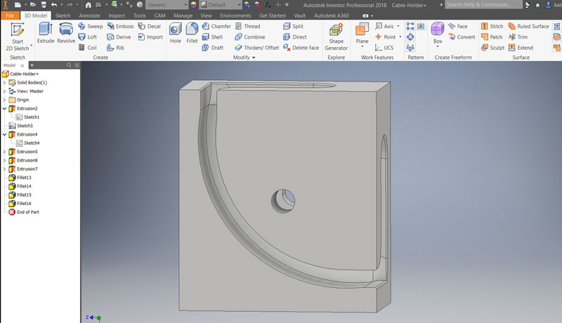
Then, combining and using Sketch > Create > Line and / Three Point Arc -tools to create the hat of the cable holder, and extruded it otherwise with the previous settings but height as: 4,4 mm (First picture, a cable holder number 1 intended for the corner of NeoPixe data cable). For extending the hole through the hat -part I created a new circle (because I did not manage to extrude the one in the very first sketch) and extruded it: height 14 mm, direction Direction2, and type of extrusion Cut (Second picture, a cable holder for the three other corners number 2-4 on the temperature screen structure).
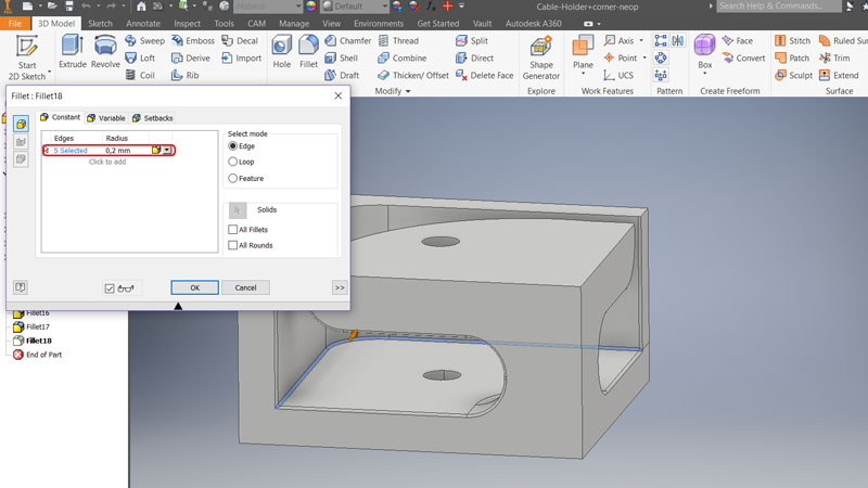
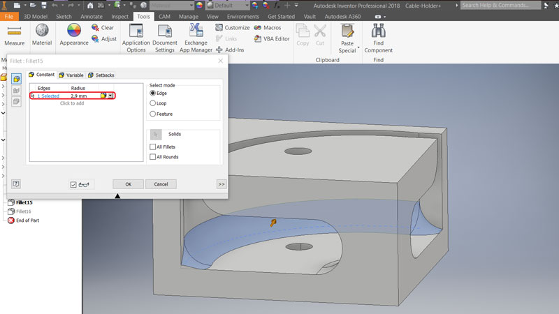
Using 3D Model > Modify > Fillet -tool, I selected some of the corners and added radius to the corners for making them rounded to avoid damaging the cables with sharp corners. The outer corners, which are not touching the cables, I left without radius.
Moreover, I added radius for making the thin strucure stronger, when there is no 90 degrees corners but some round and support on them.
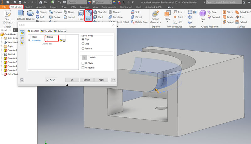
The first picture is presenting the corner radius of 0,2 mm in the bottom corner of the cable holder no: 1, nd the second is presenting the corner radius of 2,9 mm in the bottom corner of the cable holder no: 2-4.
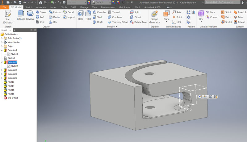
On the left is the finished model of the Cable Holder no: 1, and in the second is finished model of the Cable Holders no: 2-4. Finally, I saved the files as .ipt -format: File > Save As > Autodesk Inventor Parts (*ipt), and exported them both in File > Export > CAD Format > STL Files (*stl) and OBJ Files (*obj) -formats.
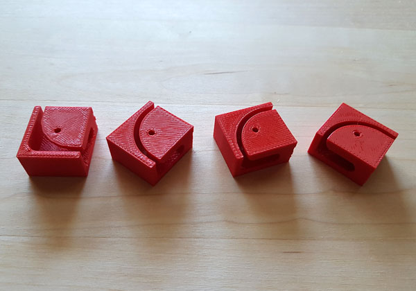
Later on, I printed the cable holders for my Final Project:
Here are the files of my Computer-Aided Design -Week including the Cable Holders for my Final Project:
- The 2D design of a rack for 3D scanner made with Inkscape in svg format
- The 2D design of a rack for 3D scanner made with Inkscape in dxf format
- The 3D modelling of the Heart Decoration made with Tinkercad in stl format
- The 3D modelling of the Heart Decoration made with Tinkercad in obj format
- The 3D design of the Cable Holder no:1 made with Autodesk Inventor in ipt format
- The 3D modelling of the Cable Holder no:1 made with Autodesk Inventor in stl format
- The 3D modelling of the Cable Holder no:1 made with Autodesk Inventor in obj format
- The 3D design of the Cable Holder no:2-4 made with Autodesk Inventor in ipt format
- The 3D modelling of the Cable Holder no:2-4 made with Autodesk Inventor in stl format
- The 3D modelling of the Cable Holder no:2-4 made with Autodesk Inventor in obj format