
Kati Pitkänen @ FAB LAB OULU · 2018
© 2018 Kati Pitkänen · Template by Bootstrapious

This work is licensed under a Creative Commons Attribution-NonCommercial-ShareAlike 4.0 International License.
3D Scanning and Printing
Week 6 · [ 21.02.2018 - ]
- Test the design rules for your printer(s) (Group Project)
- Design and 3D print an object (small, few cm) that could not be made subtractively (Individual Project)
- 3D scan an object (and optionally print it) (Individual Project)
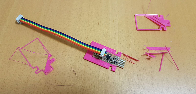
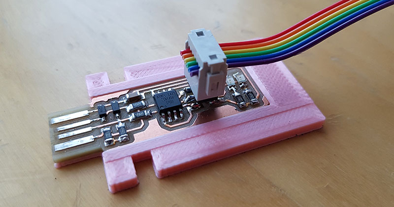
This week I 3D designed a plate and a cover case to my FabTinyISP programmer done last week. I familiarized myself with the advantages and disadvantages of 3D printing being additive manufacturing technique, when compared to traditional subtractive manufacturing technique done with e.g. a CNC machine. By the group work tests, we tested the design rules for 3D Printing on the three different 3D printers of the Fab Lab. Moreover, I experimented a scanning technology by several more or less successful trials to find the optimal settings for successful scanning.
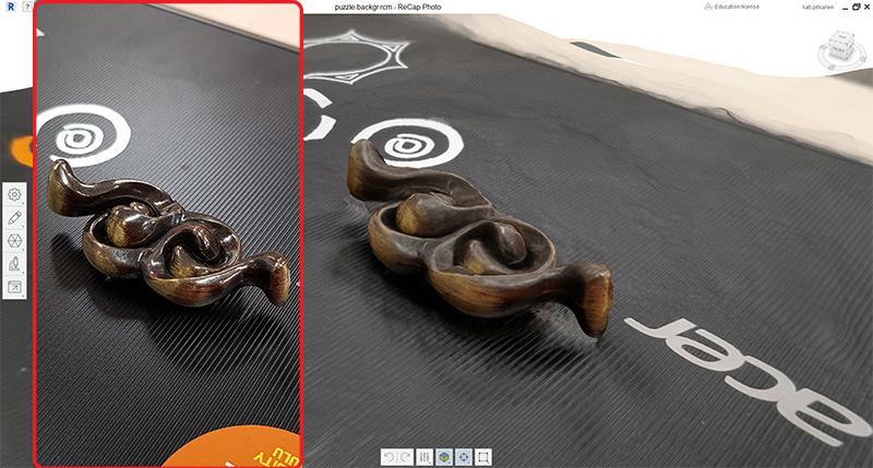
The object I chose for 3D scanning, a shiny brain puzzle, was not the best one for testing the scanning settings but made visible one of its challenges very well, where the shiny metal surface of the object reflected the environment and caused problems in photogrammetry results. The same rule seemed to apply to scanning environment and background, too. There has to be some reference points in the background and right under the object but it is a good idea to try to avoid materials reflecting light (and colors and extra stuff) to the surface of the object to be scanned. The other factor might be the light, which probably must be quite fixed.
However, it can be that I was too demanding for scanning results and I made a mistake when I expected to reach a "perfect" result. When I checked back my scannings afterward, there was some that were actually quite OK and guite easy to fix. So, now I am aware of the settings that I should prepare for making the scanning more succesfull and I think I could give this process another try some day.
3D designing in Inventor
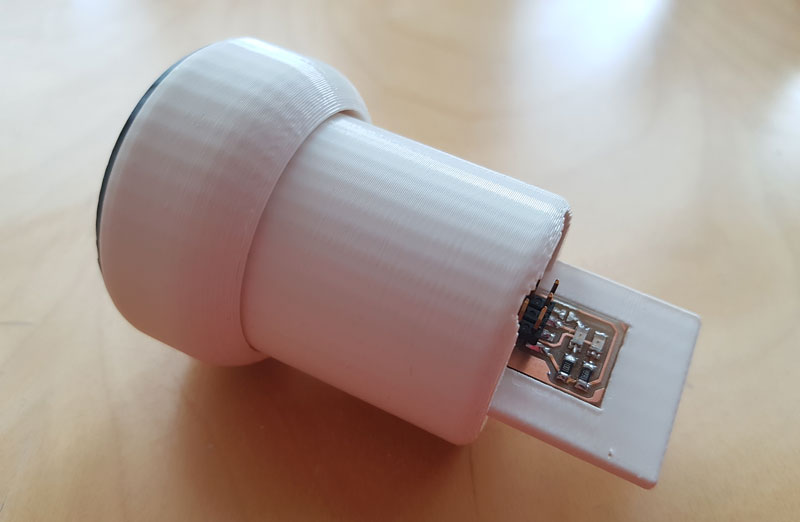
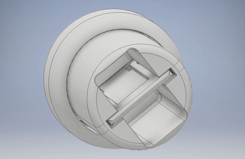
A Case cover for the USBTinyISP programmer I made last week 5. The case cover operates by rotating and locking the plate of the programmer inside the cover case to cover it and avoid it sliding out by mistake.
The cover consists of two rotatable parts which cannot be separated. Neither the cover could not be made subtractively, because it includes a movable part inside another solid part which could not be milled and manufactured traditionally; the milling bit could not have go on and reach the inner system of the lock and the latch even the orientation would have been fixed. Moreover, even the outer part of the design is fixable, using a traditional subractive method would have request that also the inner part of the design is attached on the working area, which is not possibe when considering the design and the characteristics of the two- or three axes machine. This is why I was able to manufacture this object only with additive manufacturing technique.
I used Autodesk Inventor for 3D designing as documented on the Week 3 - Computer-Aided Design. First of all, I took the measurements of the programmer by a caliper and designed the plate (bed) for the board. Then, I designed a case to cover it. I became quite massive since I wanted to make it in a circle form in order to try designing and printing a rotating lock, but I had to take into account the height of the 2x3 pin header as well as the cable above it.
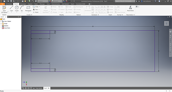
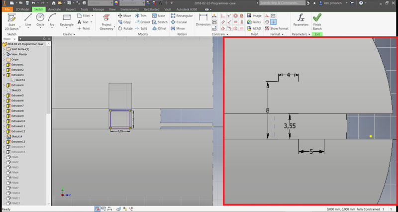
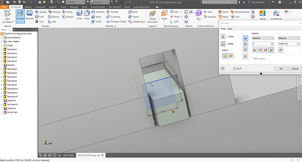
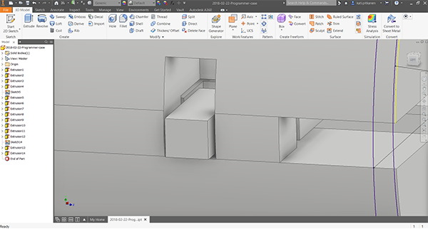
Using Sketch > Line, Arc, Circle, and Rectangle -tools, and 3D Model > Extrude -tool, I designed cuts to the plate, holes to the inner part of the body to reach the cuts, and latches of a lock keeping the plate still to the rotating outer part. The plate height is 2,8 mm and the hole it slides is 3,55 mm, so the space between the parts is 0,375 mm on each side.
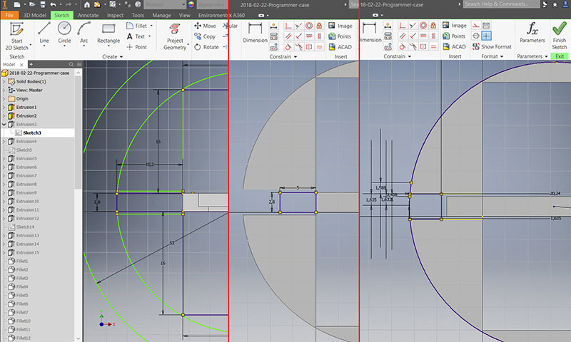
The latches are w: 3,35 x h: 3 mm and the holes are w: 4 x h: 8 mm. Also, the cuts in the plate are w: 4 mm. So, the horizontal space between the locking parts is 0,325 mm on each side.
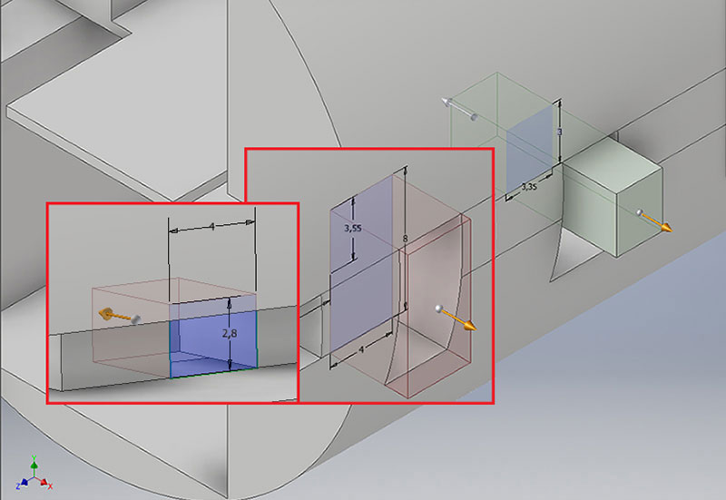
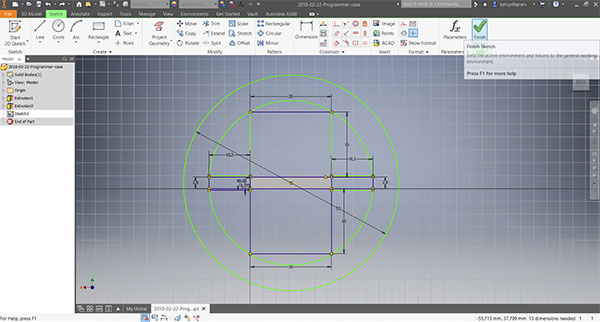
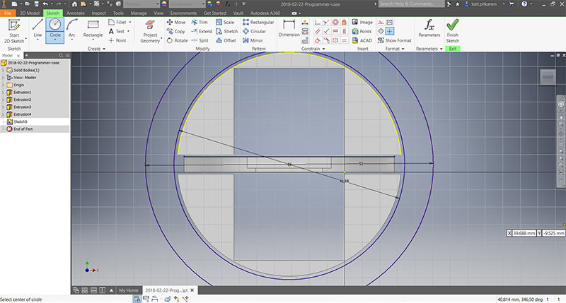
Designing the locking system and the latches of a lock.
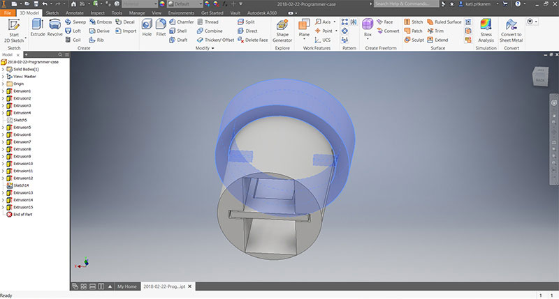
Placing of the latches of a lock.
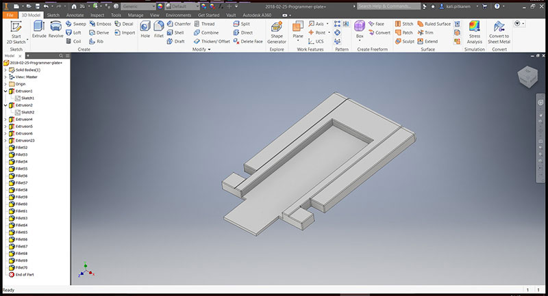
After the design was ready, I finished the visual appearance using 3D Model > Modify > Fillet -tool.
Re-designed plate having a slight border for the programmer.
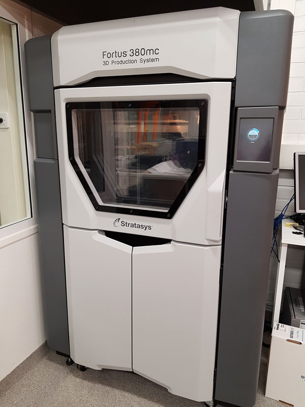
3D Printing: Stratasys Fortus 380mc
I printed the cover case with Stratasys Fortus 380mc and Formlabs Form 2.
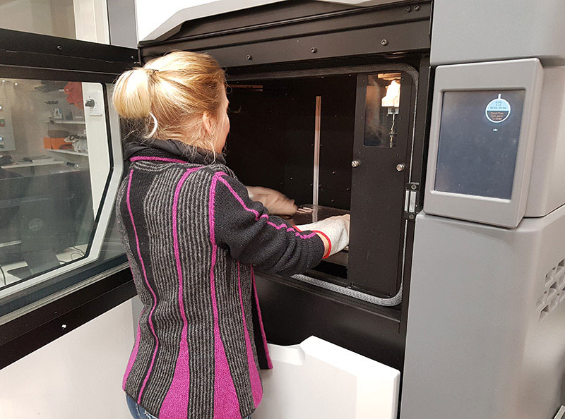
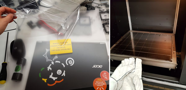
Check that the printer is ON. The oven is hot so by using the gloves, place a build sheet in the printer oven onto the platen. Make sure that the sheet is touching the metal pieces on the back side and the left side of the building area, and close the door. The user interface is comprised of a touchscreen. At this point, when checking the UI, the 'State' of the printer is orange and there is the red cross over the 'Vacuum Status Indicator'. After the oven has heated up the sheet around 5 minutes it becomes more smooth and it is possible to verify vacuum to secure the build sheet to the platen. Once the sufficient vacuum is achieved, the red cross over the 'Vacuum Status Indicator' disappears, the state of the printer becomes green, and the printer is prepared for printing.
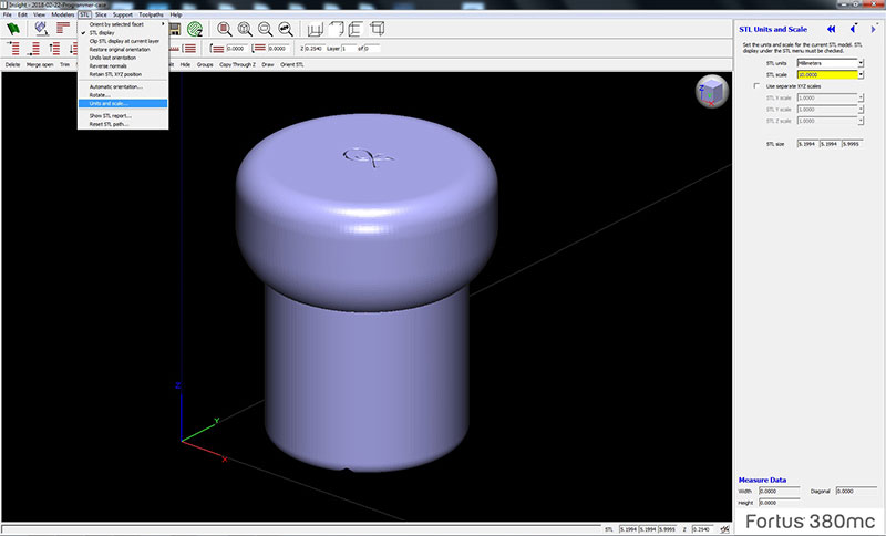
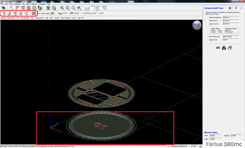
Open the Insight software for doing the print settings, and open the .stl file. Since I had done the file in Inventor but had not taken into account the difference in unit settings between Inventor and Insight, I had to scale the object in Insight by navigating in the top bar STL > Units and Scale. For the future, I changed the settings in Inventor so next time, I don't have to do it.
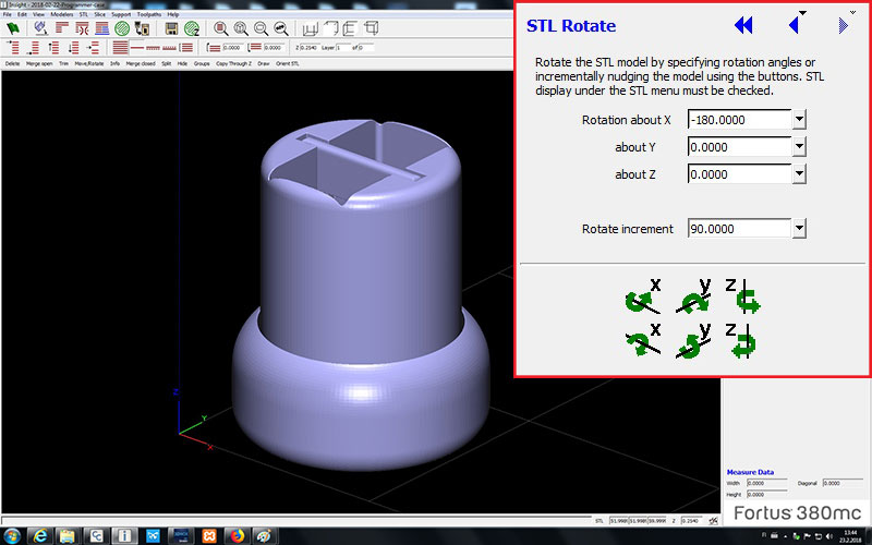
Rotate the object to be printed in appropriate orientation so, that the layers rest on each other as much as possible and there is a need for support material as less as possible.
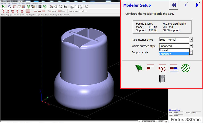
Setup model preferences:
- I selected Part interior style to be Solid - normal' because I thought that the cover has to be firm enough to protect the programmer in many settings. 'Sparse' would have printed the part faster but made the object lighter, where 'Sparse - double' is between the two other options.
- In order to get more smooth surface, Visible surface style needs to change from 'Normal' to Enhanced.
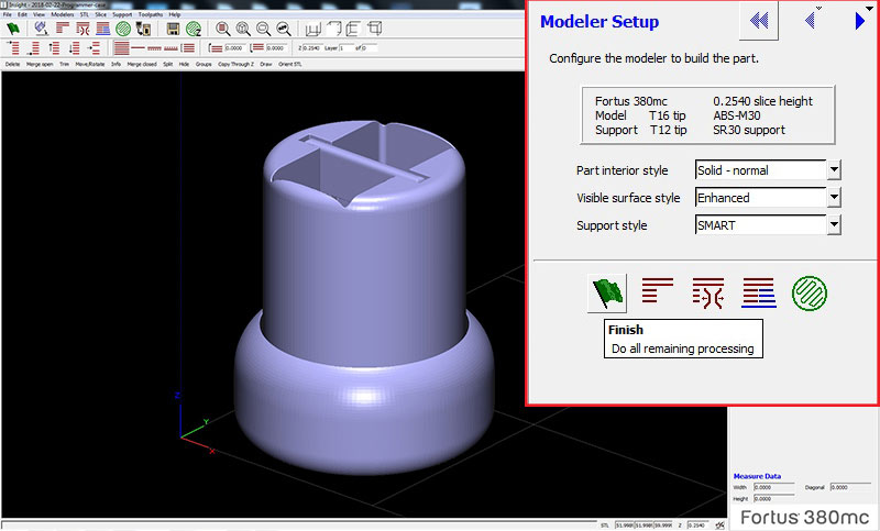
Then, select the Green Flag - 'Finish' which creates the slices.
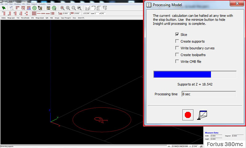
By navigating in the top bar it is possible to move between the layers to check how are they going to be printed.
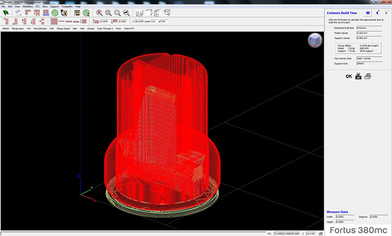
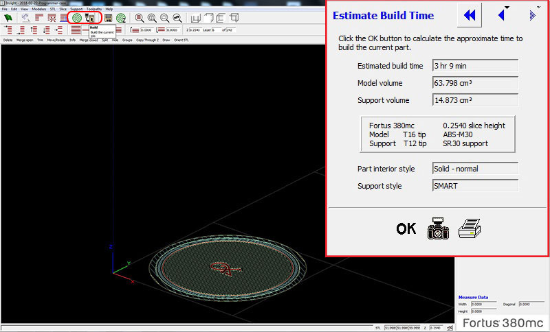
Next, by navigating in the top bar, Generate Toolpaths for the part. (In order to play with very precise parts, you can modify 'Contour width', and 'Wall Thickness'.) Now, the estimated build time is given (3 hours 9 minutes). In the top bar the, select Build.
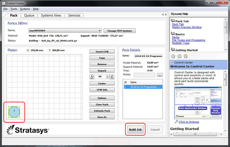
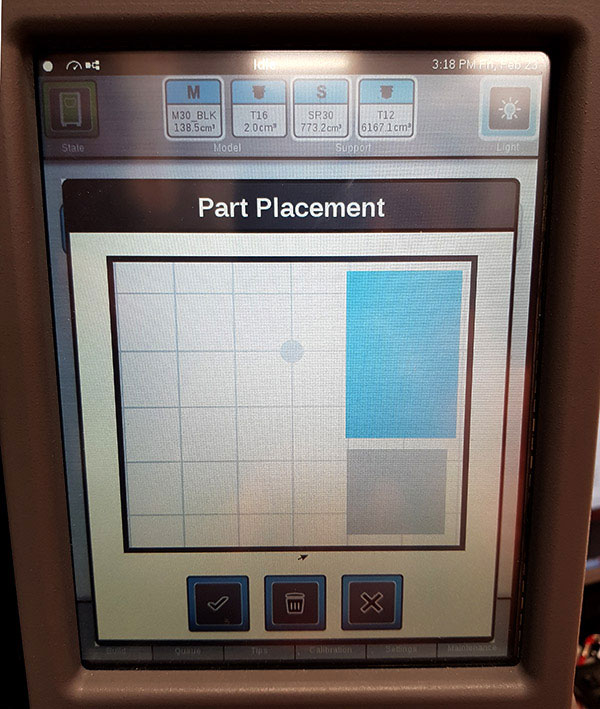
Control Center -window will appear. Place the object appropriate and select Build Job.
In the printer's UI, I can see the file I have sent for printing (or find it from the queue). The screen tells me the Material Status - how much filament there are available in the canister, and how much is required for this printing, as well as the Build Status - printing time and when will the print be finished. (In the picture printing time is different from the estimated time since it included several prints.)
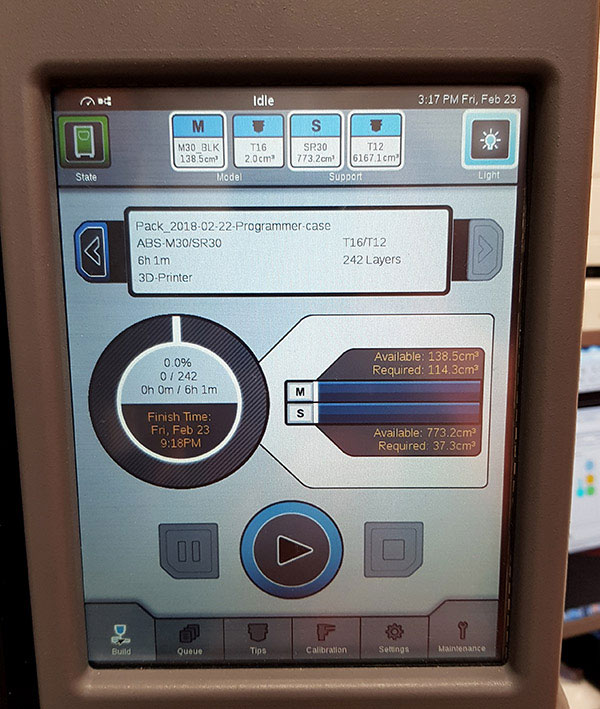
By using the touchscreen I placed the object to clean place on the build sheet, pressed GO, and started the printing.
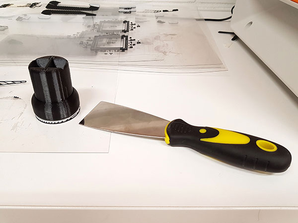
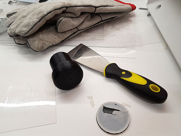
By using the gloves, remove the build sheet from the oven, and use the spatula for removing the object from the sheet. Then, remove all the support material that is possible to take away by hand.
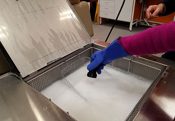
Check that the temperature of the lye (sodium hydroxide, NaOH) tank is around 55 oC, and that the pump is on. The amount of the liquid was too less so we added warm water to the tank first. Then, I added my object to be soaked in the lye tank. When placing check orientation so, that the object will be fulfilled with the lye. Remember to wash the gloves.
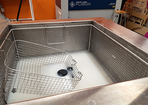
The results of soaking after 6 hours and after 27 hours can be seen from these pictures:
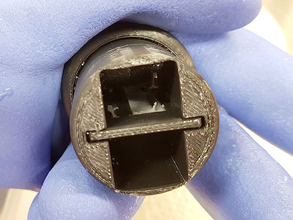
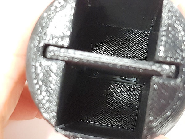
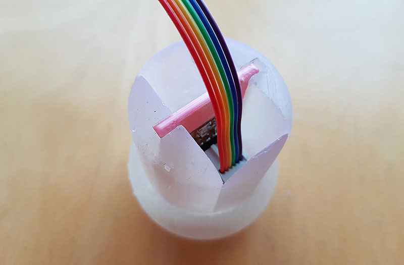
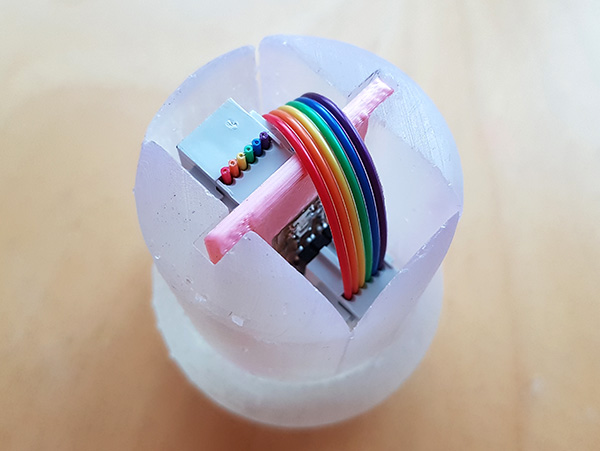
Pictures below are presenting, how the latches of the lock are attached to the wider and outer part of the cover, and the holes they are sliding in are located on the inner part of the cover case. I had one small but critical mistake on my first design in one of the two latches of the lock. For some reason, instead of 3 mm latch height, the latch was 4 mm height, and when I was trying to remove the programmer plate it was stuck, because the latch was too high and prevented the plate to slide off.
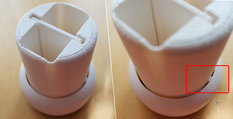
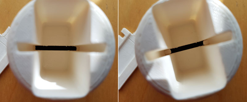
I fixed the design (decreased the height of the latch to 3 mm) and printed new version of the programmer cover case, which works fine. Another option (and maybe even better) would have been to increase the height of the slot when the rotation movement would have been greater as well. However, the filament run out during the printing and I asked, if we could make the print two-colored, which we did.
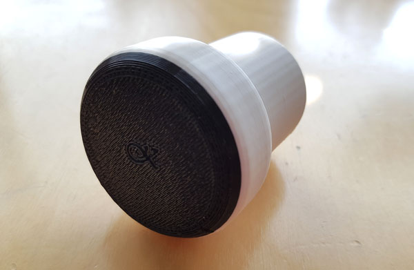
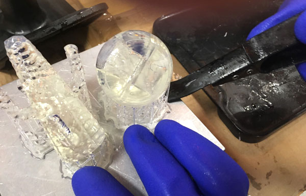
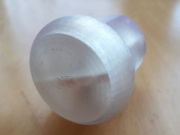
Here is the final result of my 3D designed and printed object that could not be made subtractively:
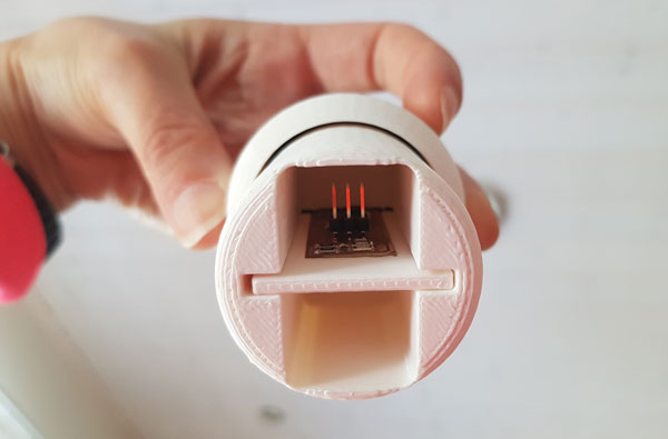
The plate is safe and will not slide off even the cover case is upside down:
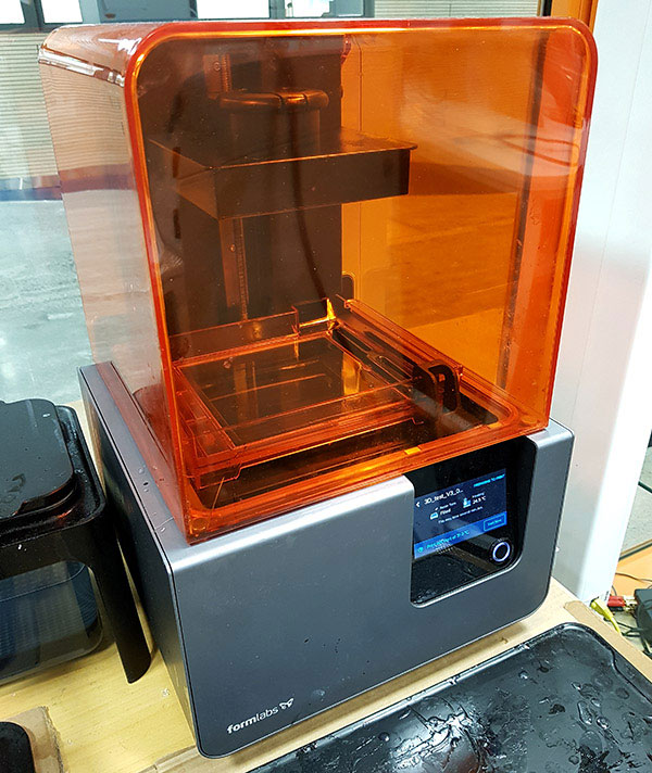
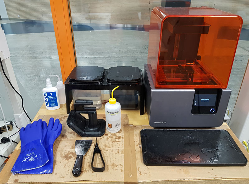
3D Printing: Formlabs Form 2
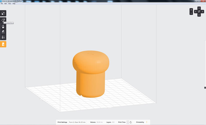
Formlabs Form 2 is a printer, which uses resin for printing and creates support that has to be removed manually. This is why I decided to print only the cover of the programmer without the plate inside of it. I was curious to see, would it be possible to make the cover look shiny as a lens and be able to see the plate and the programmer through it.
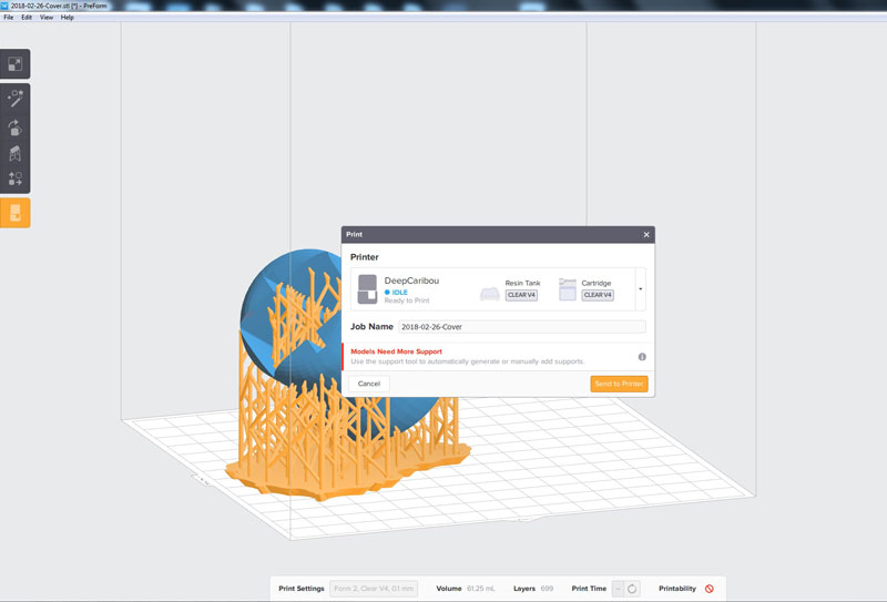
Open the PreForm software for doing the print settings, and open the .stl file. For quick calculation, I selected Magic which adjusts the orientation of the print and adds support for printing.
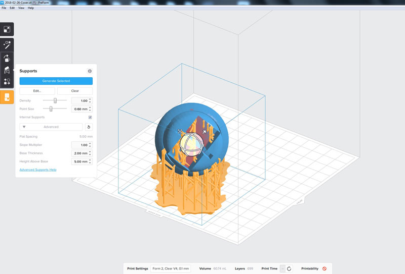
The default settings seemed to create a huge amount of supports inside the cover but I reduced the amount because I was afraid that it would be too hard to remove it. Printability almost touched the limits but I found the settings that were acceptable.
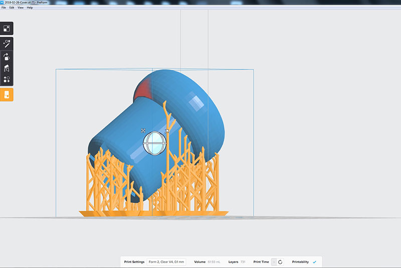
Estimated printing time was calculated by pressing Printing Time in the bottom bar. Then, I pressed Print and the printing data was sent to the printer.
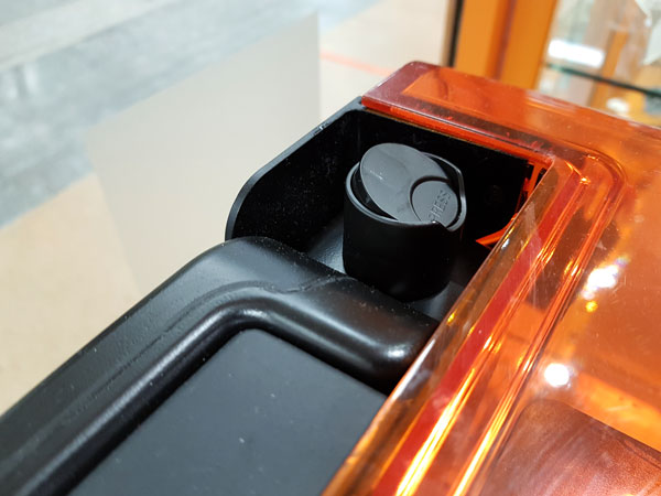
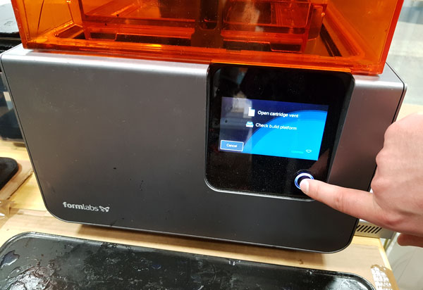
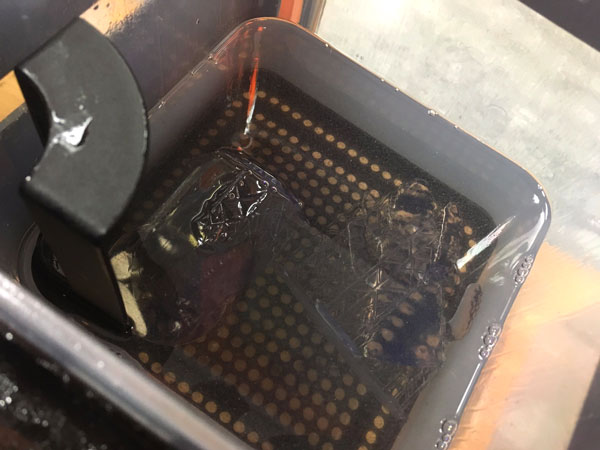
When starting to print, check carefully the name of the print and press Print Now. As the printer instructs, open the cartridge vent on the top of the machine, check that the build platform is set correctly, and Confirm it. Now, the printer starts heating and printing the file. During printing, the print is composed dipping it down in the resin layer by layer, and hardening the resin liquid by exposing it to the ultraviolet light. The object will be printed as it hangs from the building platform. At first, the printer creates a layer attached to the building platform where the printable object will be stuck.
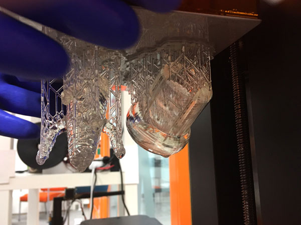
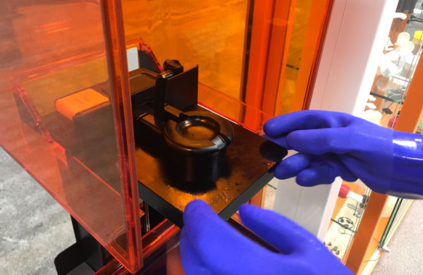
Always wear gloves to remove the print from the printer and to do the finishing and cleaning phase. First, open the orange cover of the printing area and take the building platform out from the machine. Remove the object from the building platform carefully with a small plastic spatula.
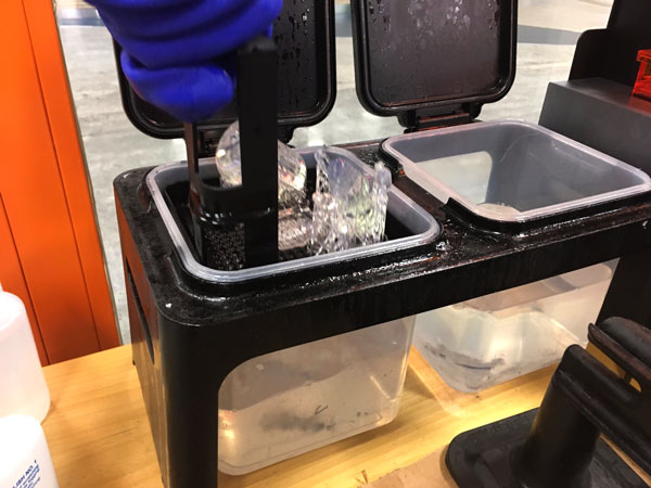
Next, after printing the print needs to be dissolved in the two boxes filled with alcohol. First:
- Soak the print in the left box by moving the basket inside of it up and down in the liquid for 30 seconds and then,
- Leave the print to stay in the liquid for 10 minutes.
After that,
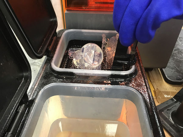
- Move the print from the left box to the right box to be soaked for another 10 minutes.
Meanwhile, clean the building platform and spatula with Isopropanol and paper. Put the building platform back to the printer.
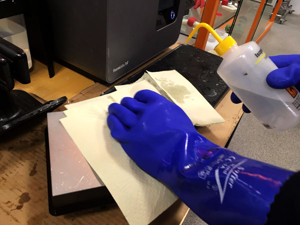
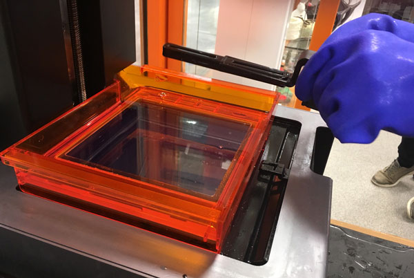
Also, clean the resin tank.
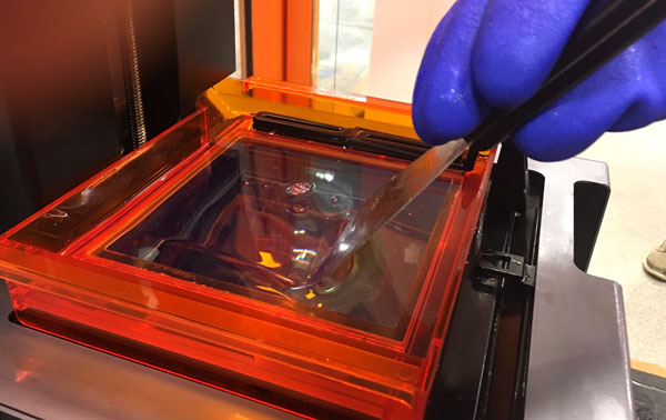
- Take the bar cleaning the tank during the printing and carefully pull and slide it to place it on the edge of the tank.
- For cleaning the bottom surface of the resin tank, use a spatula in the 45 degrees angle and slide it carefully moving only one direction (forward).
- Slide the bar back to its original place.
Close the orange cover, and close the cartridge vent on top of the printer.
After soaking the print in the second box, take the print out of it, wash it in the water and dry it. Cut the support right from the surface of the print using tiny side-cutting pliers. Sand the surface of the print. I still need to finish the print and polish the surface to make the material of the cover case look shiny.
Unfortunately, I added too much fillet on the edges in the design, which left a cover case with too thin corners breaking easily. Also, I learned that polishing the surface takes very much effort. Considering that, the object or the walls of this type of object must be strong to not break during polishing.
Print Setup I used in Cura, since I wanted to try printing the plate with my WANHAO Duplicator i3. I set the parameters for layer height, wall thickness, infill density, and decided to not build any support.
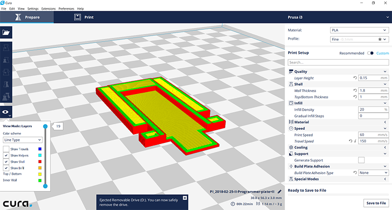
The first two prints failed and the material ripped away layer by layer. Maybe, since the filament has been open for a while, it has got moisture a bit. Could be, that increasing the heat would help. After changing the filament, the print succeed.
Using additive manufacturing technique that 3D printing is has its advantages: when compared to traditional subtractive methods, there is no limitations regarding the orientation of a tool - user does not need to take into account in which orientation a milling bit can go or if it can reach some certain point or not. Instead, 3D printing starts constructing an object successively depositing material layer by layer such that it becomes a designed shape. Support material takes care of the parts that would otherwise hang in the air in printing phase. Moreover, when fabricating an movable object inside an object, there is no consideration how to attach the inner part for milling. Neither there is need for changing the tool for manufacturing different phases or precision on the 3D object.
What comes to the disadvantages or limitations of 3D printing, the precision of the printing quality is not yet that accurate when compared to traditional subtractive manufacturing, such as CNC manufacturing, by which 3D objects are constructed by successively cutting material away from a solid block of material.
After this week's tests and trying out the three 3D printers of the Fab Lab, I still count the most on the big Stratasys Fortus 380mc printer. I think, at least for most of my purposes, the quality is very good. Moreover, using the machine is simple and the support that can be soaked away works quite nice in many cases - especially if I want to make something that cannot be made subtractively, and if the design is not too closed but there is holes enough to let the lye go in and out to soak the support away.
If I would like to have very precise result, I would turn on Formlabs Form 2, which has the best printing quality. However, operating the machine takes a little bit more time and effort, as well as the printing time in very precise parts is quite long. What comes to Shindoh 3DWOX, to begin with, it didn't convince me at all because we had a lot of challenges to get even the test part printed. Afterward I have noticed, that when it works, the results are actually quite nice, though.
About the challenges, and ensuring the success in 3D printing, in any of the printers it is important to take care of and check the condition of a printing plate/ building area every time, or otherwise the filament (or resin) won't stick on the surface and printing the object may not get further.
3D Scanning / Photogrammetry
I tried taking pictures for photogrammetry by several ways:
- two cameras
- i) mobile phone camera and
- ii) system camera, and
- two different approaches
- iii) rotating the plate when only a small area of the background changes vs.
- iv) moving the camera around the object when a big area of the background changes.
In the first trial, I scanned the object by using a mobile phone camera and rotating the plate covered with some recognizable background.
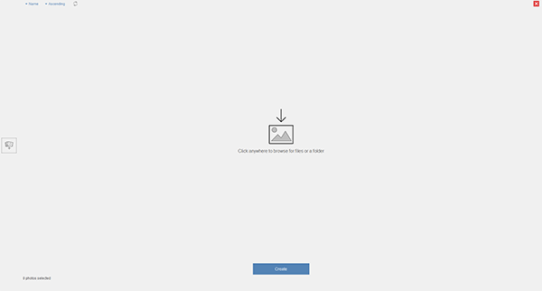
Then, I installed Autodesk ReCap Photo.
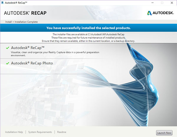
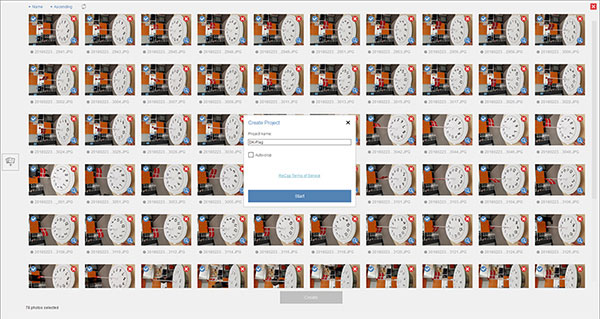
I selected pictures and hit 'Create'.
Naming the project.
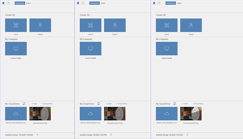
Autodesk ReCap Photo uploading, registering and processing. Unfortunately, creating the model failed.
I tried also another, bigger object using system camera and by rotating the plate but again, Recap Photo failed to create a model and I realized, that the background needs to change to give reference points for photogrammetry calculation.
For next trial, I changed the background to be more detailed, used system camera, and moved the camera around the object - and got the first result!
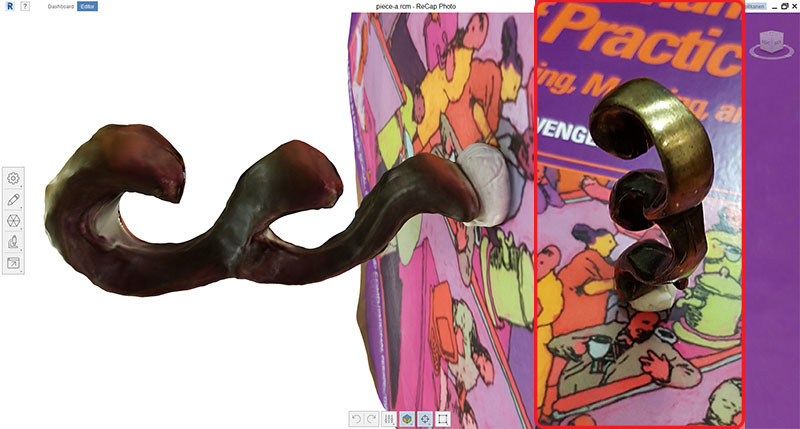
The result was a bit blurry and I couldn't see all of the corners yet so, I tried to change the background, and used mobile phone camera around the object. This was the best result so far, and Antti tempted me to try out if I could scan the two parts of this brain puzzle separately and try to catch each corner of them, and print them successfully, and for sure I wanted to try it.
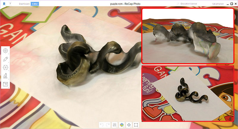
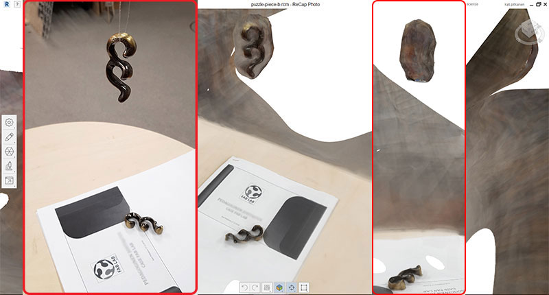
At this point, I didn't see any difference of taking pictures with system camera or mobile phone camera so I continued only with the latter one. For trying to catch each corner of the object, I dangled it in the air near the table with some reference points, and moved the camera around the object. The result was that part of the object was somehow ok as seen in the picture, but part of it (backside) failed totally. I think that the reference point has to be closer to the object than it was in this setting. Also, since the object is quite small, it might work better when taking the photos nearer.
I made several trials after these and found varying background with some reference points to be the best for scanning. However, most of the results were good from the one side but failed from the other side, and I think that problem was caused by the varying light around the object.
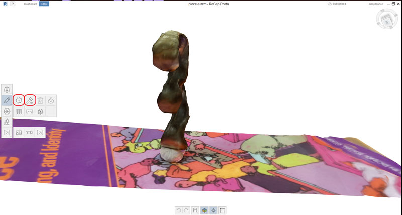
Placing an object upright position, I tried scanning it again on the table and close to the object ths time. I changed the background to be more detailed, and moved the camera around the object, and got the better result. Autodesk ReCap Photo uploaded, registered and processed me 65 pictures creating following model:
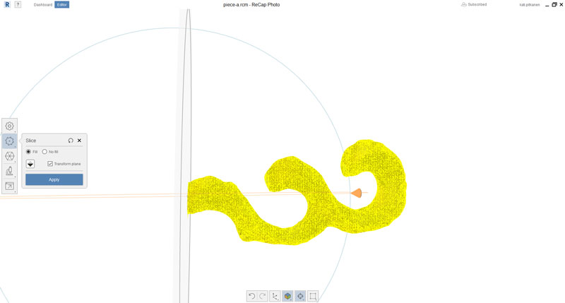
I accepted this result for further processing. I edited the scanned 3D model in ReCap Photo using the tools Edit > Slice and fill and Edit > Surface -tools.
I was able to remove all the extra parts using Edit > Slice and fill -tool and rotating the axes in different positions.
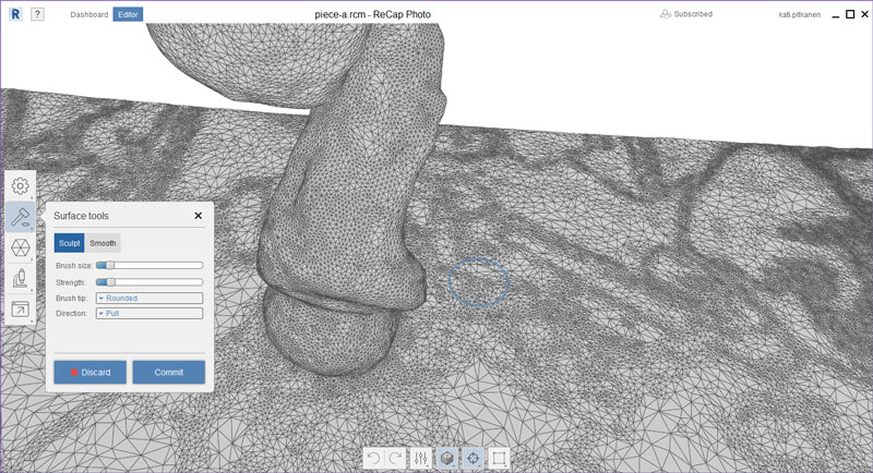
Fortunately, I did not have even a single hole in my model. The shiny surface was a bit winding, which I tried to pull and push using Edit > Surface -tool.
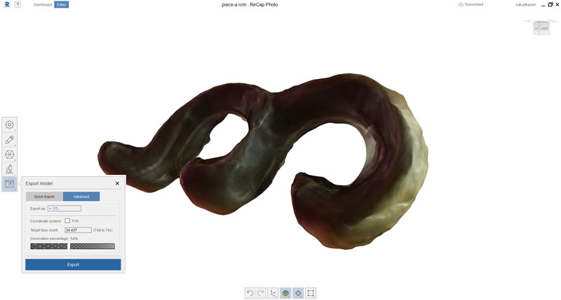
Here is the finished 3D model. I had to admit that the object I chose was not the best one for testing the scanning settings. It was quite challenging to picture an shiny object as this one because it reflects and mirrors the environment around it. However, I was happy to get this results after all my efforts.
I reduced the size of the model and exported it both in stl and obj format.
Managing the 3D Printers
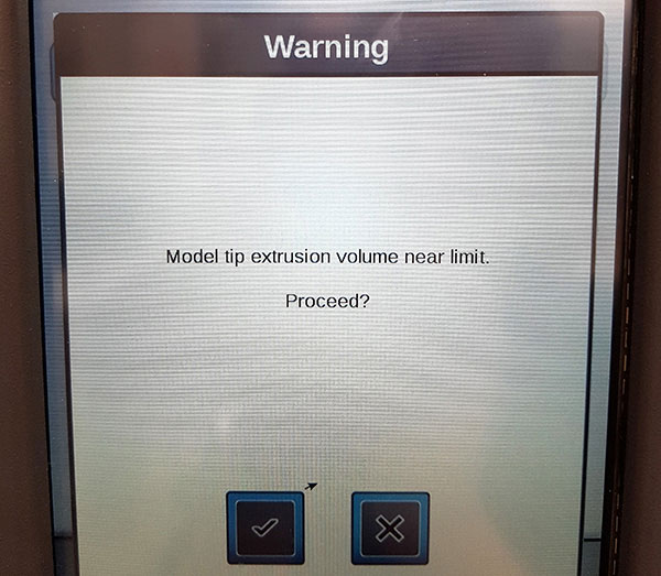
When sending the file to the Stratasys printer it informed that the printer’s model tip is near its odometer limit so, I got a great possibility to learn the process of switching the ABS-M30 model (T16 tip). I followed the directions of our local instructor Antti Mäntyniemi and the Stratasys User Guide.
By using the user interface touchscreen, I navigated to Tip Change(Wizard) by the Tips button.
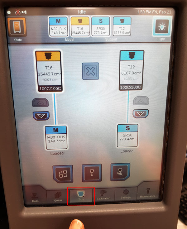
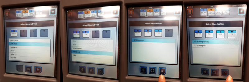
- Select the model material to be switched: ABS-M30.
- Select the model tip to be switched: T16 (current) to T16 (new) and press 'Next'.
- If there is no need to change SR30 support material or tip, leave current and press 'Next'.
- Ensure, that there are no parts on the platen. Confirm by pressing 'Next'.
Now, the printer prepares for Oven Cleaning, moves platen to oven cleaning location, and unloads the current material ABS-M30 from the liquefier, which takes around 5 minutes.
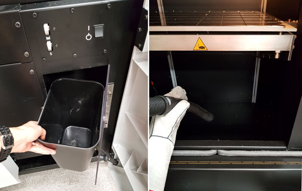
- While waiting, empty the purge bucket under the oven.
- After the preparing for Oven Cleaning is finished, vacuum clean the oven carefully (see and be careful with the sensor inside the oven).
- Close the hood and the door and press 'Next'.
Once the material unload is completed, remove the unloaded canister and then press the 'Next'. For removing a partially used canister:
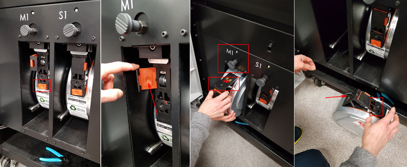
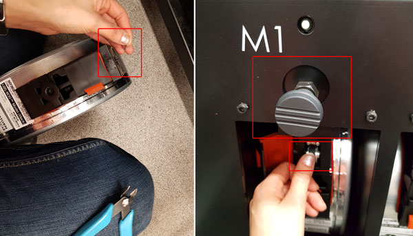
- Open the canister thumbwheel door, re-insert the square foam gasket from its storage position into the thumbwheel door to prevent the thumbwheel from moving, and close the door.
- Raise the canister drive off the canister by lifting the grey Canister Release Knob (M1).
Immediately pull the M1 canister out of the bay (within 10 seconds of lifting the canister release knob in order to avoid drive motors to pull the material from the printer to the canister). - Cut the filament flush with the top of the canister snout by cutters.
- Remove the plastic plug from its storage location and insert it to the operating location into the filament outlet hole of the canister snout.
- Now, the printer clears the filament remaining within the filament tubes. Pull remaining filament from the canister drive.
Confirm the material tip change and the tip head will move to the service location.
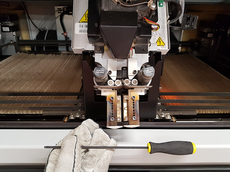
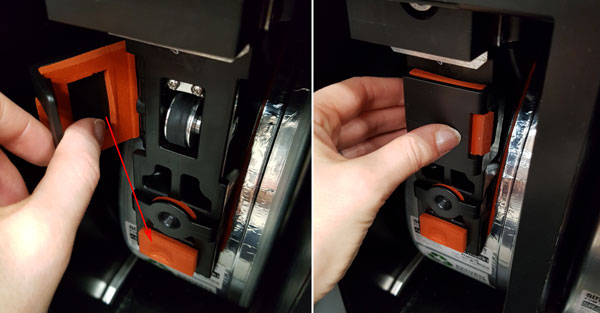
I continued by opening the hood of the printer, and removed the head and placed it in the service bracket:
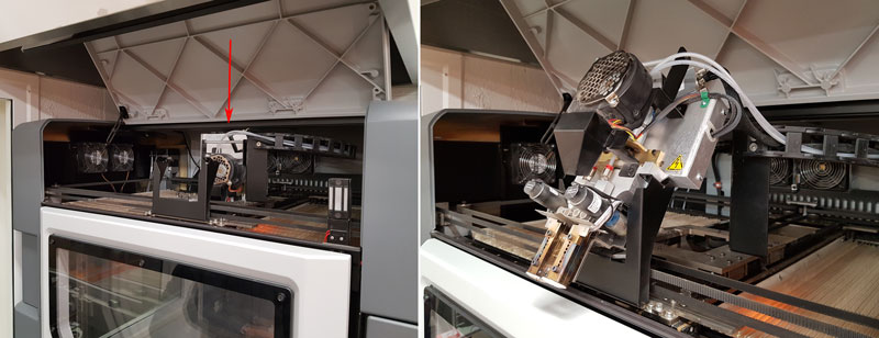
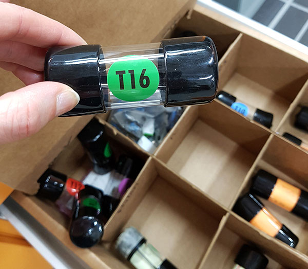
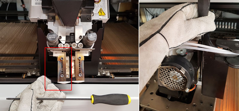
Then, I removed the old tip, insert the new tip, replaced the head to its position, and closed the hood:
In case I would have change for the previously used tip, I would have marked down the tip odometers (from 'Replace Tips' phase), and update the tip's odometer information to reflect the previous usage. This time I was inserting a brand new (unused) tip so no configuration was necessary, and I could just accept the default values and hit 'Next', and the material change will be saved.
Next, I prepared for tip calibration.
- There was no build sheet clean enough so I took a brand new build sheet, and removed the cover plastic,
- Installed the sheet to the oven onto the platen, and
- Waited for the printer to verify vacuum to secure the build sheet to the platen.
Then, I
- Cut the filament to be out of the canister around 1 cm, and
- Pushed and installed the canister back into the canister bay by pulling out the grey 'Canister Release Knob (M1)'.
In few seconds the printer red the canister's memory chip and showed canister's information displayed within the 'Material Status Icon' on the screen.
To pre-load filament to the drive wheels, I opened the thumbwheel door
- I removed the foam gasket square inside the thumbwheel door and stuck it onto canister's side back to its storage position.
- Then, I fed filament into the drive mechanism by pressing in and down on the thumbwheel and turning the thumbwheel until I felt the canister driver motor pulling the filament. Now, the filament was ready to be loaded to the liquefier tips in the head.
Finally,
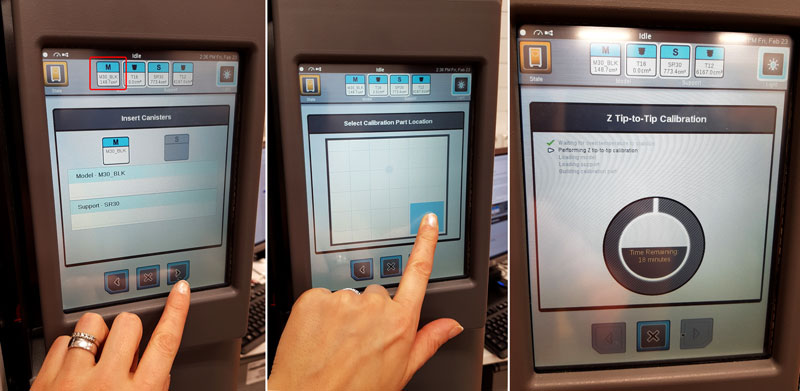
- I selected the model canister to be loaded during the calibration sequence by pressing the corresponding row, and hit 'Next'.
- Then I selected the location on the building sheet to start the calibration part's build and hit 'Next'.
- Now, the printer began the process of building a calibration part, which took around 18 minutes.
Once the calibration part was completed, by using gloves, I removed it from the printer and hit 'Next'. The Adjust XYZ Calibration page was opened.
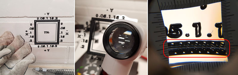
- I analyzed the calibration print by using a magnifier and viewing the relationship between the support calibration toolpath and the alignment indicators to determine the X and Y axis calibration.
- For that, I held the build sheet up to the light to view the toolpath and determined on which point of the line on each axis the white support material toolpath is most centered between the black X-Y alignment indicators.
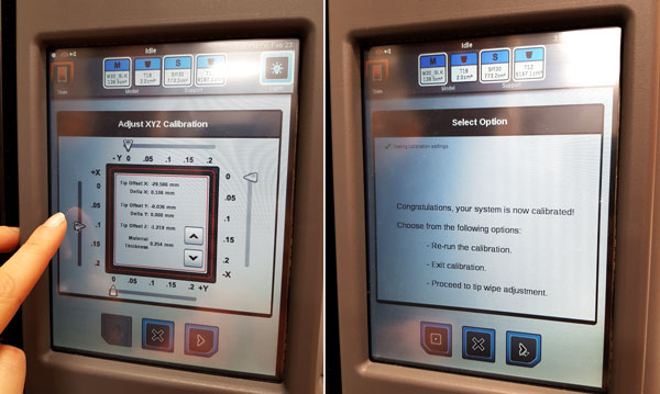
I made the needed XYZ tip offset adjustments based on the analysis within the Adjust XYZ Calibration page. In there:
- I slid the scale icon on the screen to match where the support toolpath was most centered between the alignment indicators.
- The only scale I had to adjust was +X which was the most centered in the alignment indicator phase .1 (mm).
- In case the adjustment value for either axis is required the calibration part needs to be rebuilt.
- Once the calibration toolpath for X and Y was adjusted, I proceeded to the Z offset adjustment.
As a final step, the Z Offset Adjustment was determined.
- The support layer from the inner square of the calibration part was peeled off.
- The thickness of the support layer was measured with a caliper in the center of each side of the square.
- If the value is within ±0.01 mm of the model tip’s slice height the printer is calibrated for the Z axis and an adjustment is not required. If the value is not within ±0.01 mm, the average value of the four measurements has to be entered for the Z offset adjustment using the 'Up' and 'Down' buttons.
Once the calibration adjustments were done, I hit 'Next' and they were saved. Furthermore, I hit 'Checkmark' button.
The tip extrusion is recommended to be completed by adjusting tip wipe height. The tip wipe assembly contains two brush assemblies which are used to keep tips and tip shields free of purged material debris and buildup, where the flicker cleans the tip’s opening, while the brush cleans the tip shield.
- Open the canister bay doors
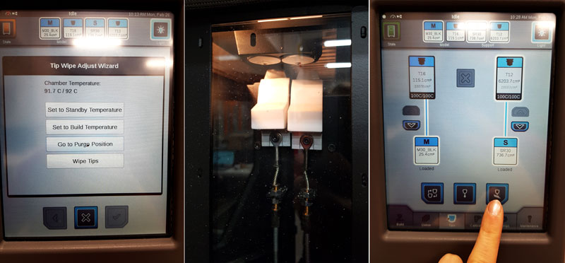
- In the Tips page, press the Tip Wipe Adjustment button.
- Press the Go to Purge Position button which will move the head to the purge position
- Press the Wipe Tips button, when the head will begin to move back and forth making four passes where the head gradually moves horizontally across the flicker to ensure proper adjustment and even wear.
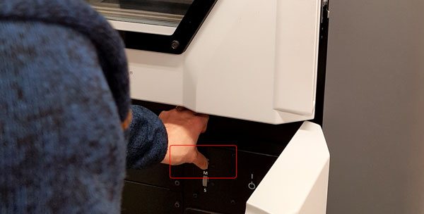
- Observe placement and if needed, use the Tip Wipe Height Adjustment Wheels to adjust proper tip wipe height.
- The 'User Guide' instructs that:
- "The tip’s opening should slightly graze the top edge of the flicker. The flicker should not have any contact with the tip shield.
- If placement is too high, extreme resistance will occur when the tip passes over the flicker, which may cause damage to the flicker/brush assembly."
After the adjustment is finished, close the canister bay doors, and the tip extrusion process is completed.
Here is the ZIP-package containing the design and scanning files of the week:
- The cover case for The FabTinyISP board in ipt format
- The cover case for FabTinyISP in stl and obj format
- The 3D model of The Brain Puzzle Piece scanned by photogrammetry in stl and obj format.