Computer-Controlled Cutting
Week 4 · [ 7.2.2018 - ]
- Characterize your lasercutter, making lasercutter test part(s), making test part(s) that vary cutting settings and dimensions (Group Project)
- Cut something on the lasercutter. Design, make, and document a parametric press-fit construction kit, accounting for the lasercutter kerf, which can be assembled in multiple ways (Individual Project)
- There is no specific project that is focussed on this very useful tool. There are a range of ways you might utilise it throughout the programme, or your local instructor may set a specific project. You might make: Stickers, flexible circuit boards, a textured surface/relief pattern, screenprint resists/stencils (Individual Project))
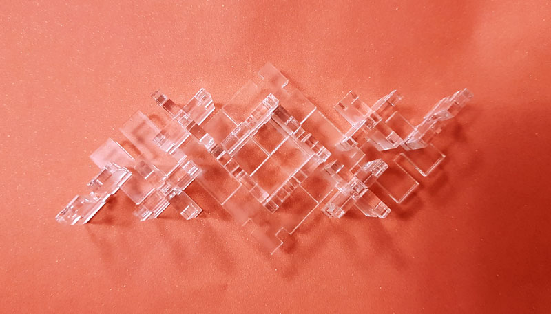
I didn't manage to create my first design, the puzzle cube file as a parametrical model design during the week but however, through the example piece I created I found the parametrical drawing very interesting and useful in order to modify the design easily to be cut in many sizes, and fit for different materials as well as for varying material thickness.
Both laser cutter and vinyl cutter were previously familiar to me, but before this week I had never took kerf into account accurately. After cutting the example piece I created with both normal design as well as parametrical design the difference was obvious, where the pieces of my parametrical press-fit construction design fit together precisely without being loose and sliding away.
I had not use Adobe Illustrator for designing a sticker so, it was nice to try it out, as well as revise operating with the vinyl cutter and think about new possibilities to use this great machine which I tend to use too less with respect to its possibilities.
Laser Cutting
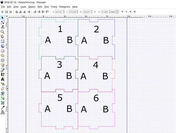
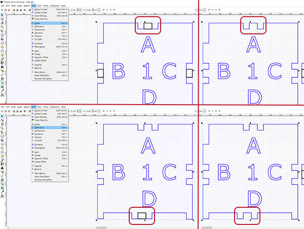
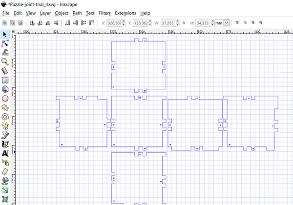
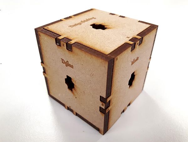
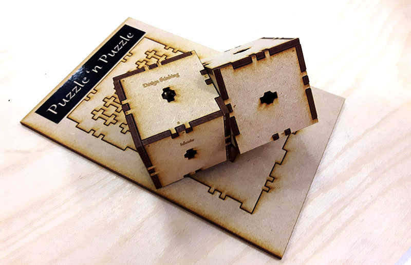
I wanted to make a puzzle cube, which is a sort of tabbed box. First of all, I had to draw a quick prototype of it to figure out differentially placed connectors fitting to each other. I had to find out how are the six pieces of 3D cube's sides connected to each other in a 2D model.
At first, I designed a model having wider slots but I prefer connector slots to be squares so I made them smaller to fit e.g. with MDF 3 mm material. For connecting several cubes, I designed a rotatable connector.
In order to cut, line width has to be 0,02 mm, the .svg -file needs to be saved as .pdf and the 'Resolution for raserization (dpi)' must be at least 300.
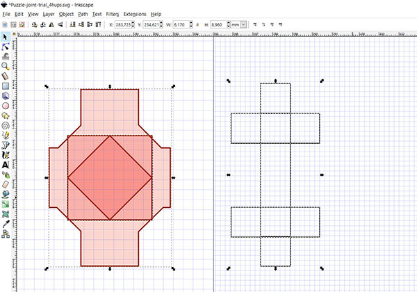
For sending the file to the laser cutter, on a computer I:
- Opened the .pdf -file of my design, and
- Selected a printer to be "Epilog Engraver WinX64 Fusion" and hit Properties.
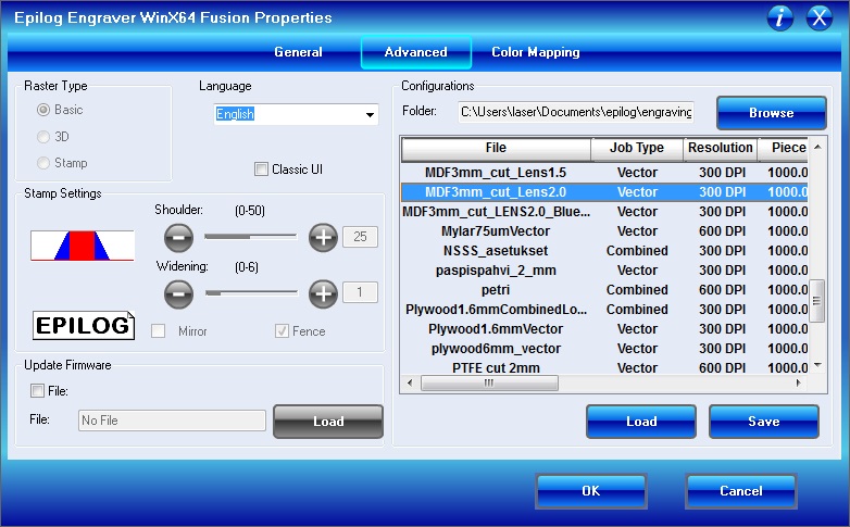
In the Properties // ADVANCED -tab, I need to:
- Select and Load the material. Just to make sure, I checked the thickness of the material I was going to use by the caliper.
- This time I used MDF 3mm (MDF3mm_cut_Lens2.0), since I have an ongoing project where I am going to use that, too).
- When selecting the material, default settings and values for cutting are loaded, including cutting speed, power and frequency, which for I could refer.
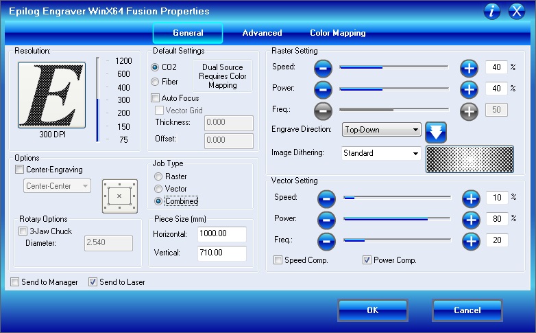
Next, in the Properties // GENERAL -tab, I need to check the correct box of:
JOB TYPE
- Depending if cutting only 'Vector', or if 'Combining' cutting Vector and engraving 'Raster'.
OPTIONS
- Select 'Center Engraving' option in order to define the origing of the laser head in the material to start from the center of the design file.
- If not selected, the origin will be the top left corner of the design file.
VECTOR SETTING
- This time I used the default settings for the material MDF 3 mm (Speed: 13 %, Power: 80 % and Freq: 20 %), since in the group assignment we defined them to be the best based on the cutting quality and kerf results.
- SPEED defines how quick the laser moves through the material. Slower speed gives deeper cut on the material but too slow speed might burn the cutting edge of the material.
- POWER defines the power of the laser beam. Again, more power gives deeper cut on the material, but too much power might burn the cutting edge of the material.
- FREQUENCY defines the frequency of the laser pulses.
After checking all of the settings, I hit OK which sent the cutting file and parameters to the laser cutter.
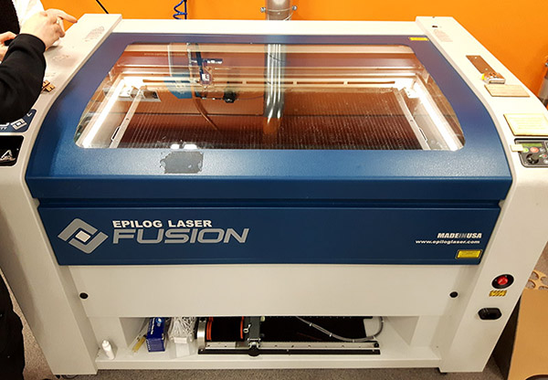
At Fab Lab Oulu, we have two laser cutters ,Epilog Laser Fusion 75W CO2 and Epilog Laser Mini 24. For this assignment I used the bigger one, Epilog Laser Fusion.
For setting up the laser cutter, at first I have to:
- 1) Turn ON the laser cutter
- 2) Switch ON the SUCTION SWITCH and
- 3) Make sure that AIR VENTILATION is ON (CRUCIAL TO CHECK BEFORE CUTTING!).
- 4) Check where the emergency stop -button of the machine is located.
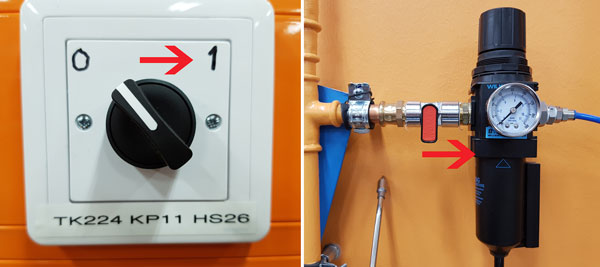
Then, I placed the material I am going to use on the laser cutter. If material is bended, I can try to make it flatter by using some blue tag or weights placed safely in there, where the laser won't go for sure.
In the laser cutter's user interface (UI), by the two white arrows pointing up and down I need to select the origin, calibrate the focus of the lens and select the job from the printing queue, which I will adjust and set by the joystick:

JOG
- By pushing the joystick and find the middle spot of the cutting area to be cut to set the focus of the lens
- Middle spot is used for getting an average distance because the material used for cutting might be bended
FOCUS
- Set the correct distance between the laser and the material.
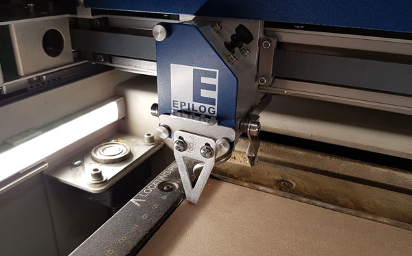
- Adjust the distance by using the triangle shaped manual calibrator placed on the laser head.
- By pushing the joystick, move the material bed up and down so, that the calibrator head will touch the surface of the material (won't hang in the air, nor move up at all), and when the distance is fixed press the joystick to reset the Z -value.
- Remember to remove the calibrator from the laser head after setting the focus.
JOG
- Find the spot to be used as an origin/ from where to start cutting (based on the 'Center Engraving' ON/ OFF).
- Push the red laser -button on the UI in order to see a visible laser light above the material showing the current origin.
- By pushing the joystick, find the origin by moving the laser head to the correct place being the upper left corner of the cutting file, and press the joystick to reset the XY -values and set the origin to be at that place.
JOB
- Select your job from the printing queue.
- When the job is selected, the display will show an estimated cutting time of the job.
When the settings are finished, press 'GO' and the laser cutter will start cutting.
Manual calibrator set on the laser head:
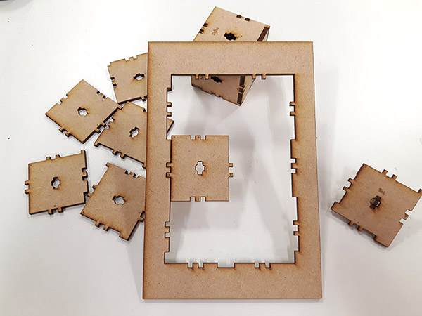
This LED cube light up by white LED, 3V coin battery and the circuit inside the cube is what I aimed with this project:
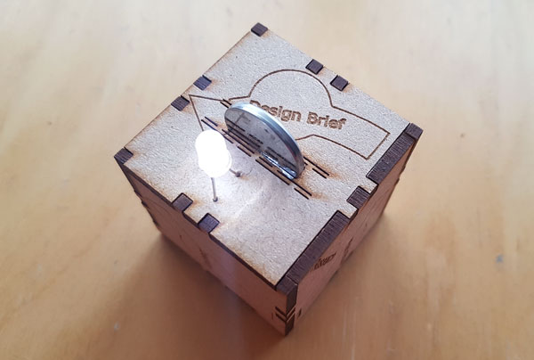
Even though I used the default settings - identified to be the best based on our group assignment kerf -test - the material was not full-cut. I think, either the material was a bit bended OR, the material won't lay straight on the most used upper left corner of the laser cutter (I even used a blue tag to hold it still), but rather it will be a bit bended up. This will cause a mistake to the FOCUS, if the distance for the laser of the material is set in that corner but the actual height of the material is lower down. Then the height of laser is too high and the material won't be cut through.
Designing a parametric model with Autodesk Inventor
After finishing the model, I started to design the parametrical model with Autodesk Inventor. However, I had some problems in my design maybe because the puzzle pieces where a bit complex to start and I set too many parameters to my design.
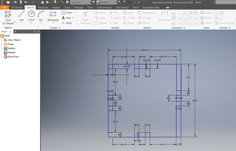
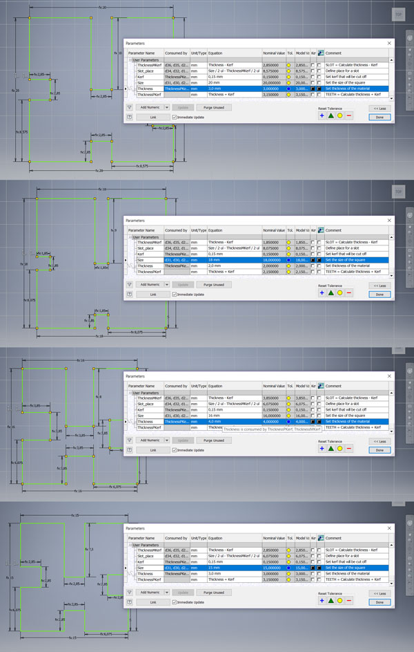
I ran out of time so, in the end I made a simple one-piece design just to get an idea of parametrical design and finish the assignment. From the top bar, by navigating in to Manage > Parameters I set the correct parameters, that I had measured and designed with Inkscape. Here are the User parameters incuding the Equations I set:

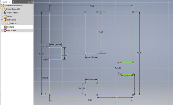
Then, I draw a rough design of the piece:
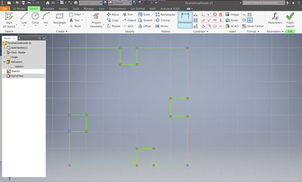
Further, I took Dimension -tool and selected which of the lines should be defined by certain parameters. I set the size of the slots to be defined by [the thickness of the material - kerf].
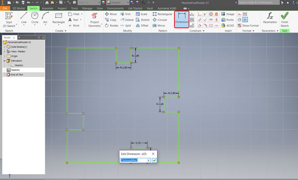
Further, I defined the size of the piece:
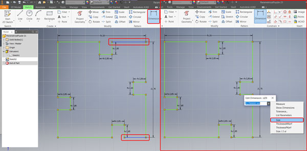
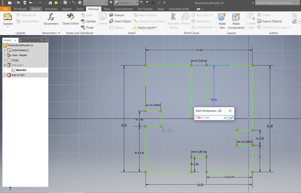
I defined the places of three of the slots to be in the middle of the sides by the equation [(Side / 2) - ((Thickness - kerf )/ 2)]. The fourth slot on the right side of the piece I defined to be fixed 5 mm from the bottom. In addition to small slots based on the thickness of the material, I wanted to make one halfway slot on top of the piece by setting an eguation [Size / 2]:
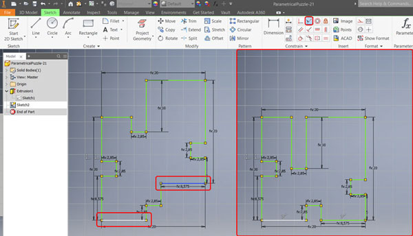
When I was setting the parameters, my design changed its form and to keep the square form I had to set some Constraints which for I used Collinear Constraint -tool to lie two certain line segments on the same line:
Here is the finished parametrically designed example piece for my press-construction kit:
The benefit of the parametrical model is that it makes possible to change values based on Material thickness and kerf as well as easily change the size of the piece or make any modifying for the place or size of slots just defining them again in the User parameters:
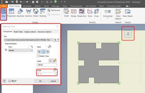
Arter finishing the model I prepared to make .pdf -file of the design for cutting the file. For that, in the design -file I selected File > New > Drawing. That opened me a Drawing file, from which I deleted a 'Default Border' and 'ANSI - Large' -layers to get empty sheet. By right-clicking over the sheet -layer and selecting Edit sheet, I changed the sheet size to A4.
Then, from the top bar, I navigated to Base View to create the first view in a new drawing. That opened me a new pop-up window, where I checked Scale to be 1:1. Furthermore, I rotated the design to be in right cutting orientation, dragged it into a upper left corn and hit OK.
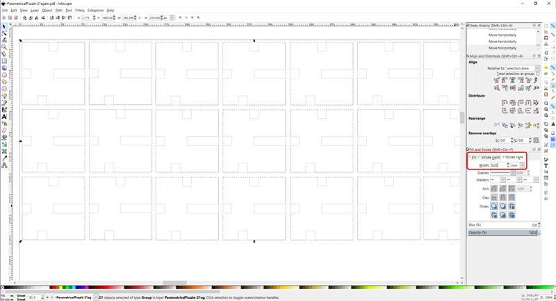
By selecting the area of the borders of the piece, I selected all of the lines at the same time, and by right-clicking over one of the lines I selected edge Properties and changed Line Weight to 0,02 mm. For creating .pdf -file, from the top bar, I navigated to File > Export > PDF.
For creating the cut file, I opened the .pdf -file in Inkscape. From the top bar, I navigated to Object > Fill and Stroke > Stroke style to check the line width, which was not correct so, I changed it again to 0,02 mm. Then, I multiplied the piece to cut 21 pieces at a time, and created the final cut file by navigating into File > Save As > PDF.
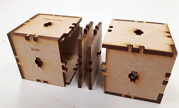
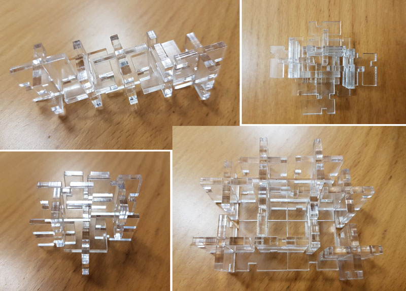
I cut the file and here are the results, my parametric press-fit construction kit, accounting for the lasercutter kerf, which can be assembled in multiple ways:
Vinyl Cutting
I decided to cut stickers for my Puzzle 'n Puzzle as well as for my final project idea, and I created a shared file combining both. For creating a file it is possible to use for example Adobe Illustrator, Inkscape or design a file straight in the Roland vinyl cutter's software Cut Studio.
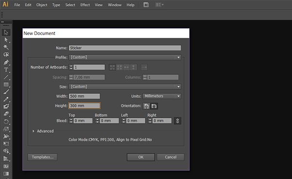
I designed my stickers with Adobe Illustrator CS6. I selected New File and defined Width: 500 mm and Height: 300 mm. Then, I selected Text -tool, designed the texts and modified the font and size of the text. I wanted to make my stickers as negative design which means, that I was going to remove those parts which I am drawing and use the frame of the design as a sticker. Vice versa, positive design means, that I woud use the parts that I am creating and remove everything around it. Especially when creating the negative sticker it is important that I remember to draw the outline of the sticker frame.
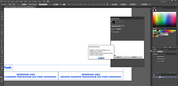
I tried to install CutStudio plug-in to my Windows 10, to be able to send and cut the file straight throug from Illustrator. However, it didn't work even though the plug-in appeared to extensions. I found out that in Windows the plug-in is not enough but I should have also the CutStudio software. So, I opened the file with Fab Lab's computer, to cut the file both with Inkscape and CutStudio.
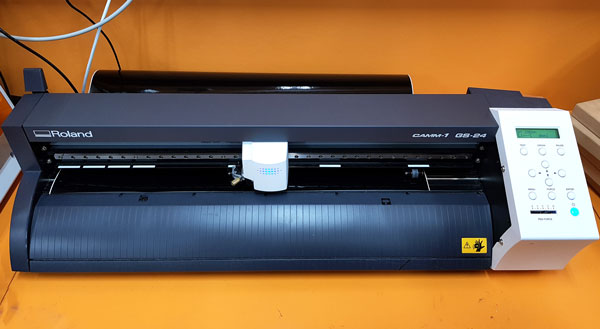
At Fab Lab Oulu, we have Roland CAMM-1 GS-24 vinyl cutter.
For setting up the vinyl cutter, I:
- placed a vinyl roll to the mount behind the machine so it moves smoothly above the rollers,
- inserted vinyl from the back side of the machine and placed its edge to the left side of the machine (zero),
- adjusted two support rollers so that they are placed on the white spots near both edges of the vinyl piece, and
- locked the vinyl piece with the lever on the left on back of the machine.
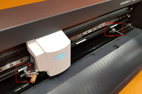
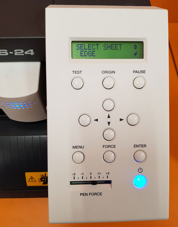
Then, I turned the machine on, and selected the sheet type as follows:
- Roll // when using a roll
- Piece // when using a piece of the roll, and
- Edge // finds cutting edges and is recommended to use always when I don't have a piece.
When using either Piece or Edge -option, the machine measures and detects automatically the edges of the vinyl.
- To find the edge of the piece of vinyl (or edge of the roll) press Edge and hit Enter in the machine UI
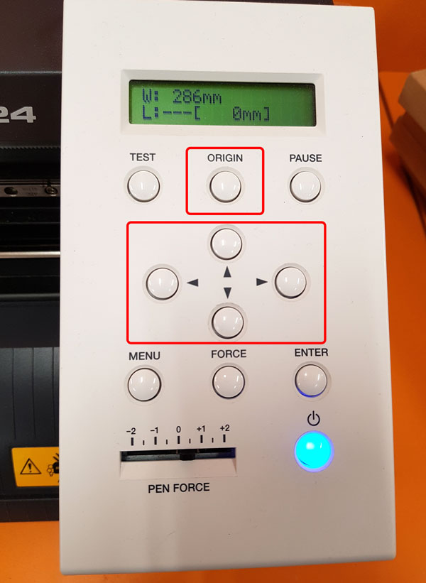
Then, I added New Origin to be a starting point of the cutting:
- Move the cutting head to the right horizontal position manually using the left / right arrows and
- press Origin and keep it pressed until the machine confirms Set
If the edge of the piece of vinyl is not straight e.g. there has been cut something already from the corner, I can adjust the support rolls based on the existing edges and then find new origin manually:
By the default, I set the Pen Force to be 0. However, if there would have been any problems in the cutting quality – e.g. it wouldn’t cut through - I could adjust the Pen Force. Now, the vinyl cutter has been set up for cutting.
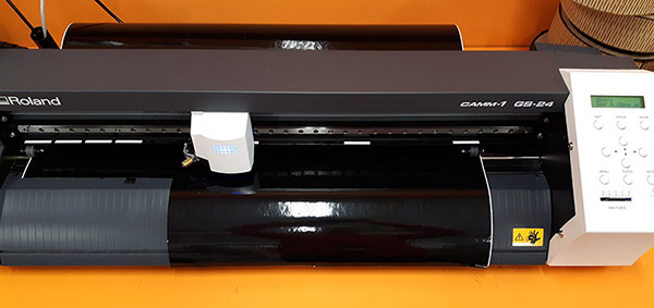
For cutting the stickers, I opened my svg -design file in Inkscape.
First, I could set document paper size to detect the size of my design in File > Document properties > Resize page to drawing or selection.
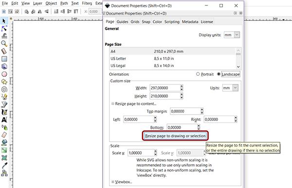
- Then I navigated to File > Print, selected the printing machine: Roland GS-24, and continued to Printing Preferences.
- I had to fix the Cutting Area Width and Length: Get from the machine.
- the width came from the machine when measured the edges [584,2 mm]
- the length has to be based on the size of the design plus a space for margins [~150,00 mm]
- Finally, I wanted my design to be cut in that direction as designed, so I have to remember to select Rotate: Off
- (However, you may need to check that the lenght is greater than the width or otherwise the machine will rotate the cut file 90 degrees to make the leght greater (which happened to me, since the Lenght I set was shorter than the Widht, and then I learned the difference).
--> I checked the height of the design and added a couple of centimeters for marginals.
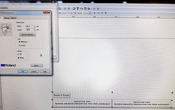
Another option I tried is to open a file in CutStudio. In this program you can both design and then cut the design.
Here, I imported the picture from the folder:
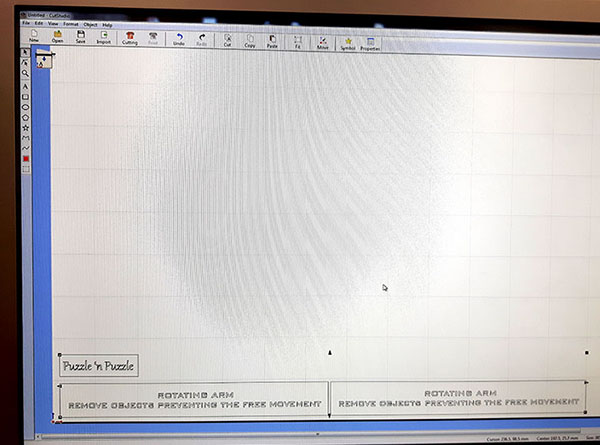
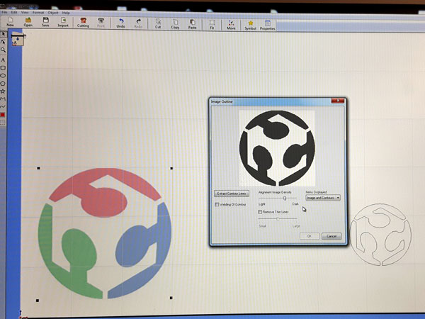
Here, the picture to be cut is copy-pasted:
- Above the picture, I right-clicked a mouse and selected Image Outline.
- Then, I adjusted Alignment Image Density between Light and Dark to get only outlines, and hit 'OK'.
- I moved the vectored picture above and removed the original picture below.
- Finally, I pressed “Cut” and “OK”, and the machine started cutting.
It is possible to copy-paste a design created in Inkscape to CutStudio also, but the quality will be poor since the edges of the design will be serrated.
After cutting the stickers, I removed the unnecessary parts of the stickers. I learned that once cut, we should never leave the stickers without cleaning the extra parts because glue can stick them to each other again afterwards.
Stickers for my final project 'A Rack for 3D Scanner' (which later on changed to be another project):
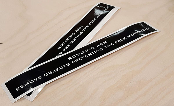
A Sticker for my Puzzle 'n Puzzle:
After cutting, originally, I could cut the cut piece horizontally and remove whole slide but this is not necessary. I can spare vinyl if I remove only the cut piece of vinyl and next time move support roll to start from the edge of previous cutting line and use Edge to measure the size.
Group Assignment
As a group assignment we were supposed to characterize our lasercutter, and make test part(s) that vary cutting settings and dimensions in order to identify the Kerf or the laser in different settings.
The documentation of our work can be found from the group site.
Git-LFS
For uploading large files to the Git repository in a appropriate size, I downloaded GIT extension called Git Large File Storage (Git-LFS) and integrated Git-LFS in Git:
git lfs install

Then, I defined which file formats should be tracked with the lfs (the formats that I don't want to include directly in the Git repo). I decided to track .stl , .mp4 , .ipt , and .ai :
git lfs track '*.[format]'
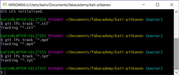
After that, I was able to progress as usual, and do the add and commit for all files (including the files to be tracked with the lfs) as normal in Git repository.
Here are the design -files I made this week:
- Puzzle Cube (.pdf) // Test design with Inkscape
- Example Piece (.ipt) // Press-fit construction kit designed with Autodesk Inventor in ipt format
- Example Piece (.dwg) // Press-fit construction kit designed with Autodesk Inventor in dwg format
- Example Piece (.svg) // Press-fit construction kit cut designed in Inkscape in svg format
- Example Piece (.pdf) // Press-fit construction kit cut file in pdf format
- Stickers (.pdf) // Stickers for the Rack of 3D Scanner and Puzzle Cube designed with Adobe Illustrator in pdf format
- Stickers (.svg) // Stickers for the Rack of 3D Scanner and Puzzle Cube designed with Adobe Illustrator in svg format
- Stickers (.ai) // Stickers for the Rack of 3D Scanner and Puzzle Cube designed with Adobe Illustrator in ai format

