
Kati Pitkänen @ FAB LAB OULU · 2018
© 2018 Kati Pitkänen · Template by Bootstrapious

This work is licensed under a Creative Commons Attribution-NonCommercial-ShareAlike 4.0 International License.
Networking and Communications
Week 15 · [ 25.4.2018 - ]
- Design and build a wired &/or wireless network connecting at least two processors. (Individual Project)
- Send a message between two projects. (Group Project)
This week I made a network between my ATmega328P Flower -board and three other Flower boards: another ATmega328 and two ATtny45 boards. I learnt to establish a serial communication between several microcontroller boards. Further, I learnt difference between Serial and mySerial, which are the two communication lines from the Bridge board i) to a computer and ii) to nodes.
I had quite a lot challenges in trying to finish the assignment quickly, and the broken light sensor board didn't help troubleshooting at all. I am thankful to my fellow student Jari Uusitalo and our local instructor Iván Sánchez Milara and Antti Mäntyniemi who helped me in troubleshooting when I was stuck. Finally, I managed to setup and partially implement my idea of the network.
Then I got pretty excited and wanted to continue further and still try to make my initial idea working. I did not want the nodes response only by blinkin an LED on the node board to know that I got your request but I wanted to see the response also on the bridge board and further, on the computer. For this, I wanted to ask the environment lightness information from the light sensor node, and finally I succeeded in implementing the idea and getting nice responses on the serial monitor on computer: i) which node is responding to request sent on the serial communication line, and ii) what information it returns to serial monitor. I was fashionated about this success of an attempt and all this learning, and I could have continued that path further for a long time.
Even the week was challenging, I really enjoyed this topic, and I am looking forward to have more time for immersion on the networking. For this, my next step will be in asking temperature from the temperature sensor node.
Networking
Our local instructor of the week was Juha-Pekka Mäkelä. During the actual week I was in Denmark, participating in their fantastic FabLearn DK 2018: Computational Empowerment in Learning Communities conference, so I had to finish the assignment afterward. Fortunately, I prepared and fabricated all the necessary boards alresy on the Week 12 - Input Devices so I could focus on programming part this week.
Antti illustrated us a very simple, nice picture of the idea, what is happening in networking between the boards. I draw this picture again to add my own boards:
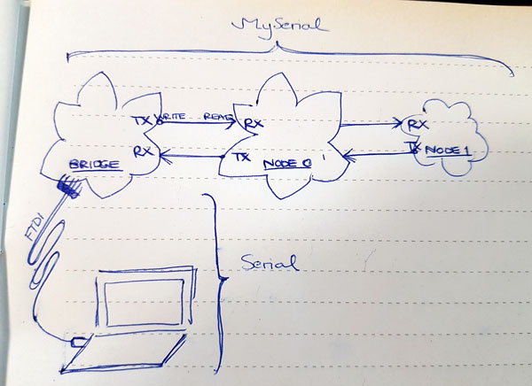
- BRIDGE board, master // ATmega328P Flower -board, connected to computer by FTDI-USB -cable
- TWO NODE boards, slaves // temperature sensor board and light sensor board
- FTDI -cable of 5 Volts // for powering the boards through master board
- Arduino IDE // for creating the code
The idea on networking is that when the bridge is calling any node (I am typing something into a terminal on my computer):
- The terminal sends the request via network cable
- Then, all the nodes are listening the network and the message reaches each of them.
- When the certain node recognizes that it's been called by the bridge, it functions normally as an INPUT and receives the message.
- Then, for a short moment, when the node is transmitting the answer for request, it turns to be an OUTPUT
- and right after it will turn to be the listening INPUT again.
- The other nodes, not called this time, will pass the request since it is not for them and continue listening the network cable.
Physically, I formed the network by connecting my sensor boards to my ATmega328P Flower -board (the master board) with serial cable (sensor bus connector cable), which has two signals on its bus sensor header:
- TX for transmitting the data from the master to the node board // sending the command or request to the sensor board and
- RX for receiving the data from slave to the bridge board // receiving the value from the sensor board
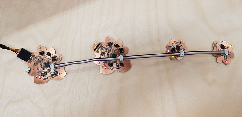
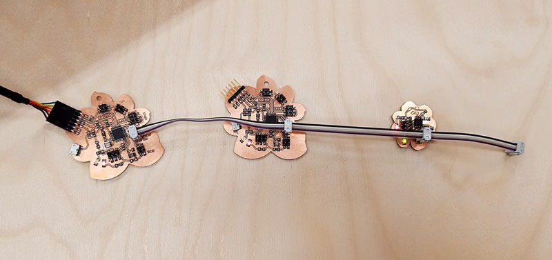
Here is the setup I prepared for networking:
- ATmega328P board connected to the computer by FTDI -cable // for powering the board [the red LED is indicating that the board is powered]
- ATmega328P board connected to USBtinyISP -programmer // for programming the code to call the sensor boards
And by sensor bus connector cable, serial line from ATmega328P bridge board to the following boards:
- ATmega328P II board // lighting up LED and transmitting a response to the serial monitor
- ATtiny45 temperature sensor board // transmitting a response to the serial monitor
- ATtiny45 light sensor board // sensing lightness and transmitting a response on the serial monitor
Instead of using FTDI RX- and TX -pins on the Bridge board for serial communication, I have reserved this connector for bluetooth.
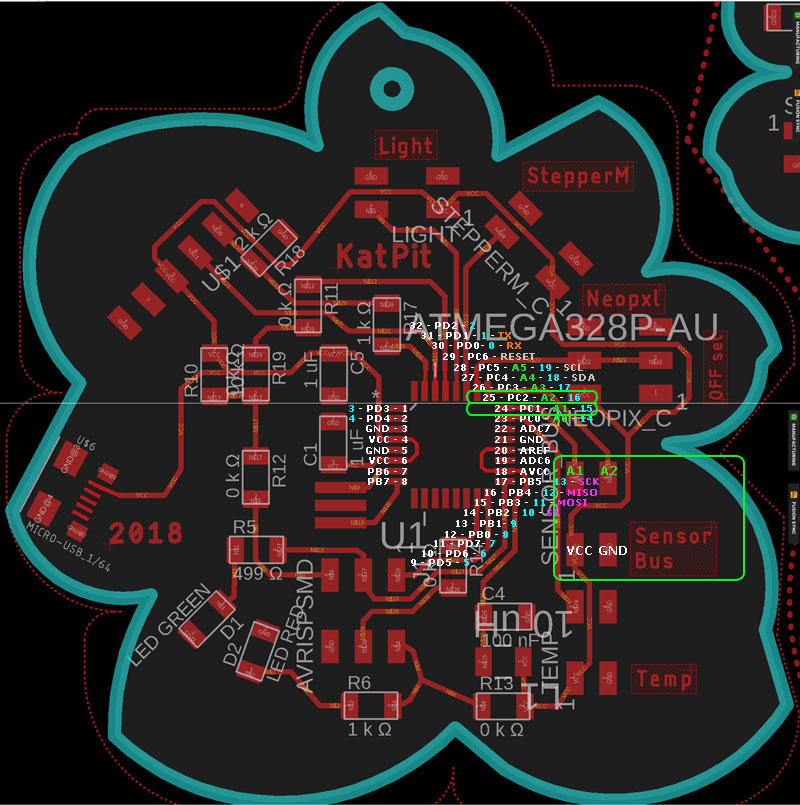
For serial communication, I used a separate Sensor Bus connection [ATmega328P Schematic: TX = PC1, RX = PC2].
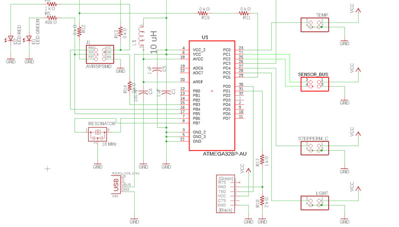
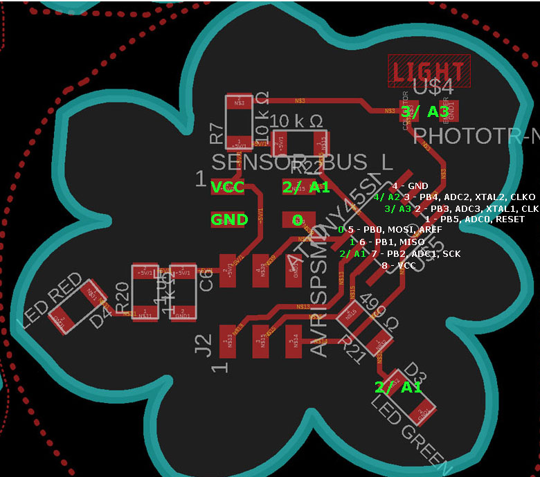
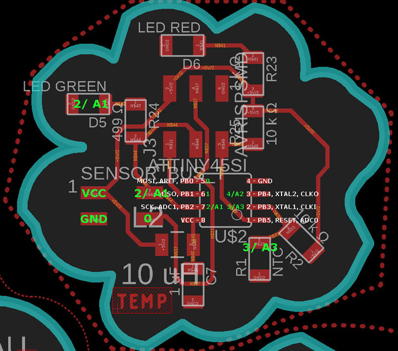
Here is my pin configuration presenting the pin header connecting the node boards to ATmega328P bridge board:
And here are the nodes and their pin headers:
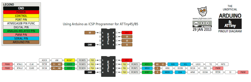
One of my challenges during the week was using the wrong pin mapping. I thought that I had correct Arduino compatible pin mapping in use but it was the wrong one. The issue was solved by fixing the pin numbers on the code. Here is the Arduino & ATtiny pin mapping I obtained from Elec-Cafe.Com.
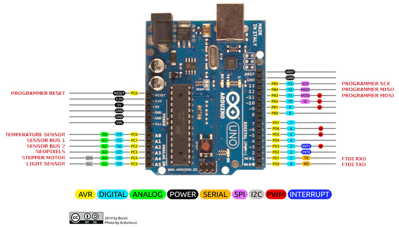
And here is the pin mapping I obtained from Bouni and added the pins of my ATmega328 on the sides of it. In the beginning of programming ATmega328 board I was using AVR pins by mistake, so the LED did not light up. After fixing the pins, many issues were solved and I had learnt a lot again.
Programming
I started my programming on reading Arduino SoftwareSerial Library Tutorial. Moreover, I learned the idea of networking by reading previous year students documentation, such as Jari Pakarinen and Nataliya Shevchuk, and obtained my fellow student Jari Uusitalo's code to get started.
The first setup of the network consisting of the Bridge and the two node boards.
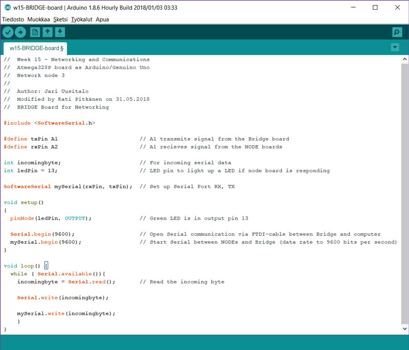
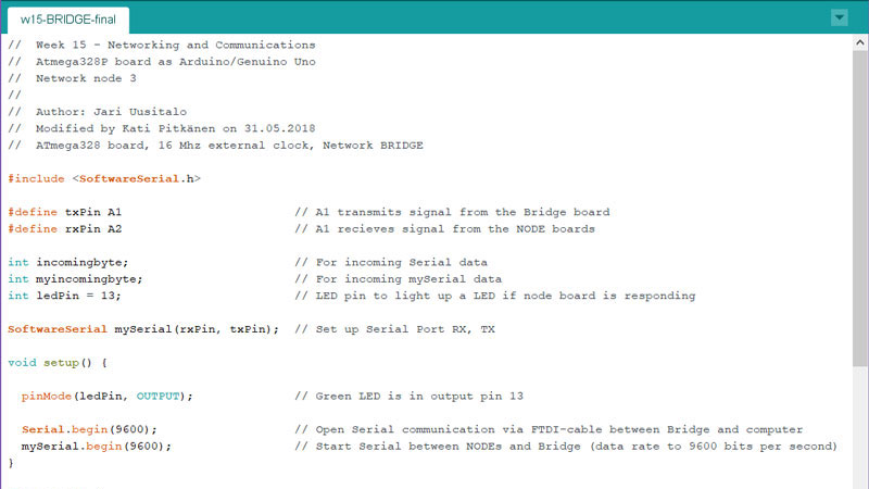
I created the first code for my Bridge board based on Jari's code and Iván's help. At this phase, I did not managed to send the data, such as light sensor value based on threshold, and temperature sensor value. However, I made the three boards networking, and light up a LED on the node board based on request from the Bridge board.
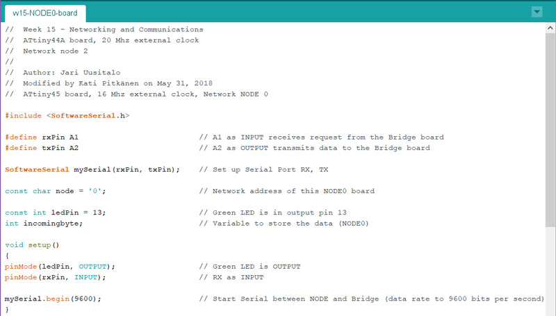
Here, I have defined the transmitting pin #define txPin A1, and the receiving pin #define rxPin A2. Then, I have defined the variables for incoming serial data int incomingbyte: and the LED pin to light up a LED when the NODE board is responding int ledPin = 13;.
Moreover, there is setup the port for Serial SoftwareSerial mySerial(rxPin, txPin);.
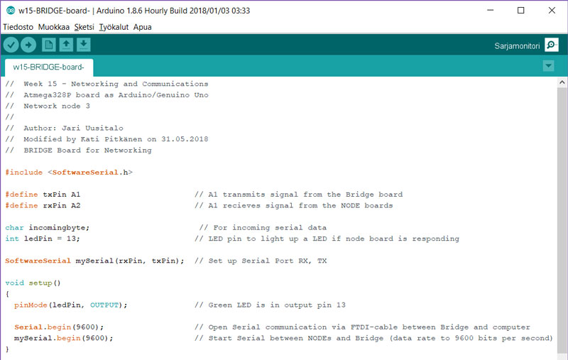
In void setup I have set the green LED being in OUTPUT pin 13 pinMode(ledPin, OUTPUT); and started Serial between the Bridge and computer (baudrate 9600 bps) Serial.begin(9600): as well as the Serial between the Bridge and the NODEs.
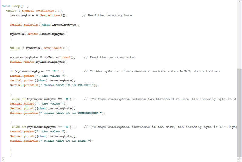
In void loop the Bridge is reading the incoming byte, and writing it into the Serial.
The Bridge, that is sending a request through Serial communication cable:
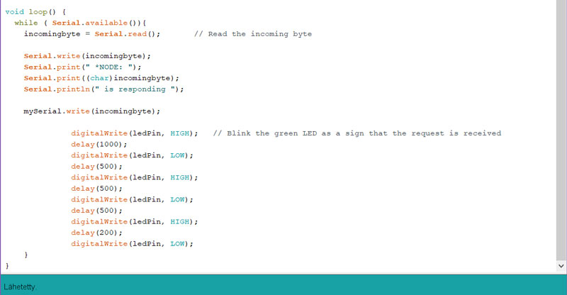
Then, I developed the code further to blink LEDs in both ends - on the NODE as an response that I got the request and on the Bridge as indicating that the request is sent. Also, instead of reading zeros and ones on the serial monitor, I added a print line commenting which node was called.
  void loop() {
  while ( Serial.available()){
  incomingbyte = Serial.read();       // Read the incoming byte

    Serial.write(incomingbyte);

    Serial.print(" *NODE: ");
    Serial.print((char)incomingbyte);
    Serial.println(" is responding ");

    mySerial.write(incomingbyte);
For the beginning, I defined the RX- and TX -pins and variables, and done the void setup as documented above.
In void loop I am listening the serial line by while (Serial.available()) { and reading the incoming byte by incomingbyte = Serial.read();. Then, the Bridge is writing to Serial some information lines including the information coming from the responding NODE board, and blinking the LED as a sign that a NODE has received the request.
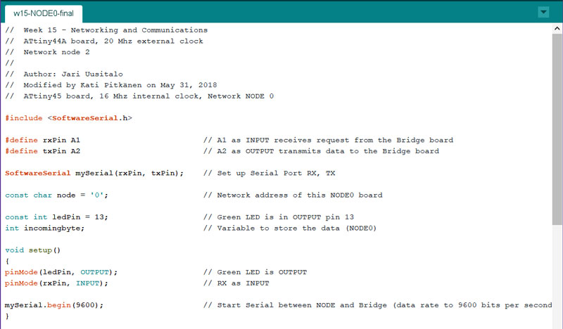
This is the code for NODE0, which is identical ATmega328 board with the bridge board. First, I tested that my serial communication boards and communcation lines where working just by sending and receiving some data with Arduino Software Serial Example. Then, I utilized Jari's code as a base of my code for NODE0.
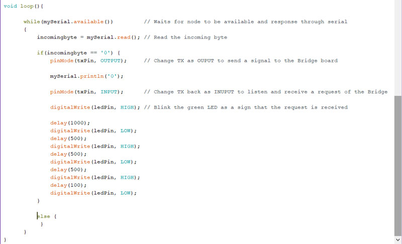
Here, the NODE is reading an incoming byte sent from the Bridge. Then, because the NODE is normally all the time as an INPUT mode, it needs to be changed to OUTPUT mode sor a moment to be able to sent the response for the Bridge. After sending the response, the NODE will be changed again to INPUT mode.
After that, the NODE is also blinking a LED as a sign and OUTPUT that it has received the request from the Bridge.
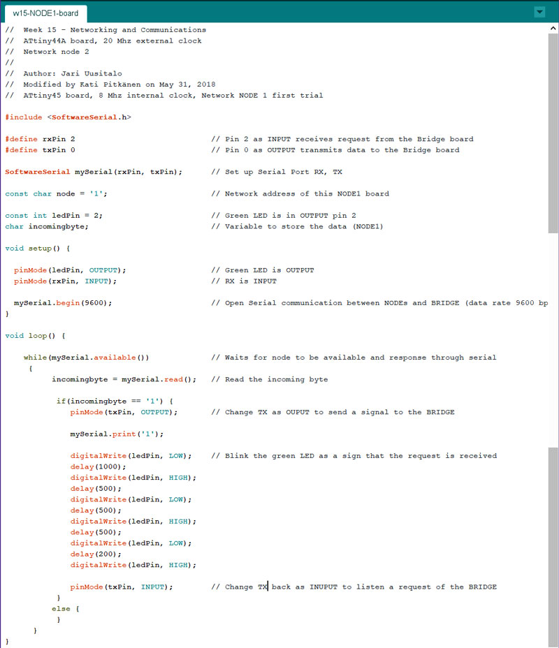
This is the code for NODE1, which is ATtiny45 board. I utilized Jari's code as a base of my code for NODE1, too. However, here I faced a challenge, because it happens to be so that the RX pin is same than ledPin. This means, that since the RX -line is ON, also the ledPin is ON all the time when the line is waiting for a possible request. First, I tried to solve the issue by reversing all RX- and TX -pins in all boards, so I got the LED OFF. However, this was not working. Then I checked all the ints and chars, pin numbers etc with no result.
Finally, the reason was in setting the serial line to be INPUT all the time, which made the LED be ON all the time as well. When
pinMode(txPin, INPUT); -row was set after the LED blinking phase (instead of right after printing the
information of node number), it allowed the LED actually perform the action, and then the serial line was set to be INPUT again. Moreover, by mistake, the INPUT-OUTPUT line
was set to be RX at first, even it shoud be the transmission line TX that changes to be INPUT and then back to OUTPUT. After fixing all these frustrating mistakes, and increasing
my understading about the principles of networking, the wheels started to move on a bit smoother.
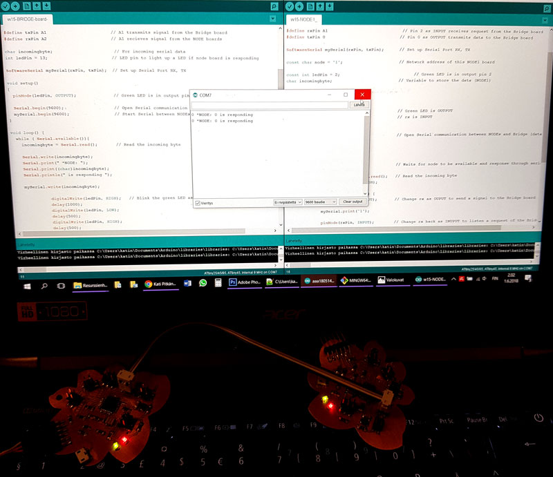
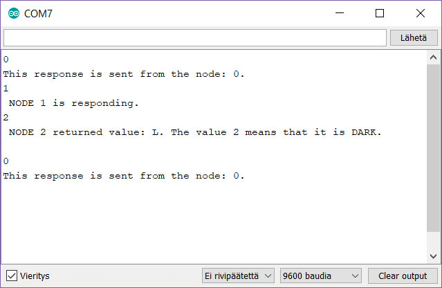
After learning the principles of networking I got quite inspired about it and wanted to discover and learn a little bit more. My fellow student Jari was very nice helped me to take the next step, and replied and confirmed me all the questions I had when building my understanding on networking. Finally, I learned to read and understand the code, and I was able to search and do experimenting further by myself.
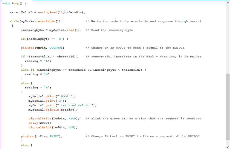
This is where I got this time: (There is one error on the picture, though. At that time the description of the values was reversed, because 'L' should return BRIGHT.)
This is the developed code for BRIDGE, which is ATmega328 board. Here, I have added what will be written on the Serial monitor based on what the node transmits to the Bridge through the mySerial line. This serial communication includes the light sensor boar as NODE2, which for there is lines for writing into a Serial if acoording to a measured value the environment of a sensor board is BRIGHT, SEMIBRIGHT or DARK.
The details of the code can be seen as commented lines on the screenshot below.
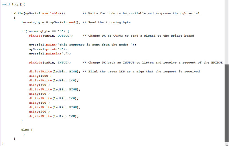
This is the improved code for NODE0, which is ATmega328 board. Here, I have improved the line transmitted to mySerial line for Bridge having a more descriptive response.
  if(incomingbyte == '0') {
  pinMode(txPin, OUTPUT);     // Change TX as OUPUT to send a signal to the Bridge board

  mySerial.print("This response is sent from the node: ");
  mySerial.print('0');
  mySerial.println(".");

  pinMode(txPin, INPUT);      // Change TX back as INUPUT to listen and receive a request of the BRIDGE
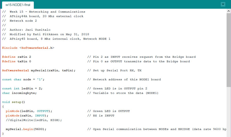
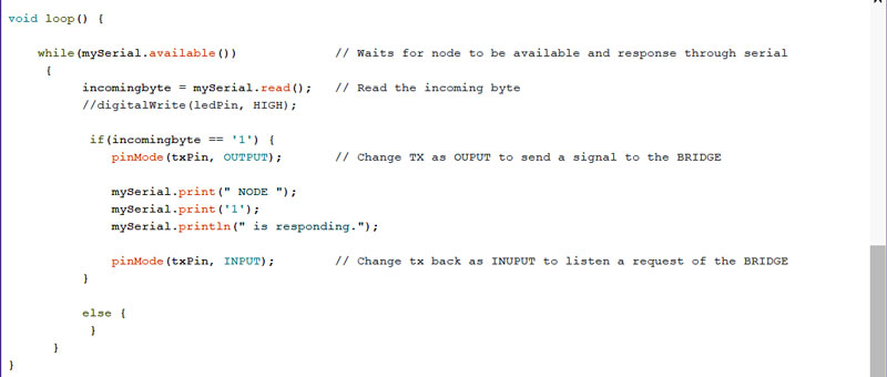
This is the code for NODE1, which is ATtiny45 board. I have improved the line transmitted to mySerial line for Bridge having a more descriptive response in here as well.
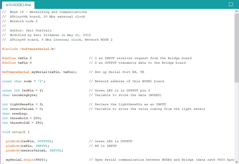
And this is the code for NODE2, which is ATtiny45 board. This is the light sensor node board on the network. For this, I utilized the same basic idea of the light sensor code on the Week 11 - Input Devices originated by AR Builder in the networking code. The light sensor will read the sensorValue and transmit the information on which of the three value range the amount of the environment lightness is.
The most important things I learned is to check twice that you are using the correct in mapping to not make troubleshooting too frustrating.
Also, remember to write the serial communication line so that what the Bridge board transmits (tx pin), the node receives (rx pin), so those pins have to be assigned on the same line.
Here are the first round programming codes of my Network I programmed on this week.
- Bridge board requesting nodes to give a sign by blinking
- Bridge board blinking together with the requested node after response of the node
- NODE0 - ATmega328 board blinking the LED
- NODE1 - ATtiny45 board blinking the LED
Here are the second round programming codes of my Network I programmed on this week.
- Bridge board requesting nodes to response
- NODE0 - ATmega328 board blinking the LED and responding on serial monitor
- NODE1 - ATtiny45 board responding on serial monitor
- NODE2 - ATtiny45 board responding on serial monitor
Here are the files of my ATmega328 Flower -board and the sensor boards I made on the Week 12.