
Kati Pitkänen @ FAB LAB OULU · 2018
© 2018 Kati Pitkänen · Template by Bootstrapious

This work is licensed under a Creative Commons Attribution-NonCommercial-ShareAlike 4.0 International License.
Input Devices
Week 12 · [ 4.4.2018 - ]
- Measure something: add a sensor to a microcontroller board that you have designed and read it. (Individual Project)
- Measure the analog levels and digital signals in an input device. (Group Project)
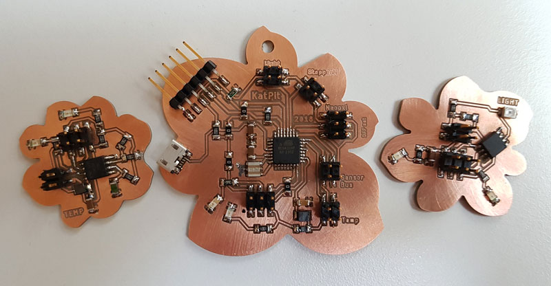
This week was huge. Keeping my final project features in my mind, it took a long time to design a board having ATmega328P microcontroller and necessary connections and components. However, in the end I am very satisfied with the result. I was glad that I managed to design the boards I needed on the same schematic. There was some small challenges and mistakes I made but through them I learned to understand the principles of designing boards in Eagle a bit better and avoid those mistakes later on, and make some consideration if starting to make several boards on the same design file next time. I found, that having a shared design file for several boards has its advantages in seeing the whole and cutting the boards at once. However, it has its limitations too, where you have to be very sure about having a correct milling values, having a flat surface of the milling machine plate, and succeed in attaching the PCB perfect to avoid the board bending and cut unevenly, especially if going to cut big boards. Also, the increased physical size of the PCB shield to be cut makes it even more crucial to manage to set the shield evenly.
However, I was quite busy when I made two sets of designing, milling, and soldering components for this week - the final project and the next few weeks in my mind. Moreover, for the first time I experienced and learned to use Mods for creating the .rml -files for milling machine.
Soldering was quite succesfull process this time and I found out that the reason was in using small, thin point of the soldering iron instead of the 'normal' one I used on the weeks 5 and 7. Also, I tested and learned some new technics how I should do the soldering for different type of components. Programming part was a bit tricky but finally, after I realised that I was using wrong pin mapping (the one for ATmga328P instead of the right one for Arduino UNO which I had bootloaded inside my microprocessor), it was easier to find out if the code works or not. Finally, I managed to program my temperature sensor board.
Ideating and Planning a Main Circuit Board and Sensor Boards of Temperature and Light
Since the beginning of this week's assignment, as our local instructor Juha-Pekka Mäkelä warmly suggested, I tried to take into account our final project features to try to make the board for the final project. I started by figuring out, which microprocessor I will need for my final project. I was considering, that I need several I/O-ports (input and output ports) and enough memory for programming and controlling over a number of LEDs, a temperature sensor, a phototransistor and a stepper motor. So, the microcontrollers we have used on earlier weeks, ATtiny44 and ATtiny45 are too small for that. Instead, I considered using ATMega328P which is the one that Arduino UNO is using as well and, it would be great to learn to understand and use this more powerful board.
At the same time, I started to list concrete what are the required components in total and external boards in addition to the main board, that I will need for my final project. At the first designing round of this week, I decided to make one main board with ATmega328P microcontroller, a simple light sensor board, and a couple of different temperature sensor boards to connect on main board pin headers without any microcontroller. Further, in addition to necessary FTDI and AVR ISP -connections, I wanted to include Bluetooth connection and micro-USB on the board. Our local instructor Antti Mäntyniemi helped me in understanding what was needed to realize this. By his advice, I added a voltage divider to connect my HC-06 (ZS-040) bluetooth module, that is a 3.3V device, to a 5V ATmega328 via FTDI connection. I created this voltage divider using two resistors: one 2K ohm and 1K ohm resistors.
"The HC-06 breakout board has a 3.3v regulator that allows a larger input voltage to be used, in the range of 3.6 to 6 volts. The RX pin can still only accept 3.3V though. --- The Arduino will read 3.3V as a HIGH so the HC-06 TX pin can be connected directly to the Arduino." (Martyn Currey: Arduino and HC-06 (ZS-040))
At the second designing round, I improved the first setting of the boards. Now, I added microcontrollers also on the sensor boards. Moreover, I made one of the pin header connections, that had two signal lines, a sensor bus connector for networking between the boards. To make the several connectioncs on the main board user friendly, I named them next to the pin headers.
Designing and Drawing with the help of the Microcontroller Datasheet
I checked 8-bit AVR Microcontrollers ATmega328/P DATASHEET SUMMARY datasheet and ATMEL 8-BIT MICROCONTROLLER WITH 4/8/16/32KBYTES IN-SYSTEM PROGRAMMABLE FLASH DATASHEET to learn this new microcontroller.
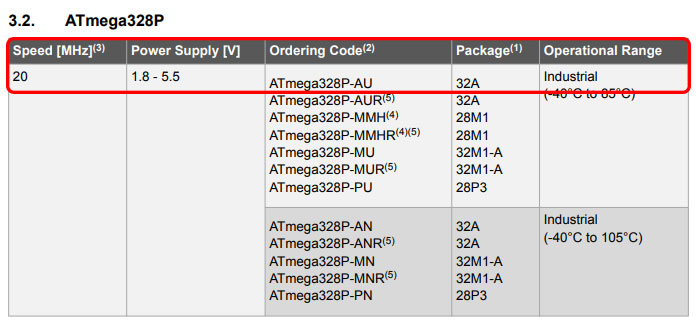
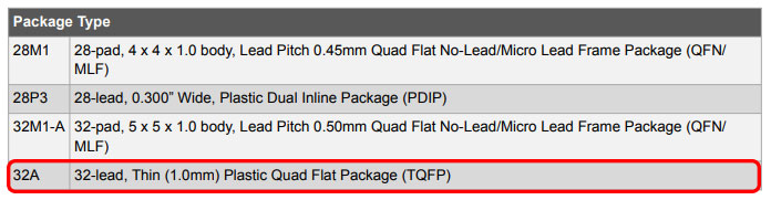
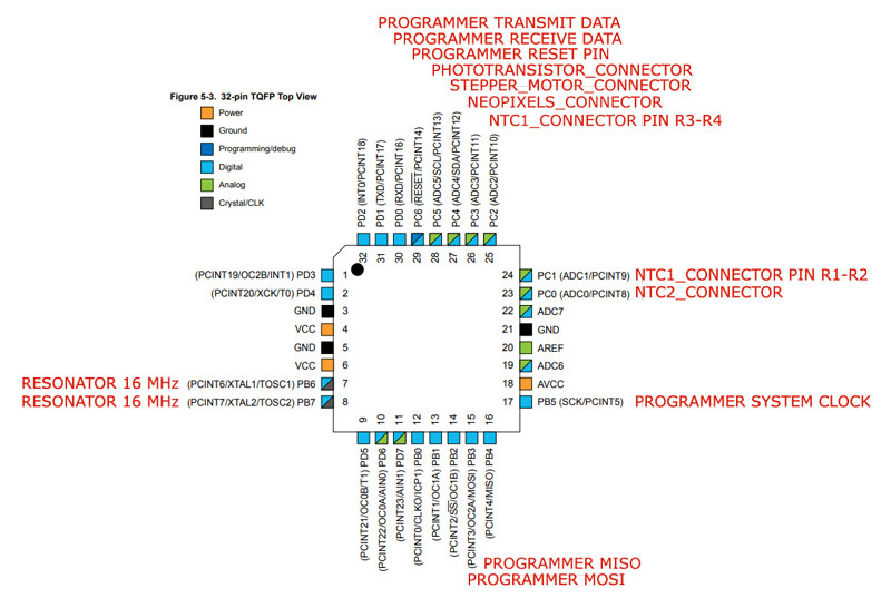
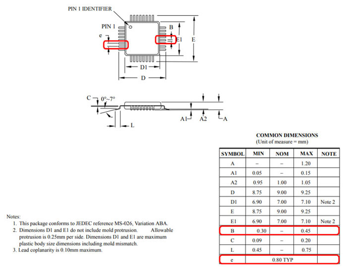
We had ATmega328P-AU in the stock. From the datasheet I found that it is Package Type 32A, which game me information that the microcontroller is 32-lead, ThinPlastic Quad Flat Package (TQFP):
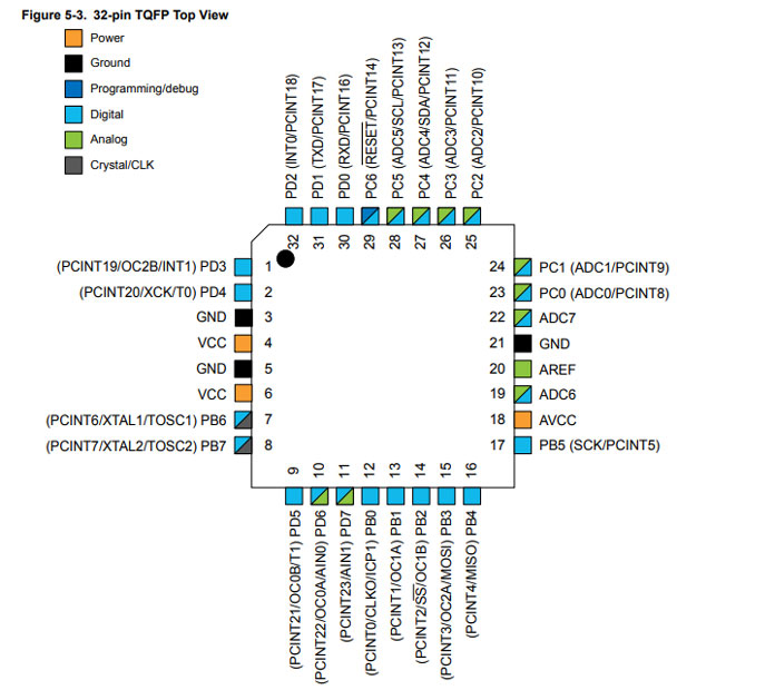
With that information, I was able to check correct top view and pins of 32-pin TQFP obtained from the Datasheet:
The most time-consuming part of this week was to figure out and design the board schematics and layouts. It was already easier to find the datasheets of components and learn them but I stil don't master understanding all of the 'additional' components needed, such as necessary resistors, capacitors and inductors, which for I got great help from our instructors Antti Mäntyniemi and Juha-Pekka Mäkelä.
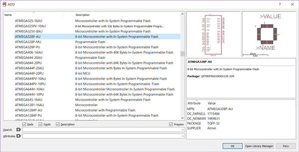
I used Autodesk Eagle 8.6.3 to draw the Schematic and Board Layout of one main board and three sensor boards. I followed the same design process as in the Week 7. I searched all of the main components, such as a microcontroller, sensors, pin headers and so on by 'Add' -tool and placed them nearby where they were going to be located in the schematic. For microcontroller, I downloaded the Atmel_By_element14_Batch_1-00.lbr -component library and added it to the Eagle installation folder (C:\EAGLE 8.6.3\lbr). Then, I navigated to Libraries > lbr and activated the library by right-clicking it and selecting Use.
From the Atmel_By_element14_Batch_1-00 -library I added:
From the fab library, I added:
From the element14 library, I added:
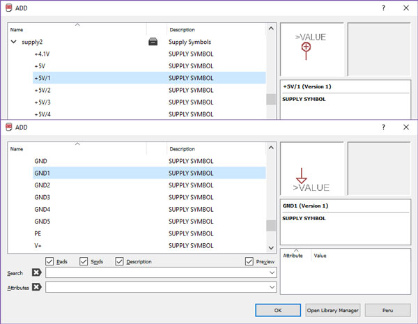
From the 'supply1' -library I added:
Then, I wired the components by the Net -tool. By right-clicking above the component and selecting Properties I named the components and gave them correct values. For some of the components, I had to give the correct value by right-clicking above the component and selecting Value.
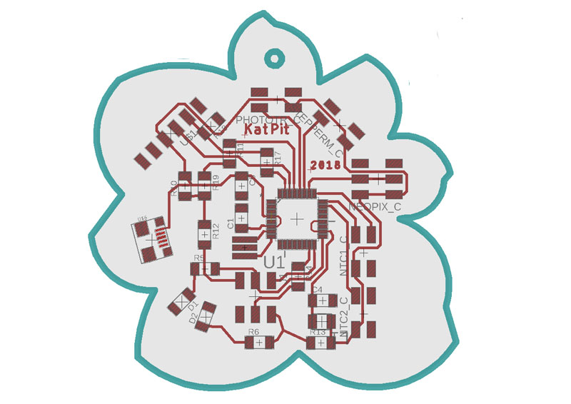
Here is the 32-pin TQFP Top View I obtained from the Datasheet, and the pin connectors according to my Flower Board design.
I considered, that I would like to design all of the boards for same schematic to see and understand the whole. That way, I was able to see how the connectors on the main board and on the sensor boards match together.
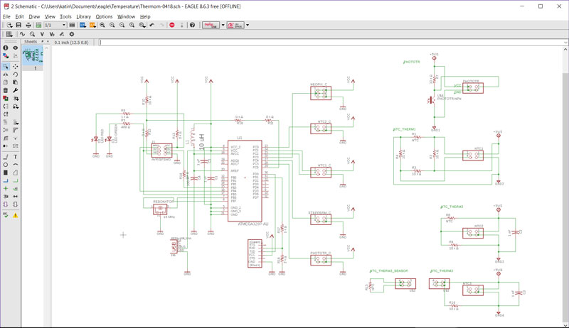
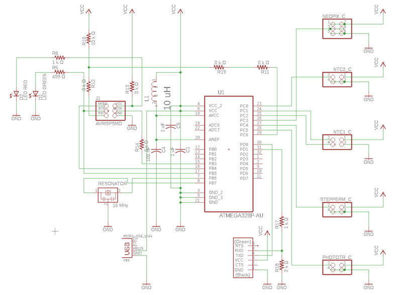
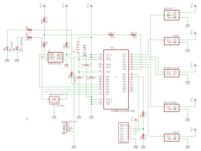
Here is my finished schematic desing of the Flower Board:
A Phototransistor NPN sensor board:
![]()
And the three dirrerent NTC temperature sensor boards for comparing the results, where the first one has a Wheatstone bridge. I wanted to rotate the NTC and other resistors 45 degrees but it seemed that there is no way to rotate in the Eagle schematic editor in any angle other than 90 degree increments. To figure out the schematic I got help from Dorina Rajanen's documentation.
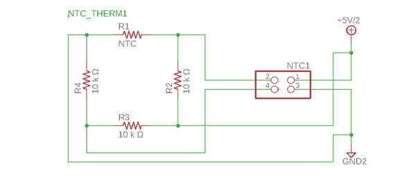
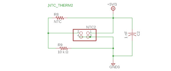
The primary benefit of a Wheatstone bridge is its ability to provide extremely accurate measurements, which I am curious to test and compare with a normal temperature sensor having only a NTC and one resistor, plus a capacitor to level down the values:
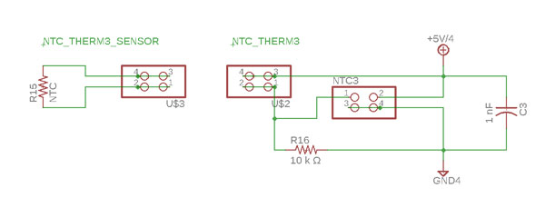
The third NTC temperature sensor board is just divided to be two-piece board, where only the NTC is aimed to put outside of the window via cable being at the mercy of weather conditions when measuring outside temperature, and the resistor and capacitor will stay inside the house.
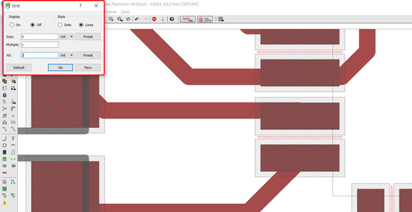
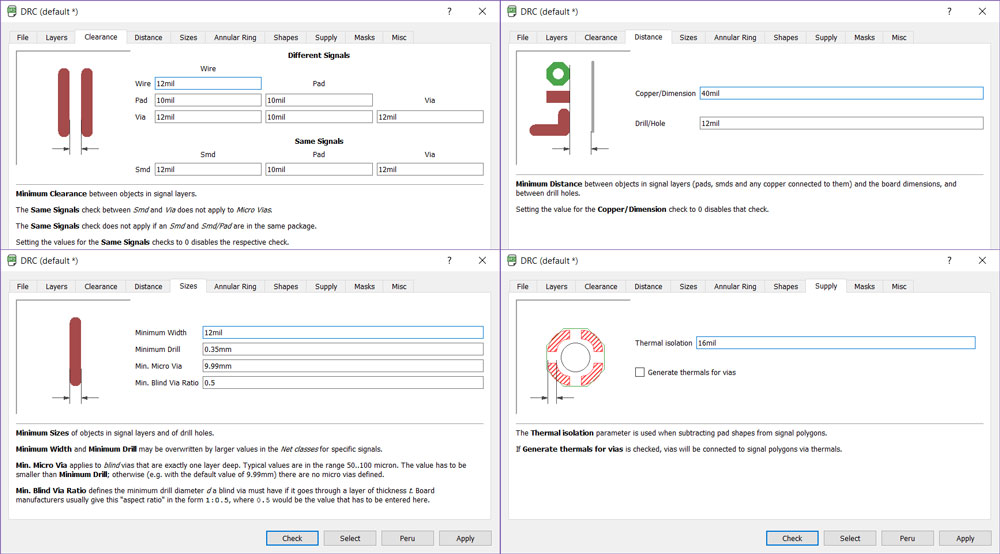
In Eagle Board layout view, first, I did Design Rules Check and did settings as I did in the Week 7. Also, in order to align and move components freely, by navigating in the top bar, I selected Grid -tool, and changed Size to be 5 mils, and Alt to be first 2 mils, and finally 1 mil.
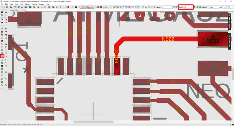
However, when I started to route components in Eagle Board layout I found that 16 mils line width was too much for connecting microcontroller pads and Eagle didn't allow me to route 16 mils lines to ATmega328P.
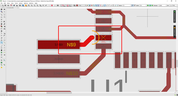
I checked the datasheet to see the measurements and found, that the width of its leg is minimum 0,30 mm. Using Convert Units - Measurement Unit Converter I checked it to be around 11,8 mils so, I considered using 12 mils width in default settings. Thanks to Jari Pakarinen for helping me to figure out this problem with Eagle.
Later on, I changed some of the values to be 10 mils.
It was quite challenging for me and took a very long time to make the board layout with 6 pin headers and one FTDI cable connector, 2 LEDs etc all the small components. First, I placed all of the components to dimension page and grouped the ones belonging together. Here, (!) I faced first challenge with my multi-board-design because Eagle wanted to connect every VCC and GND together even from the separate boards. Fortunately, our local instructor Iván Sánchez Milara suggested me to try naming each of the VCC and GND with differing names so, in Eagle Schematics, using differing components from supply2 -library. This worked perfect and now, I was able to deal with different boards separately but on the same board layout design.
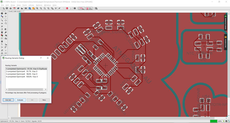
For a start on routing the components, as in the Week 7, I used Autorouter -tool to make the first designs quickly and see, what has to be modified in order to get every connection required connected. In addition to required components, I added four 0 ohm resistors as jumpers to give a route for some routes to cross.
This time I learned also rotating components not only in 90 degrees by right-clicking above the component (or typing e.g. 'rot r90' to command line and then pointing the component), but also degree by degree by right-clicking on the component > Properties > change the 'Angle' in the dialog box. However, when doing routes it was more practical to use minumum 45 degrees angles, othervise the routes winded too much when trying to make a straight line.
Finally, when I got more than 90 % and even 100 % with Autorouter, I started to modify the routes manually to fix the ungrounded areas and also to make the desing nicer. I used "ripup;" command to remove all the wires and start the wiring all over again.
In this phase, I changed the line width to 16 mils for routing manually every line except, when I came close to microcontroller pads I changed the wdth to be 10 mils which I used for connecting the line to the leg.
For checking the connections and the ground around the components, avoiding islands of the non-grounded area, I created a ground layer as documented on the Week 7.
Now, I could use the Ratsnest -tool to make sure that the ground reaches the ground pads of components, and the "ripup gnd" command to remove the visible ground area.
However, here, (!) I faced second challenge with my multi-board-design which was found in testing phase after assembling. When I renamed every boards' GND by differing names, I didn't take into account that because of this, I also have to create separated polygones named separated GND-names to mark each ground and make ground -pads of the components connected to ground. I fixed the design file, which after each board has its own ground and the ground pads are visible.
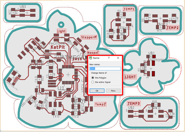
Now, if I want to ripup the ground, I am able to do it separately only for that board that is needed, e.g. "ripup gnd1".
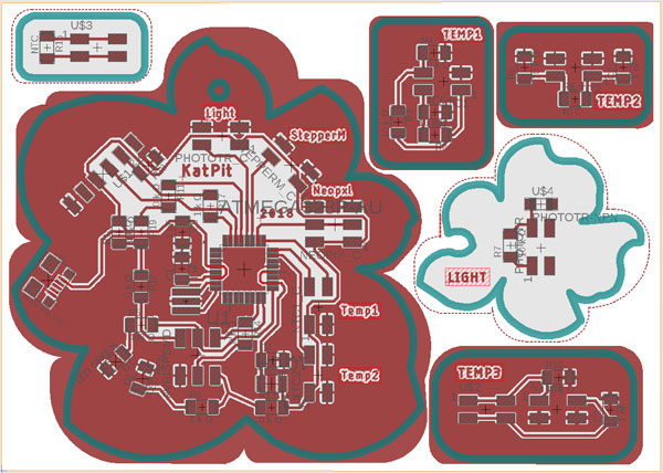
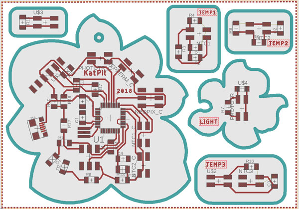
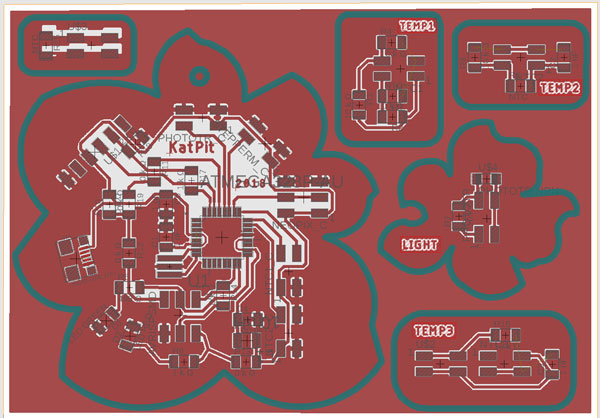
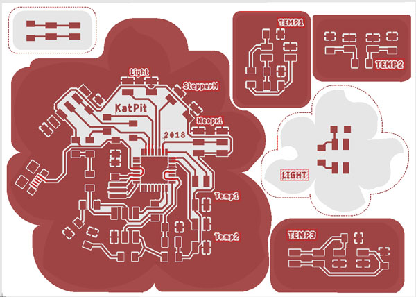
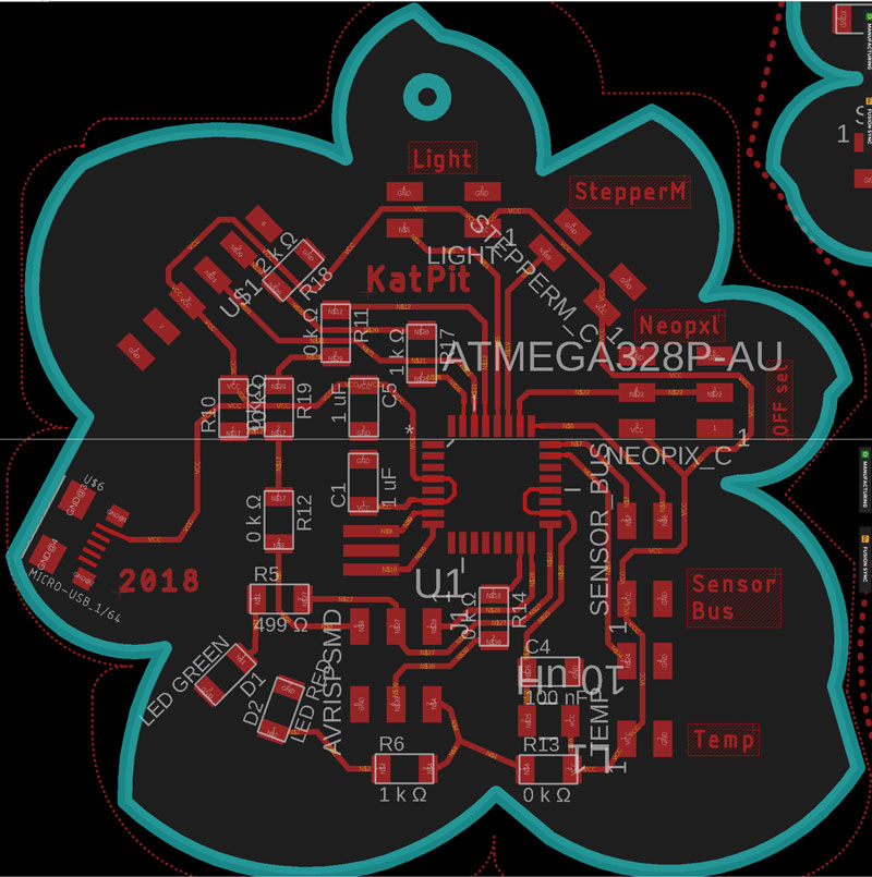
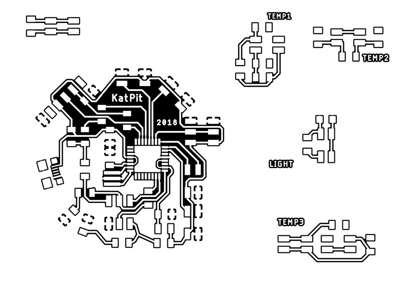
Here is the first finished board layout version of my Flower Board design.
Milling the boards
This time I used Mods to create the .rml -files for milling for the first time.
First, I created a milling file for traces. From the top left corner, by right-clicking the mouse I navigated to: Programs > Open server program > Roland mill SRM-20: PCB and continued as follows:
- Read png // Select png file > Navigate and open your design file
- Roland SRM-20 milling machine // x: 0, y: 0, z: 0 (mm)
- Delete the menu: WebSocket device
- From the top left corner, navigate: Modules > Open server module > File: Save
- Drag and drop the menu next to Roland SRM-20 milling machine -menu
- On Roland SRM-20 milling machine -menu, activate Outputs: File and click Inputs: File (object) on the Save file -menu.
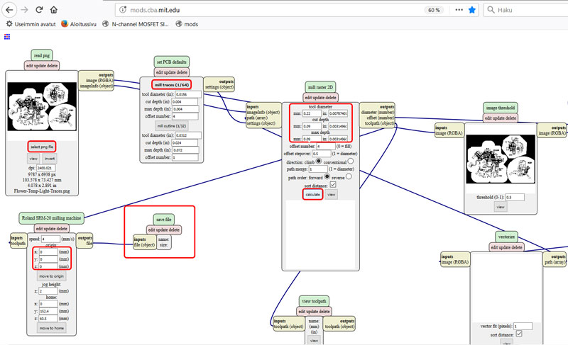
- Set PCB defaults // Activate Mill traces (1/64)
- Mill raster 2D //
- Tool diameter: 0.22 mm
- Cut depth: 0.09 mm
- Max depth: 0.09 mm
- Press Calculate.
Now, Mods generates toolpath for milling traces.
Traces .rml:
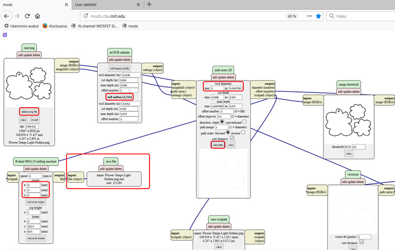
To generate a toolpath for Outline, follow the same steps but instead of selecting Mill traces (1/64), select Mill outline (1/32).
Outline .rml:
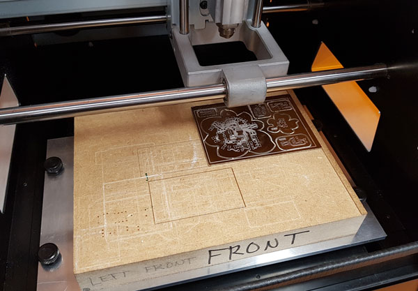
I prepared the Roland SRM-20 milling machine and milled the board based on the process documentation I did on the Week 5. Because of these thin wires I was going to cut and knew that they can be challenging, I paid extra attention on preparing the milling. I cut exactly the piece of PCB I needed, checked that it is not bended with ruler, and taped and placed the PCB as levelled as possible on the milling machine plate.
Some of my fellow students had already tried the cut depth 0.10 mm+ leaving a very thin wires or totally disappeared wires behind. This is why I considered using even less cut depth. In the first phase, for these tiny pads of ATmega328P I decided to use following settings for milling:
- V-shaped milling bit
- Tool diameter 0.2 (mm) and
- Cut depth 0.08 (mm).
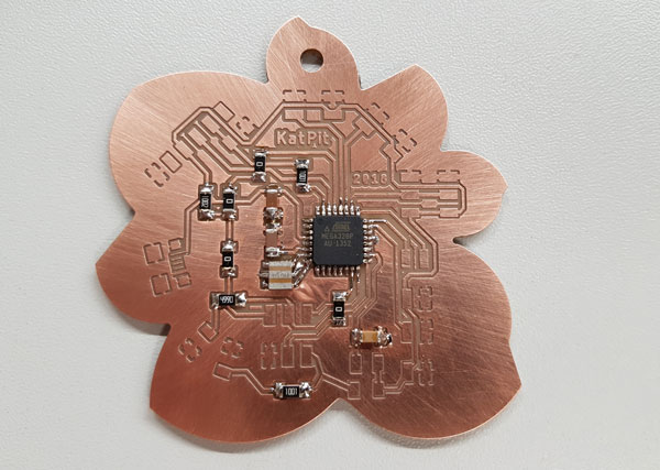
My first cut results turned out to be perfect as seen in the picture below. However, later on during this week most of us including myself faced problems and failed in cut results even with the same settings, and finally, the plate surface of both milling machines' were levelled. In the end, after several failures, also I changed to cut my boards one by one, by splitting the .png file and making several .rml -codes for the boards because it seemed to be impossible to succeed in placing big PCB shield for the three boards at the same time evenly.
Second phase: Cutting board by board and using tool diameter 0,22 and cut depth 0,09 worked fine.
Assembling the boards
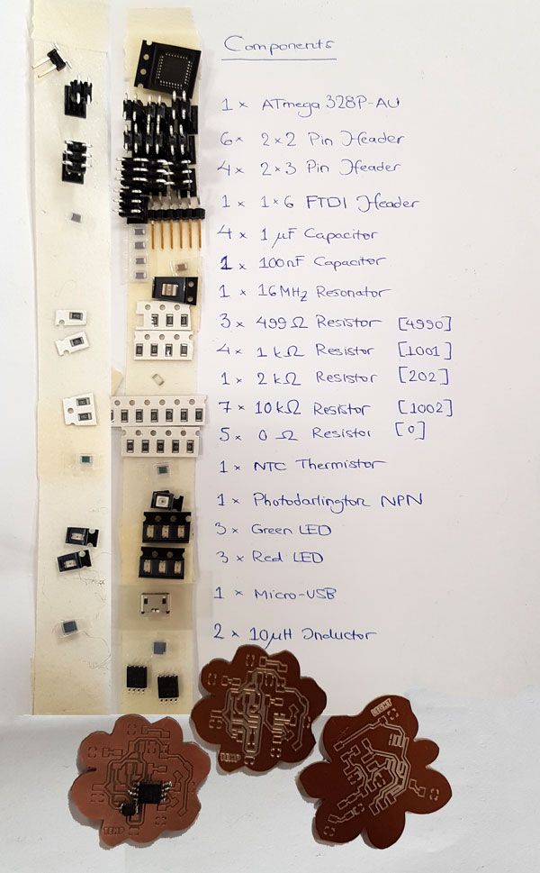
I collected and labeled all the necessary components to a sheet of paper attached by tape, which made easy to recognize the components and see the whole, and pick up the right component during the assembling process. Then, I followed the soldering process documented on the Week 5.
- 1x ATmega328P-AU microcontroller
- 10x 2x2 Pin header // (NTC1_C, NTC1, NTC2_C, NTC2, NTC3, U$2, U$3, PHOTOTR_C, PHOTOTR, STEPPERM_C)
- 2x 2x3 Pin header // (J1, NEOPIX_C)
- 1x FTDI header 1x6 // (AVRISPSMD)
- 1x Micro-USB // External Power
- 2x 1 nF Capacitor // (C2, C3)
- 1x 100 nF Capacitor // (C4)
- 1x 1 uF Capacitor // (C1, C5)
- 1x 16 MHz Resonator // (RESONATOR)
- 1x 499 Ω Resistor [4990] // (R5)
- 2x 1 kΩ Resistor [1001] // (R6, R17)
- 1x 2 kΩ Resistor [202] // (Rxx)
- 7x 10 kΩ Resistor [1002] // (R2, R3, R4, R7, R9, R10, R16)
- 5x 0 Ω Resistor [0] // (R11, R12, R13, R14, R19)
- 1x 100 uH Inductor
- 3x NTC Thermistor // (surface mount temperature sensor) (R1, R8, R15)
- 1x Photodarlington NPN // (U$4)
- 1x Green LED // (D1)
- 1x Red LED // (D2)
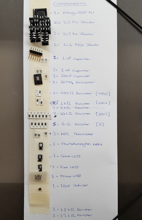
Components of the Flower Board:
- 1x ATmega328P-AU microcontroller
- 4x 2x2 Pin header // (NTC1_C, NTC2_C, PHOTOTR_C, STEPPERM_C)
- 2x 2x3 Pin header // (J1, NEOPIX_C)
- 1x FTDI header 1x6 // (AVRISPSMD)
- 1x Micro-USB // External Power
- 1x 100 nF Capacitor // (C4)
- 1x 1 uF Capacitor // (C1, C5)
- 1x 16 MHz Resonator // (RESONATOR)
- 1x 499 Ω Resistor [4990] // (R5)
- 2x 1 kΩ Resistor [1001] // (R6, R17)
- 1x 2 kΩ Resistor [202] // (R18)
- 1x 10 kΩ Resistor [1002] // (R10)
- 5x 0 Ω Resistor [0] // (R11, R12, R13, R14, R19)
- 1x 100 uH Inductor
- 1x Green LED // (D1)
- 1x Red LED // (D2)
Soldering so tiny pads, that ATmega328P has, was my very first experience:
Components of the first three NTC temperature sensors:
Board 1 // Wheatstone Bridge
- 1x 2x2 Pin header // (NTC1)
- 3x 10 kΩ Resistor [1002] // (R2, R3, R4)
- 1x NTC Thermistor // (R1)
Board 2 // Temperature sensor having only one resistor + NTC
- 1x 2x2 Pin header // (NTC2)
- 1x 1 nF Capacitor // (C2)
- 1x 10 kΩ Resistor [1002] // (R9)
- 1x NTC Thermistor // (R8)
Board 3 // Temperature sensor having only one resistor + NTCt in the separate board
- 3x 2x2 Pin header // (NTC3, U$2, U$3)
- 1x 1 nF Capacitor // (C3)
- 1x 10 kΩ Resistor [1002] // (R16)
- 1x NTC Thermistor // (R15)
We had both temperature sensors, NTC (Negative Temperature Coefficient thermistors) and RTD (Resistive Temperature-sensing Devices/ Detectors), in our stock. In my final project I am going to measure outside temperature so, for my purpopse I chose NTC because according to DigiKey "NTC thermistors are best for precision temperature measurement, while RTDs are best suited to temperature compensation". Moreover:
The NTC thermistor has three modes of operation:
- Resistance vs. Temperature
- Current-over-Time
- Voltage vs. Current
I think, that the first one is suitable in my case: "Resistance over temperature is the most widely used mode, as the thermistor performs precision temperature measurement,
control, and compensation functions. There is no self-heating in this mode. Resistance across the sensor is high. Thermistor housing varies to meet hermetic seal and ruggedness
requirements." [DigiKey]
Components of the NPN light sensor board:
- 1x 2x2 Pin header // (PHOTOTR)
- 1x 10 kΩ Resistor [1002] // (R7)
- 1x Photodarlington NPN // (U$4)
After assembling processes, I tested continuity of wires using multimeter in order to check that connections are fine, and find possible unconnected circuits or short circuits. I started my soldering from the small ones, temperature sensor boards on purpose, to practice a bit before taking the main board on assembling. Here, a couple of short circuits were found due too much soldering iron which then had spread to the ground unintenrionally.
Moreover, I fixed the second challenge with my multi-board-design, and gave some extra tin to the unconnected ground pads and spread the tin over the closed pad lines to the ground copper. This made the sensor boards look not that nice but at least I got the this problem solved quickly to be able to continue to programming.
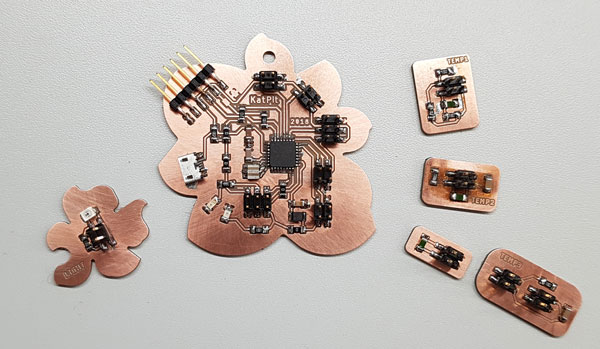
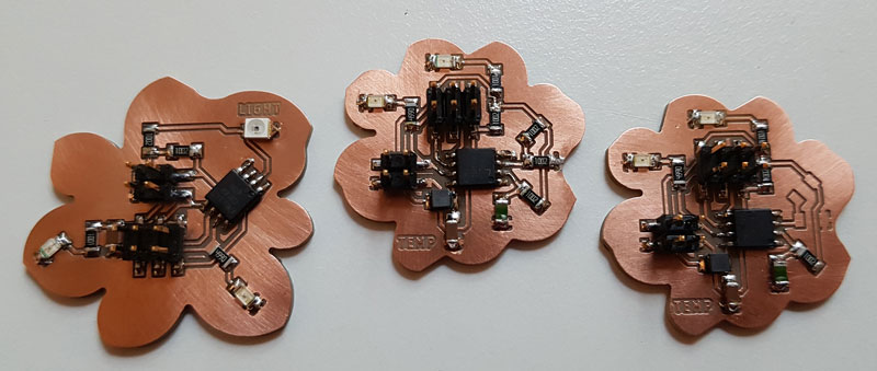
The three fixed temperature sensors:
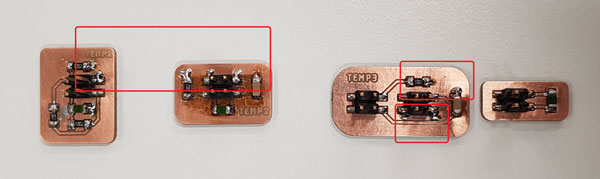
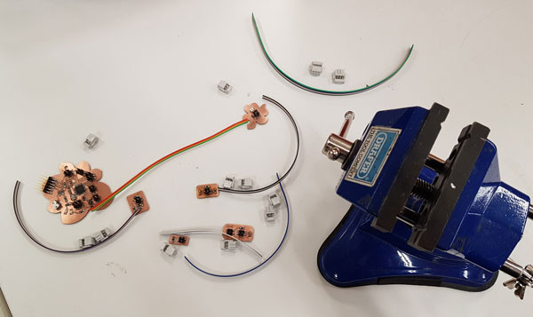
Making cables for my boards:
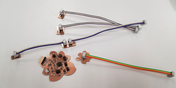
(!) Too bad, what I was noticed only afterward, the last component I decided to add on my board, micro-USB, I had placed in the middle of the petal of the flower so, the USB cable cannot be attached without taking a small piece out of the coupler cover. Next time, I will pay attention on couplers to be sure, that they are placed correctly.
Differential ADC Channel Pairs for Wheatstone Bridge
The issue that came up during the Regional Review meeting was, that I had made a temperature sensor board using the idea of Wheatstone Bridge - over two voltage divider to make the signal more undisturbed, but actually ATmega328P cannot make it. This combination, which needs to measure voltage between two pins requires 2 Differential ADC Channel Pairs, which ATtiny45 has but it ATmega328P doesn't have.
However, even though I cannot use this temperature sensor with this board it seemed, that because of my suitable pin header on the ATmega328P -board, there is a good possibility to make a new sensor board involving ATtiny45 microcontroller, and then use it on the Networking and Communications week to communicate between these two boards! Such a great idea, which for I will give many thanks to Bas Withagen, who noticed me about this issue and possible change!
The Second Phase - Improving the first Designs of the Boards
After realizing, that I cannot make the temperature sensor consisting of the Wheatstone Bridge with ATmega328P, and since Bas anyway suggested to not make separeated sensor boards having only sensor but not a microcontroller on the same board, I decided to make new sensor boards including microcontrollers. At the same time, I fixed my ATmega328P -board.
At this phase, I improved the main board and connections on it. Thanks to suggestion from Antti Mäntyniemi, I decided to turn one of the pin headers, that originally had two signal lines for Wheatstone Bridge, a sensor bus connection for networking .
Next, I disconnected the double VCC line on the pin header aimed at NeoPixel for having OFF set connection for NeoPixels. When connecting the NeoPixel strip only on the right 1x3 pin column, it is not powered through the main board but only the signal and ground are connected. When connecting all 2x3 pins, the strip will be also powered through the same connection. In board layout, I named all the connections to be engraved next to the pin headers. And for sure, I fixed the mistake I made in placing the micro-USB in the previous design.
The final schematic of the ATmega328P Flower -Board:
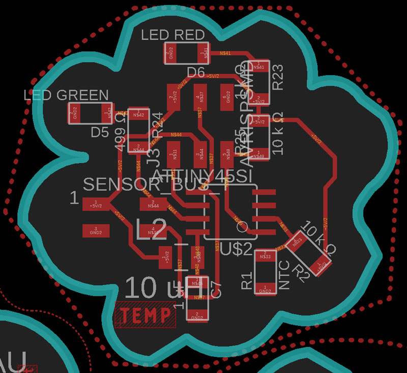
And two dirrerent NTC temperature sensor boards for comparing the results, where the first one has the Wheatstone bridge:
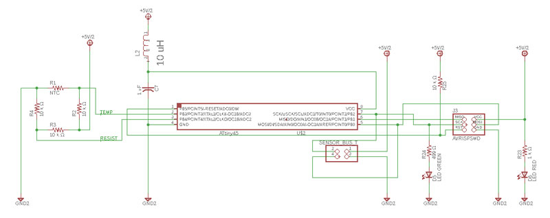
And the second one is using only one same sized resistor in addition to NTC thermistor:
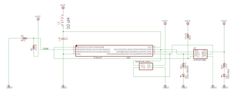
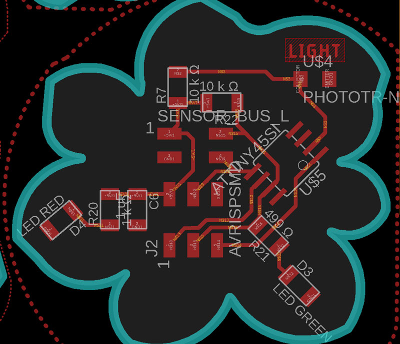
The Phototransistor NPN / Light sensor board:
![]()
The final board layouts of the three boards of the Version 2.
And a little bit more soldering for this week:
Hopefully, I will still have later on time to compare results of these two temperature sensor boards.
Programming the boards
Programming the ATmega328P Flower -board to measure the temperature using NTC thermistor and observing lightness using NPN photodarlington.
I powered my Heart board via FTDI. Then, I navigated in the top bar Tools, and selected correct:
- Board // Arduino/Genuino UNO
- Serial Port // [Check from Device Manager - in my case COM7]
- Programmer // USBtinyISP
Because I was going to program my ATmega328P Flower -board with Arduino IDE for the first time, I did Burn Bootloader for this new microcontroller on my board. I connected my USBtinyISP programmer into my Flower board and hit 'Polta käynnistyslataaja'.
Here are the two setups I prepared for programming:
(1) ATtiny45 Flower -temperature sensor board
FTDI -cable's Power and GND -pins connected to ATtiny45 Flower -board: // for powering the board (red LED is indicating that the board is powered)
ATtiny45 Flower -board connected to USBtinyISP -programmer: // for programming the code that reads the value of the NTC thermistor
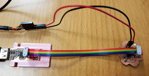
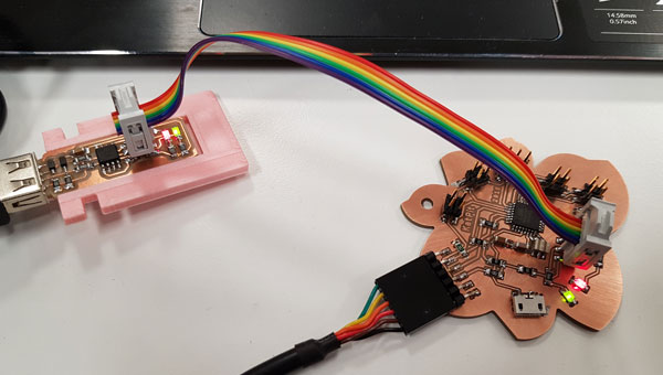
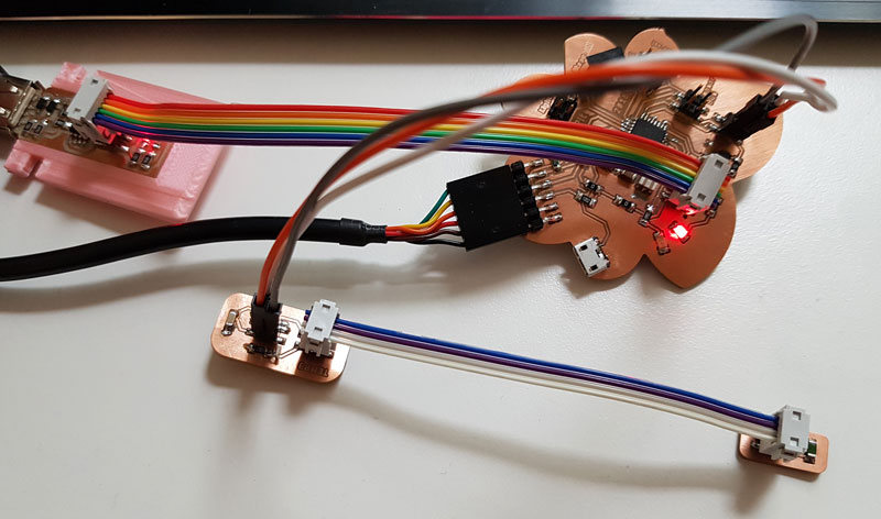
(2) ATmega328P board connected to the plain temperature sensor board (without a microcontroller)
FTDI -cable connected to ATmega328P -board: // for powering the board (red LED is indicating that the board is powered)
ATmega328P -board connected to USBtinyISP -programmer: // for programming the code that reads the NTC thermistor value from the sensor board
Temperature sensor board (without microcontroller) connected to ATmega328P -board: // for getting the varying analog value that NTC thermistor has based on the temperature
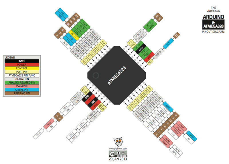
The mapping between Atmega328 ports and Arduino pins obtained from Arduino GEA site goes as follows:
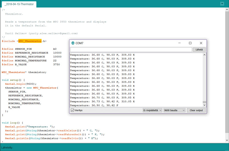
I started on programming the two-piece temperature sensor board number three. At first, for checking if the boards works or not, I just added a new NTC library I found from Arduino IDE libraries: Sketch > Include Library > Manage Libraries, and tried to modify that.
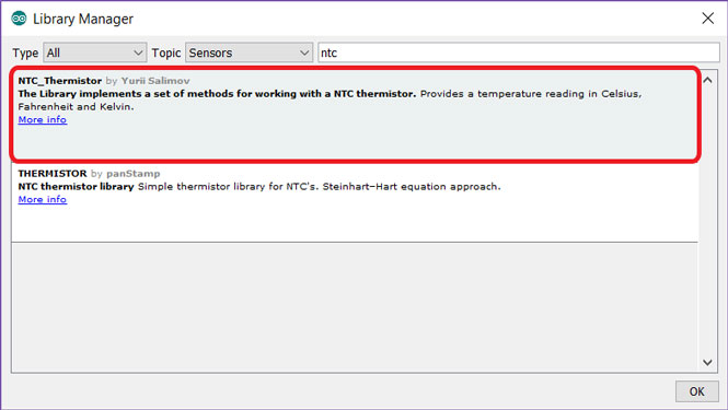
These were the original defined values on the code, that I modified according to the conditions:
  #define SENSOR_PIN             A1
  #define REFERENCE_RESISTANCE   8000
  #define NOMINAL_RESISTANCE     100000
  #define NOMINAL_TEMPERATURE    25
  #define B_VALUE                3950
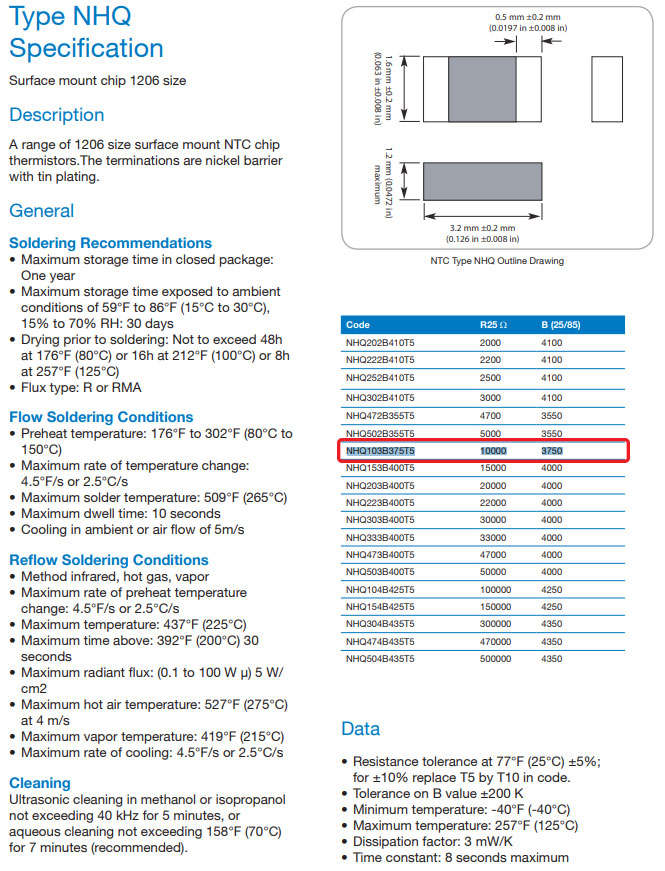
I changed the sensor connection pin to the correct A0, modified the the reference resistanse to 10000, the nominal resistance to 10000, the nominal temperature to 22, and the "B_Value", that I obtained from NTC Type SMD Datasheet, for this NHQ103B375T5 NTC to 3750.
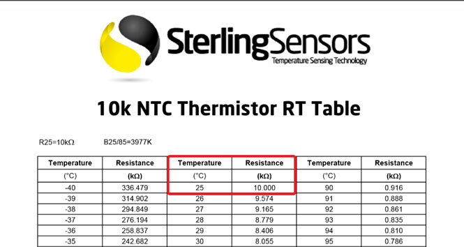
I found the 10k NTC Thermistor RT Table for defining the nominal resistance correct.
By modifying the values, I got some results but nothing real indicating that something was not correct. I was thinking about the difference between reference and nominal resistance and how should I deal with those, but did not finish this at that moment.
Later on, I realised that I was not that far from the solution, but I made some mistakes at that time.
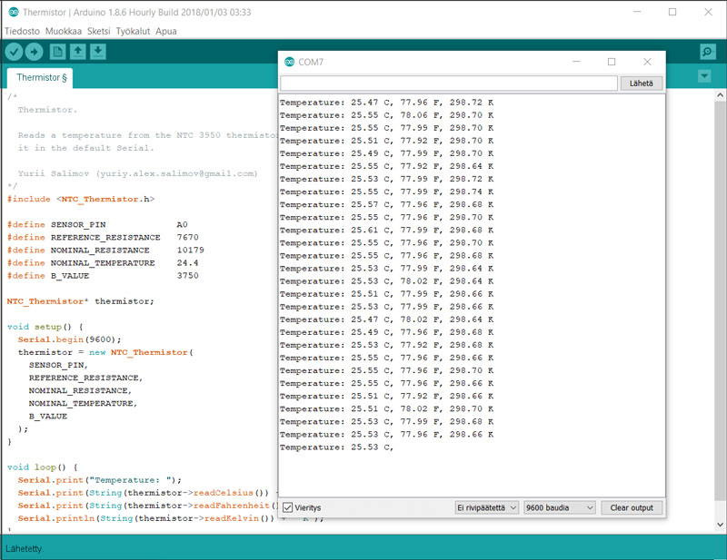
Now, I measured the actual environment temperature with the same NTC sensor board and another working code to be 24.4, and changed the nominal temperature according to that to 24.4 degrees Celsius, the nominal resistance according to that to 10170 (obtained and calculated from the 10k NTC Thermistor RT Table values), and measured the reference resistance over the NTC thermistor at this temperature, I got the code working.
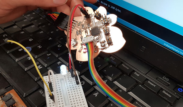
As a one way of figuring out if the problem is either on my board of in the code, we tested my board with the simple LED -code/ breadboard test made by my fellow student Ari Vuokila. The white LED blinked fine so, in general, the board can take some code and perform an action.
Furthermore, after several trials and errors and figuring this out for a some time, Ari noticed that since we bootloaded our microcontrollers to be Arduino UNO, we cannot follow ATmega328P pin mapping but Arduino UNO pin mapping instead. Here is one unambiguous pin mapping I obtained from Bouni and added my pins in the sides of it.
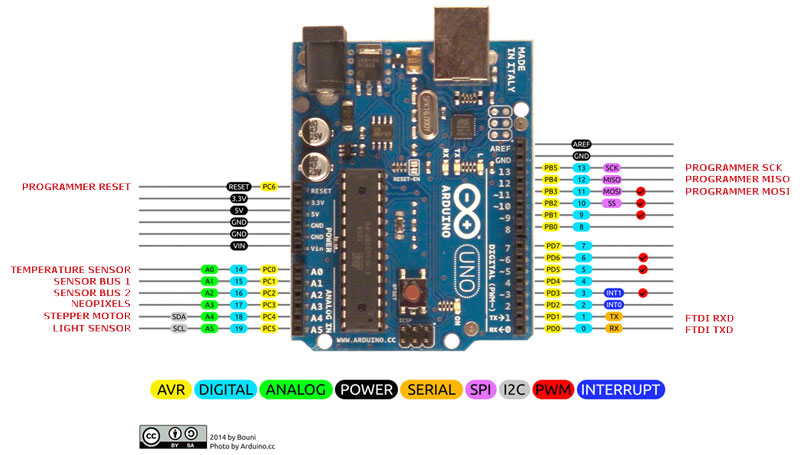
Now, when the pin was changed to be correct it was easier to find out if the code works or not. Finally, I managed to program my temperature sensor board using the calculation Ari has made and writing a simple test code with the help of Iván. Through this step I got some understanding, how to develop the code further for my final project.
Note(!) When sending a program via programmer to programmable board, first of all I have to have the tool Run as Administrator and second, I have to send the program by navigating in the top bar Sketch > Send via programmer or othervise Arduino IDE tries to sent the code via FTDI -cable.
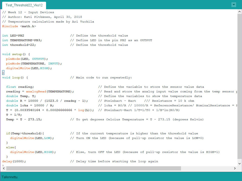
Here is the first test code of my ATtiny45 Flower -temperature sensor board, which basically blinks the LED if the temperature is higher than the threshold value, 22 degrees Celsius.
In the code, I have defined the pins of LED and temperature sensor board, and the threshold value. In void setup I have set the LED as OUTPUT and the temperature sensor as INPUT, and set the LED be OFF in the beginning (the value is HIGH because of pull up resistor).
In void loop I have done the calculation made by Ari, and defined the setting to light up the LED if the current temperature is greater than the threshold value, and else turn the LED OFF.
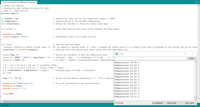
The second code for my ATmega328P Flower -board connected to the plain temperature sensor board (without a microcontroller) is showing the current temperature in the serial monitor. For that, I used Ari's code as a base.
In the beginning of the code, I have defined the variables of int tempPin = A0; and int Temperature:, as well as the float sensorValue;. In the void setup, I have set the temperature sensor to be in input pin pinMode(tempPin, INPUT). In the void loop, I have basically changed to use the variables I defined in the beginning of the code, for reading and storing the analog input value coming from the temp sensor pin the sensorValue = analogRead(tempPin);.
Moreover, I have opened the calculation for my own learning and explained it to myself by commenting the phases next to the code lines. Lastly, I decided to print only the information about temperature to the Serial monitor, and removed the lines that would have print the analog value on it.
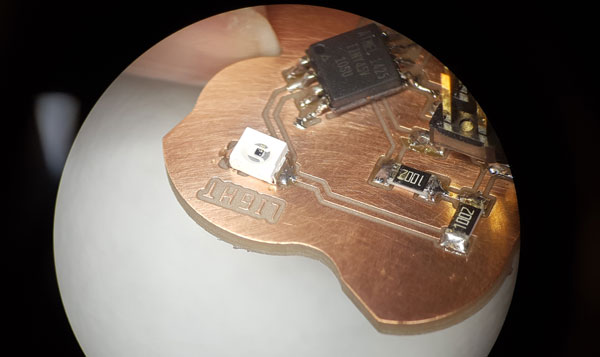
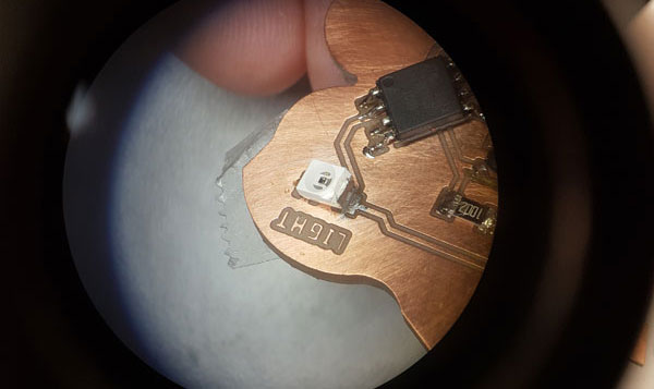
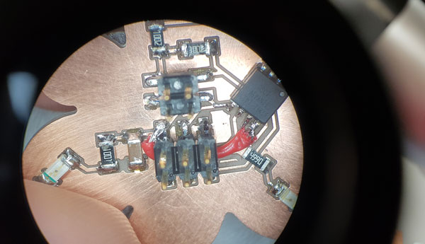
I had problems with my light sensor board on the week, but afterward I managed to solve them. I noticed the problem because the sensor board (ATtiny45) did not accept the bootloader for configuring the fuse bits of the microcontroller to make the board use the right clock source and speed. When I checked the board with a microscope, at first I found, that the NPN component was slightly touching the ground. When I unsoldered it a bit I found the reason: the data pin pad of the NPN sensor was not fully milled which caused it to be connected to the ground and let the tin also reach the ground.
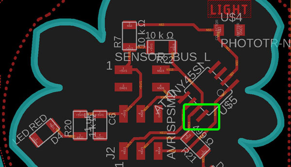
Second, I found that for some reason, the board was missing the power line going from the microcontroller to the components. I checked the Eagle design -file and noticed, that there was no airwires, so I had not seen that this important line was actually missing. I went back and checked all the connections in schematics but was not able to find what caused the unconnection.
I unsoldered the NPN phototransistor from the side that it was touching the ground, and I fixed the not fully-milled pad by a sharp knife, and that way fixed the connection. Further, I soldered an airwire from microcontroller to power line to power the components. Fortunately, it was possible to make it quite short and even made it under the pin header, so it doesn't look that bad. After this, Bootloader was immediately succesfull and I was able to test the programming part as well.
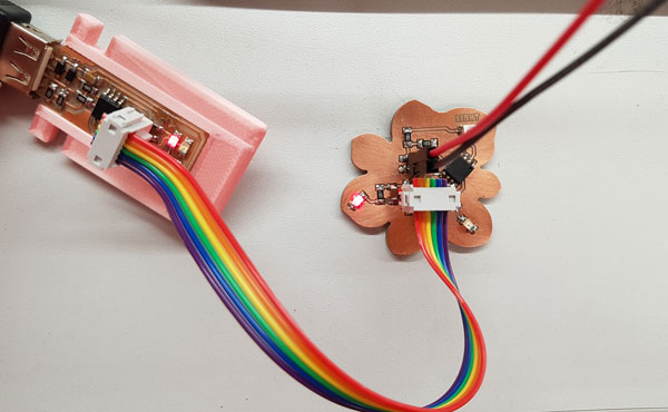
Here is the setup I prepared for programming:
ATtiny45 Flower -light sensor board
FTDI -cable's Power and GND -pins connected to ATtiny45 Flower -board // for powering the board // red LED is indicating that the board is powered
ATtiny45 Flower -board connected to USBtinyISP -programmer // for programming the code that reads the value of the NPN phototransistor
Here is the first test code of my ATtiny45 Flower -light sensor board, which detects the lightness of the environment. If the lightness is higher than the threshold value 200, the board will light up a LED. The code is the mix of this simple example Arduino Light sensor code created by AR Builder and the threshold code above for detecting some cut poin which changes the action and response of the board.
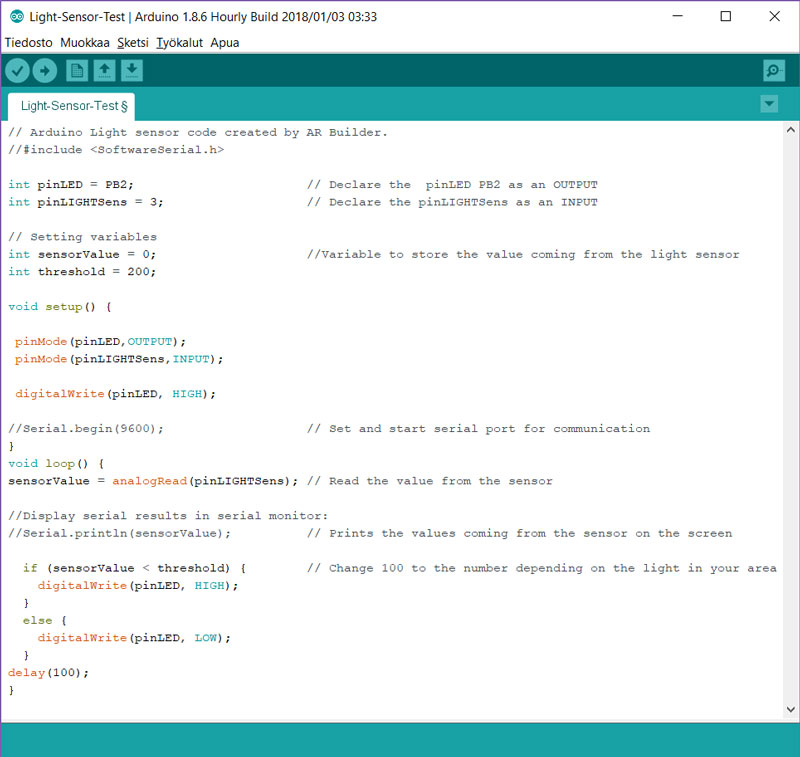
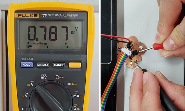
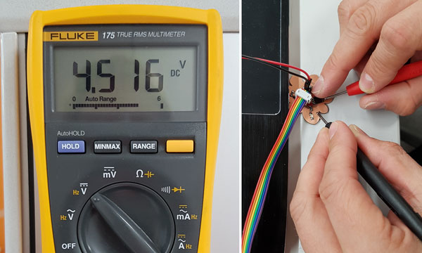
When it is bright, voltage is smaller 0,787 V (measured in electronics building room, working station table). When it is dark, voltage increases - just like in the second picture, where NPN is covered by a finger, and voltage consumption has increased to 4,516 V.
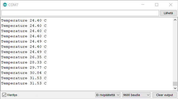
Measuring with the boards
Here, I have measured the environment temperature using NTC temperature sensor (ATmega328 Flower -board connected to the plain temperature sensor board (without a microcontroller)):
// Author: Ari Vuokila
// Modified by Kati Pitkänen on April 30, 2018
// Week 12 - Input Devices
#include <math.h>

int tempPin = A0;                                 // Selects the input pin for the temperature sensor // INPUT
int Temperature;                                  // Initialization of the variable ‘Temperature’
float sensorValue;                                // Define the variable to store the sensor value data

void setup() {                                    // Start this function will after setup finishes and then repeat.

  Serial.begin(9600);
  pinMode(tempPin, INPUT);                        // Temperature sensor is in input pin A0
}

void loop() {                                     // Run over and over again

  //ATmega328P -board converts an analog voltage input (0 - 5V) on tempPin A0 to digital value (0 - 1023)
  //= changes the values from 0-5 to a range 0-1023that corresponds to the voltage the pin is reading

  sensorValue = analogRead(tempPin);              // Read and store the analog input value coming from the temp sensor pin

  double Temp, T;                                 // Define the variables to show the temperature data
  double R = 10000 / (1023.0 / sensorValue - 1);  // Steinhart - Hart    /// Resistance = 10 k ohm     /// (2^10 = 1024)
  double L = 10000 / R;                           // L = R0/R // 10000/R = ReferenceResistance/ NominalResistance = ResistanceInNominalTemperature25oC)

  //T = 1.0/((1.0/(25.0 + 273.15)) + (log(R0/R))/3750))
  //T = 1.0/((1.0/(25.0 + 273.15)) + (log(L))/3750) * log(L))
  T = (0.0033540164 + 0.00026666666 * log(L));    // Steinhart-Hart 1/T=1/T0 + 1/B*ln(R0/R)
  T = 1/T;

  Temp = T - 273.15;                              // To get Celcius degrees Temperature = T - 273.15 (Kelvin degrees)

  Serial.print("Temperature ");                   // To print information to the Serial Monitor
  Serial.print(Temp);
  Serial.println(" C ");

  delay(500);
}
Here are the files of my ATmega328P Flower -board and the sensor boards I designed this week.
- Version 1. Schematic in sch format
- Version 1. Board Layout in brd format
- Version 1. The Traces (changed from png to jpg format when reduced the size)
- Version 1. The Outline (changed from png to jpg format when reduced the size)
- Version 2. Schematic in sch format
- Version 2. Board Layout in brd format
- Version 2. The Traces (changed from png to jpg format when reduced the size)
- Version 2. The Outline (changed from png to jpg format when reduced the size)
- The programming code for Temperature Sensor (Threshold )
- The programming code for Temperature Sensor (Serial Monitor)
- The programming code for Light Sensor (Threshold )