
Kati Pitkänen @ FAB LAB OULU · 2018
© 2018 Kati Pitkänen · Template by Bootstrapious

This work is licensed under a Creative Commons Attribution-NonCommercial-ShareAlike 4.0 International License.
Mechanical Design
Week 16 · [ 2.5.2018 - ]
- Design a machine that includes mechanism + actuation + automation
- Build the mechanical parts and operate it manually
- Document the group project and your individual contribution
This week was great breaking the routines of the previous weeks being based on the group project to build a machine during following two weeks. We wanted to build some three-axes machine moving three dimensionally and decided to create a machine measuring the eveness of the surface. During the first week, we were assigned to focus on building the mechanism of the machine and operating it manually.
It was enjoyable to work together, have and share several ideas, consider, argue and choose the best ideas together, discuss and develop the chosen ideas together, put an effort on your own role for the sake of your group, give and get feedback among the group members, and share and reflect on both failures and successes.
I am very happy with our result of the first week and looking forward to continuing the project on the second week to get our machine automated and running!
MACHINE DESING: FAB KATARI
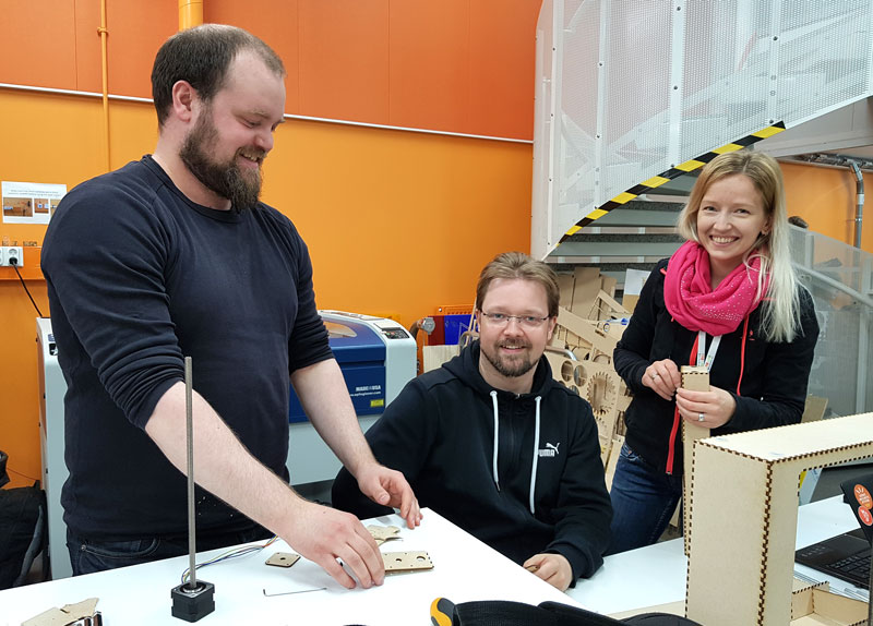
Our local instructor Eino Antikainen facilitated us on the Mechanical Design week to get started. Ari Vuokila, Jari Uusitalo and I found a shared interest in making some three-axes machine moving three dimensionally so, we formed a group. At first we had several ideas in the air, from painting machine to milling machine but finally, according to Eino's suggestion, we decided to build a surface measuring machine that can measure and check how even some surface, such as PCB board, is.
One of my roles was to work on project documentation, so I started it right from the beginning, by taking photos and documenting our workflow, decisions made and both successes and failures all the time during the working phases.
The documentation of the Machine Design -project is here: THE MEASURING MACHINE: FAB KATARI
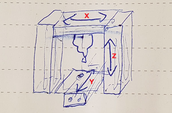
We started from building a shared understanding of the machine and its functioning. For this quick prototype machine we will build a solid measuring head located at Z-axis. We had a couple of ideas for the axes mechanism, how the axes could be located and move the head. One idea was that X- and Y-axes could be located to the bottom part over the plate that the machine is going to measure and then Z-axis would have been in on of the ends moving the measuring head up and down. However, we considered that this type of mechanism requires at least very steady legs and propably also some weight to counterbalance the axis. In the head part, as a measuring tool head, we considered using a mechanism familiar from a ball point pen, where the ball will slide over the surface and measure if the surface is even.
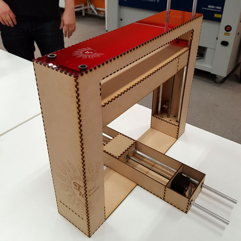
Finally, we decided to use a slightly similar structure to Roland SRM-20 milling machine where the Y- axis will lay on the table having a plate that moves over the axis, and the X- and Z-axes will move the head -part in to two other directions.
In the head part, we ended up creating a structure similar to a ball point pen but changing the function to be a measuring head that moves up and down instead of sliding on the surface, This way, the measuring head will be a kind of button sensor, which moves over the surface by going up and down, and and every time it touches the surface it connects the circuit inside the button and sends information to Arduino about the height of the surface.
Laser Cutting
After deciding and sketching the structure and places of the rods and motors etc together, Ari 3D modelled the machine, and further, Jari unfolded and 2D -designed the parts for laser cutting. I suggested that we could make the cut parts of the machine using two different materials. Also Jari had same thoughts and a similar idea to my final project which is, that we are eager to see the electronics the machine has inside. This led Jari to design the top part of the machine so, that it can hold the gestald boards and cables over the machine and show them nicely through the transparent material.
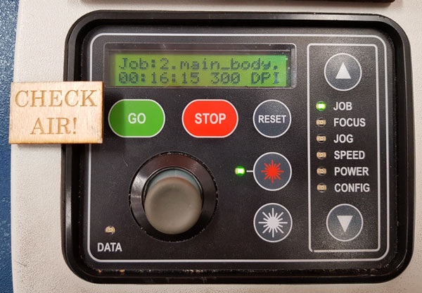
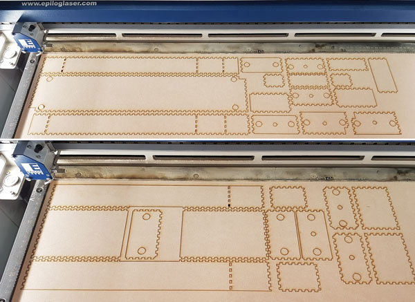
I laser cutted the parts in several phases following the documentation that I have on the Week 4. At first, I did only the vector cutting to see, if the parts work as planned, and decided to add and engrave my graphic designs later on after we have seen, that the mechanism works.
Originally, we wanted to made our machine of plywood (thickness 3 mm) but since we didn't have that one in the lab, I laser cut the parts out of MDF -sheet which thickness is 3mm:
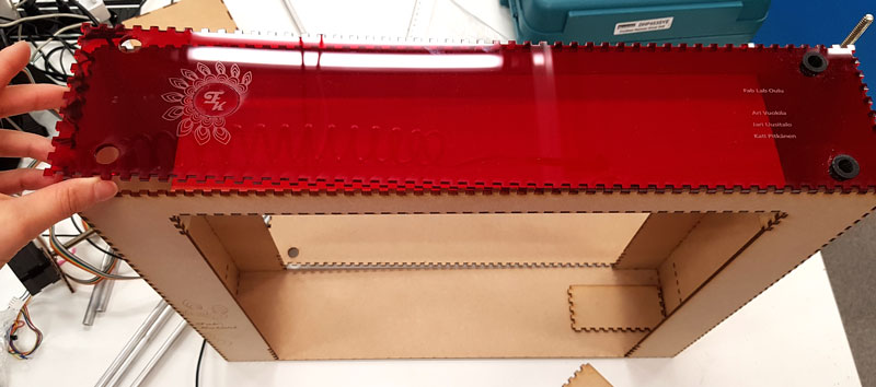
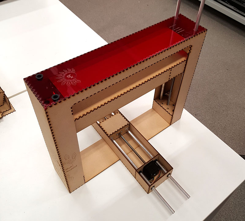
The top of the machine I laser cut out of transparent red acrylic.
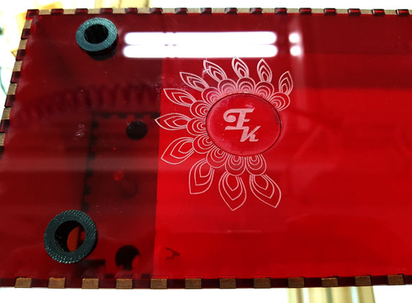
Engraving worked fine otherwise, but one small mistake appeared during the cutting, where the laser cutter cut one circle on top of the machine which it should have been only engraved, and I had fix it by gluing. When checking the thickness of the line in the design file it was 0,12 mm, not 0,02 mm which is the cutting thickness for lines, so it is an unsolved mystery for me why it was cut instead of engraved.
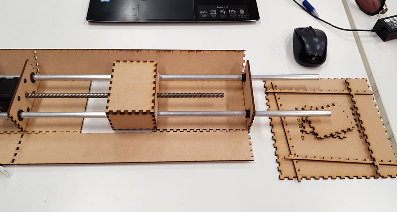
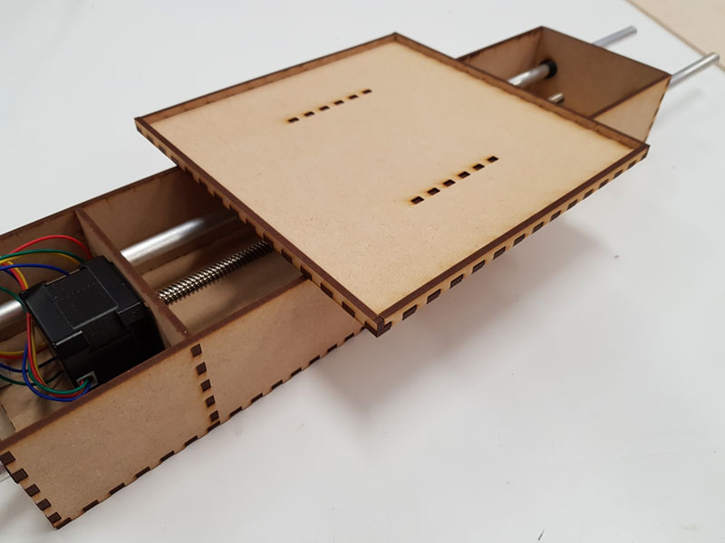
Assembling and 2D Designing
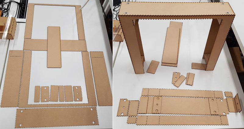
Assembling phase was enjoyable since all parts fit perfect and tight together. I constructed the cut parts to see, how should they be assembled and then we started to assemble them. All of the parts were so accurate that we did not need any glue to support the structure.
After assembling the body of the machine, I designed, laser cut and assembled the plate part of the machine located on the Y-axis.
I continued from Jari's design of the Y-axis and obtained the sledge he had designed. Then, using Inkscape, I modified slightly the side pieces of the sledge by increasing the height of the tooth so, that it was possible to add another sheet of MDF above on top of the sledge. I was aiming to do new tooth with Path > Union -tool, but for some reason it did not work with the original design. It could be, that there were too many grouped objects so, it could not form the union anymore. Consequently, I had to do it manually by creating new tooth and deleting the unnecessary lines.
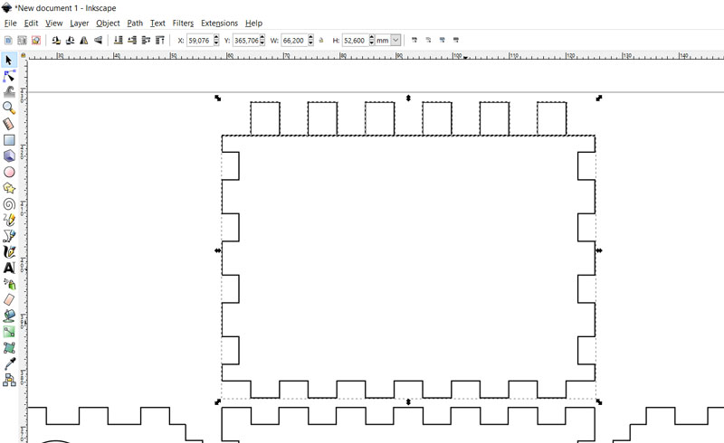
Then, I created a plate to be attached to the tooth in the two rows on a sledge. I wanted to create a thin plate, but to be sturdy, consisting of two layers - a bottom layer made of MDF and a top layer made of acrylic. Moreover, I wanted to create somekind of frames for acrylic. Therefore, I designed first the bottom plate having the edges as a frame for an acrylic plate.
Sketching the plate:
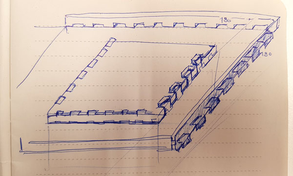
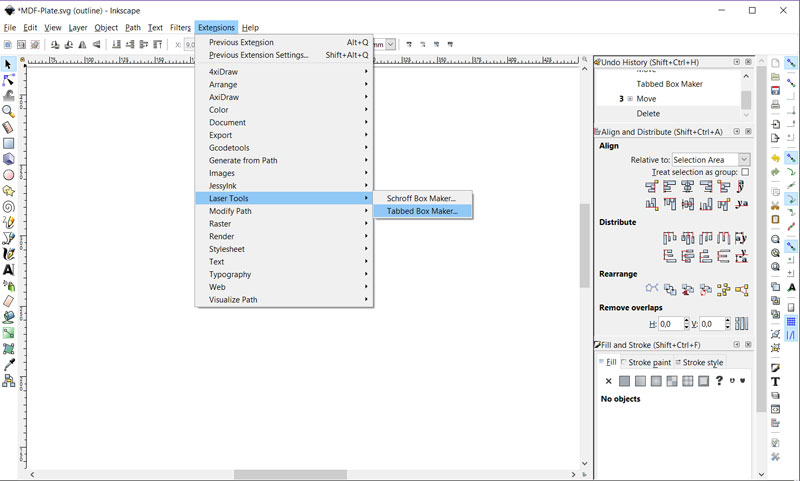
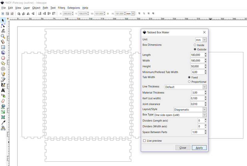
Creating the plate utilizing Inkscape Extensions > Laser Tools > Tabbed Box Maker:
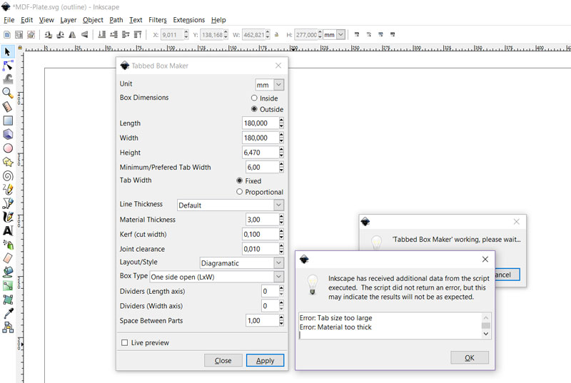
Defining the dimensions of the plate and tabs, box type, and kerf (cut width) to be used for creating a tabbed box. It was not possible to create a very thin box (6,47 mm being the sum of one MDF (3,07 mm) and one acrylic sheet (3,40mm) thickness) with 6 mm tabs, so I had to increase the height of the sides a lot for creating a box and decrease the height manually afterward.
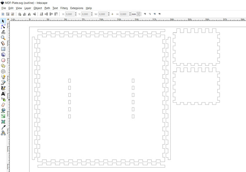
Then, by checking the dimensions of the top part of the sledge, I added holes for tooth coming through the bottom plate. Here is the finished design of the bottom part of the plate to be cut out of MDF:
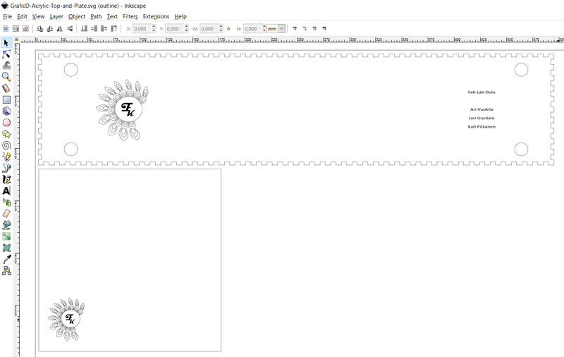
To create the inner, top part of the plate, I measured the dimension of the square inside the created frames of the bottom part. For finishing the design, I added the logo of the machine on the left bottom corner similar to the top part of the machine body. Here is the finished design of the top part of the plate to be cut out of red acrylic (as well as the top of the machine body -part):
To assemble and attach the plate on the Y-axis, I deassembled the Y-axis for changing the side parts of the sledge:
The assembled bottom of the plate located on the Y-axis:
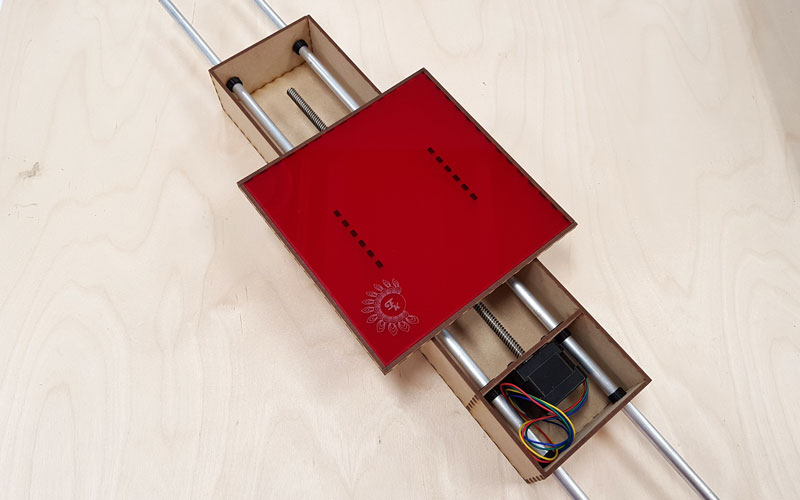
The finished plate with its red top part:
Graphic Designing and Engraving
I wanted to personalize the machine and design graphic objects on the sides of it. First of all, I created a name for our machine using our first names (Kati, Jari, Ari): Fab Katari, which in Finnish can be thought as a nickname for the device that checks something - in this case, the machine checks eveness of the surface.
Secondly, I created a logo for our machine. For that, navigating into a left tool bar, using Draw Bezier curves and straight lines -tool I designed some graphic forms, and with the help of a circle and a an ellipse created using Create circles, ellipses, and arcs -tool, constructed them to a form of a circle. Further, using Create and edit text objects -tool and Magneto -font, I added the name and the machine initials "F K" into the logo.
Graphic designing process of the logo using Inkscape:
![]()
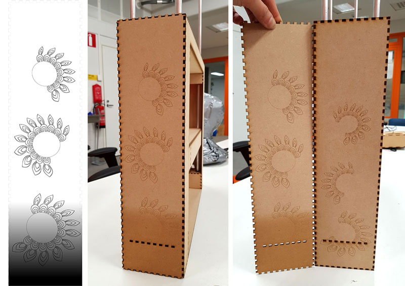
Graphic designs of the main body using Inkscape:
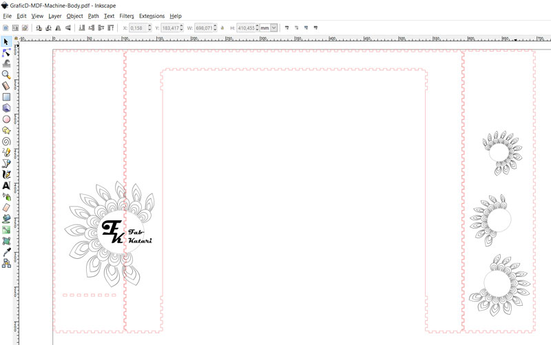
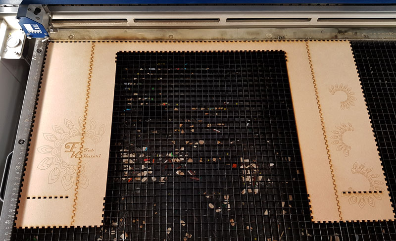
Engraved main body using a laser cutter. I did not have time for making any real 3D -design, so the graphics are simply engraved around the corner by unfolding the parts to be engraved:
The logo engraved on the front corner of the Machine:
![]()
Moreover, I tried a new design engraved on the side of the machine body. However, I did not remeber that MDF is a poor material for engraving gradient graphics. Now I learned, as the picture below indicates, that the result of engraving MDF is monotonous missing all the various tones on the design. However, compared to the first design, we liked more the second one, where the objects are bigger.
Documenting and video-editing
I started to work on the project documentation right from the beginning. It is natural for me to take a lot of snapshots in my everyday life, so I took photos both for helping the documentation as well as for describing the process and presenting the results. I documented our workflow daily, all the decisions made, and both successes and failures, all the time during the working phases.
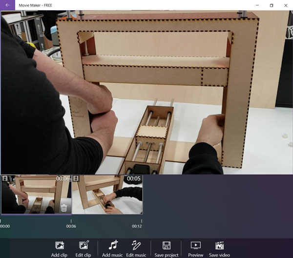
First, I created an initial structure on the website provided by instructors. During the week, I added titles and content alongside of our workflow. I had some challenges in adding a video and rotatable stl model on the website but Ari helped me in those and we got them up and running. The problem with the first video was, that it was made in wmv -format which is not used in any web browser. The second video, about operating the machine manually, which I shot and cutted quickly to 12 seconds using Windows Movie Maker was too big to add on the website. Unfortunately, Microsoft seemed to decrease possibilies to choose the quality of the video on the free version, and the only quality available, HD 720, was way too big. Ari decreased size of the video using Handbrake to render it.
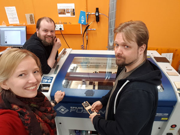
Taking photos during the working phases. Here, after a loooong day, we are waiting for laser cutter to finish engraving the new graphic design of the side of the machine:
The visual appearance of the structure and graphics of the machine after the first week:
The documentation of the project is done by me: THE MEASURING MACHINE: FAB KATARI
Here are the files I produced during this mechanical design week:
- Laser cut file of the Plate in Y-axis in svg format
- Laser cut file of the Plate in Y-axis in pdf format
- Graphic Design for the Machine - Design file in svg format
- Graphic Design of Top and Plate acrylic parts in svg format
- Graphic Design of Top and Plate acrylic parts in pdf format
- Graphic Design of Machine Body MDF parts in svg format
- Graphic Design of Machine Body MDF parts in pdf format
- Video of operating the machine manually