Electronics Design
Link to class: Electronics Design
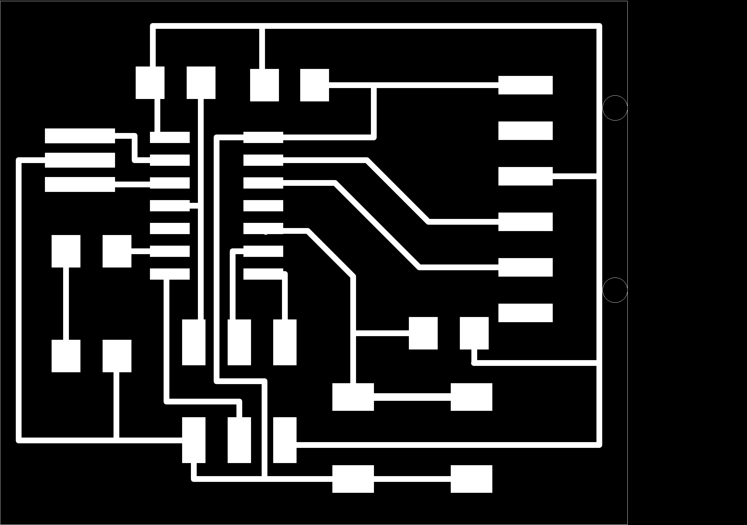
The assignment for this week was to redraw the echo hello-world board, add (at least) a button and LED (with current-limiting resistor), check the design rules, and make it.
Step one: Working with EAGLE
I downloaded the Eagle 5.9 version, according to Henry's advice, so everyone uses the same version of eagle and we don't have problems in the future. We also had a special class by Roberto Delgado from Fab Academy 2012, who was kind and pacient enough to teach us some of his knowledge.We learned how circuits worked and how to use Eagle interface, how to import libraries and other things that would help us along the way. Personally I also consulted Ana Kaziunas' tutorial on Eagle which was very helpfull on understanding the many aspects of the Attiny microcontroller, and how this will play an important role on my final project.
After you're done with Eagle, next step is using the Fab Modules.
Go to Ubuntu, then clic on the TERMINAL
>sudo bash
>fab
A window opens where you need to select the type of file you're going to use, in this case: .PNG
Then, you need to select the type of milling machine, in this case: ROLAND MODELA. rml
In the next window:
On top, for traces change the value to: mill traces (1/64). For cutting the board: cutting (1/32)
FROM .PNG:
TO: PATH Then clic on MAKE PATH. The values that need to change:
TO .RML
After this is done, clic on MAKE .RML
BEFORE doing anything, you need to place the mill where your copper board is. We use double tape to paste the board to the base of the Modela. After you've placed it, you need to do as follows on the MODELA:
If you look on the modela, there are values on the sides (10,20,30...). This indicates the coordinates. You need to place your board on this coordinates and then write this on the X,Y of the fab modules to tell the mill where it will begin. After this: Clic on SEND IT! And hope for the best.
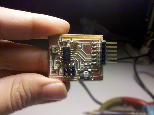
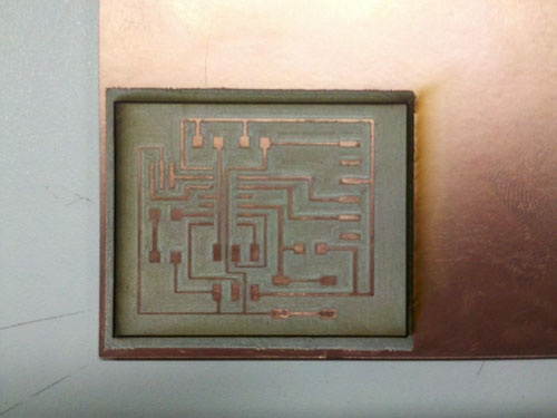
Step two: Making the board, Components and Weldering
After playing with Eagle for a while, I got much more comfortable with the interface and following the tutorial I described earlier, I finally got to make my board. Now I needed to mill it on the Modela.
Using a NEW MILL:
For this assignment we got to test the new mill bought by Felix, with an adaptation made by Toshiro. My first board is actually the FIRST board made with this mill. My impression comparing the 4 boards I had to make is:
Recomendation: Use a different shape of mill and make more tests. I made 4 attempts until I finally got a board that I could use. What I can get out of this experience is that I learned how to use the Modela and making my own boards, which I believe was the purpose of this assignment. What I can see for the future is that I want to keep exploring the options of the Attiny microcontroller to incorporate it on my final project, since I want to use led and lightning sensors.