

Output Devices
This week's assignment was to add an output device to a microcontroller board and program it to do something. I decided to work on LED to learn from this for my final assignment that will involve the use of a lot of them. So I worked on the LED array board.
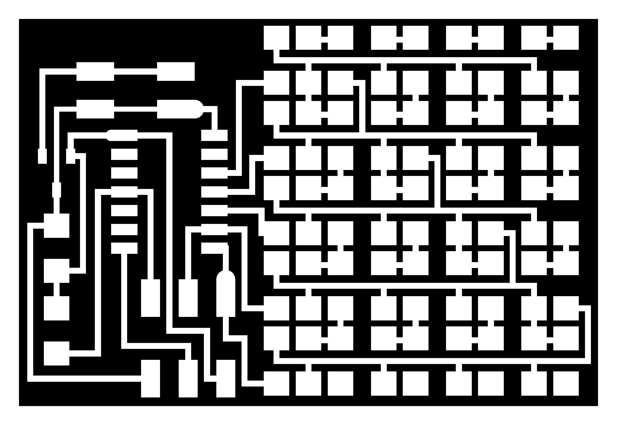
Step ONE: Soldering the LED array
I did not encounter many problems with soldering. It's been a long way since the FabISP fiasco, so I learned a lot and also followed the Ana Kaziunas tutorial, wich led me to Astrid Lubsen's page with good advice on soldering and overall the entire assignment. A very good advice on Astrid's page was to put some little drops of lead on the part of the board to fill in with LEDs and resistors.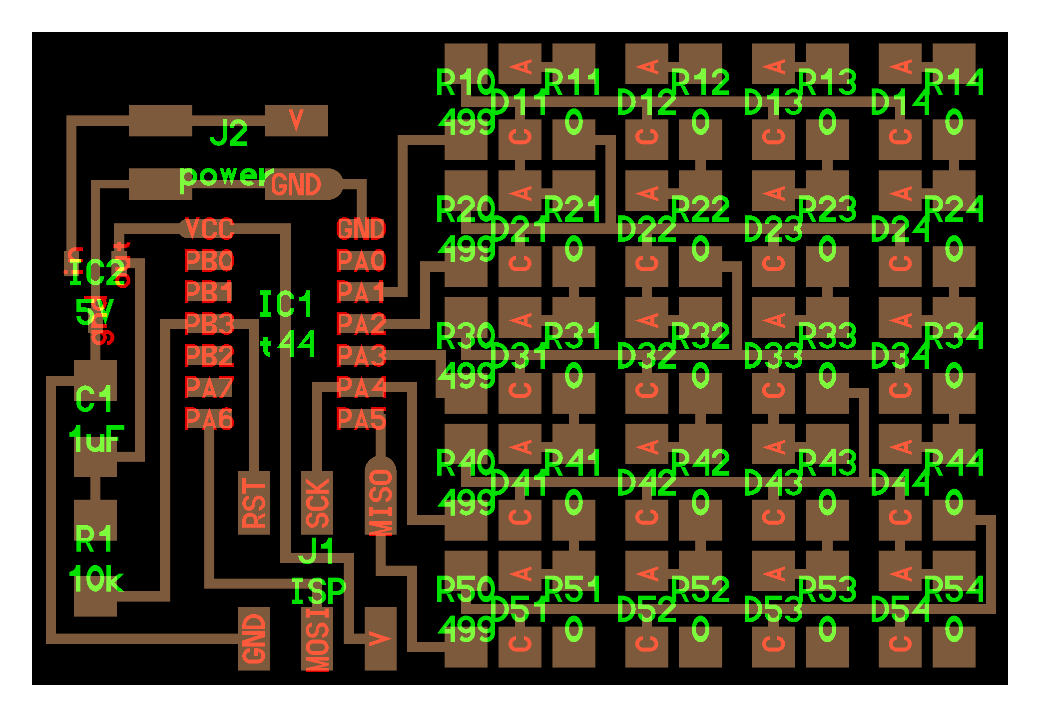
Follow this steps and you'll have a happy weldering:
Step TWO: Programming the board
In this part I encounter some trouble. First of all, the Fab Lab Lima was re-arranged and a lot of machines where transported to other places, and the computer we used for programming was not available all the time. After downloading all the libraries to make it work, I finally connected my board to the computer and program it through the FabIsp. If you don't know where to find this libraries, you can check my tutorial for FabIsp or Henry Medina's from Fab Lab Lima.This is the C file
This is the Makefile file
Then when I connected the battery to my board I was mislead by the examples I've found online and didn't pluged it in the way it was supposed to. I guess every board is different, even if you do it exactly the same as the tutorials. When I plugged the battery it heated excesively, so I knew something had to be wrong, but I didn't knew what. Satoshi help me on this one and connected it the right way.
After this, I finally connected the board with the FabIsp and then to the computer.
sudo make -f hello.array.44.make program-usbtiny
And magic happened...
© vane_montezuma. All rights reserved.
Design by TEMPLATED.