
Mechanical Design & Machine Design
Link to class: Mechanical Design & Machine Design
This week's assignment was to design or modify a machine, making as many of the components as possible, document the group project and your individual contribution make the passive parts and operate it manually.
We team up and decided to make a Portable CNC. My contribution to the group is not on the mechanical and programming part of it, but I wanted to contribute with ideas and make a guide through the making of the machine. Since we are just 4 people in the fab academy right now, we decided to make the assignment all together. My part of the work was to investigate on the different machines that could be used as an example and also about the "head" of the final machine.
I found an awesome paper by Ilan Ellison Moyer on Rapid Prototyping of Rapid Prototyping Machines.
With this i got a much bigger understanding on how a machine works and what was exactly what we need to do. My teammates all have engineer degrees. As an architect is a challenge to understand the funcionality of the machines. One thing is to understand how to use them, and another completely different is making one. Doing research on the web I found the Fab@Home project, which broadened my knowledge even further. Most of this projects are driven by the need of having machines at a low cost and available for everyone. Sadly the page is not updated and I couldn't see much more on the models from fab@home. The one thing that has kept on moving is the community part of the page. This was also a goal for the assignment: to make a machine with the things we had at Fab Lab Lima withouth going out of our way on the cost of the project.
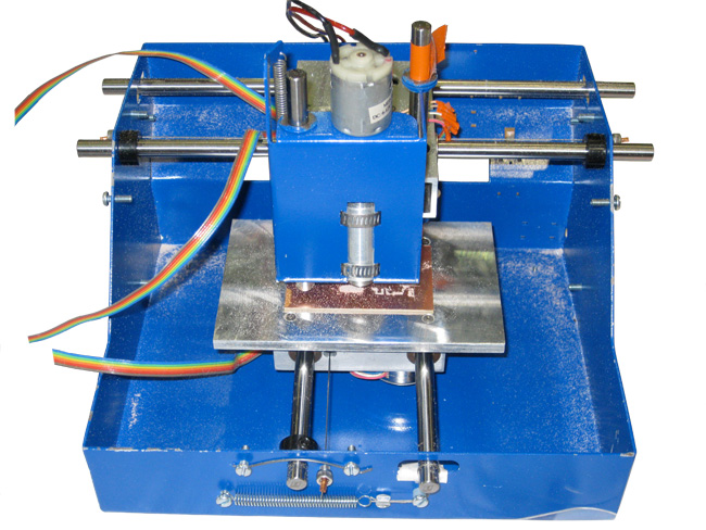
I know that this examples are about 3d printers, but what this assignment has helped me understand is that the principle of this machines is pretty much the same: The use of 3 or 5 axis, depending of the machine you are building, and the type of tool head that is implemented, like a laser head for the laser machine, a mill for the modela, or an end mill in the case of the CNC machine. By studying this examples I got to understand much better the parts of them and how this was going to work, at a mechanical level. One interesting thing about the Low Cost PCB Mill is that the tool head moves on the X axis, meanwhile the table is moving on the Y axis, resulting in a reduction of the size of the machine, which was also something that could be useful regarding the design of our own machine. In most of the machine I've seen on the Fab Lab Lima and also in other labs, the tool head moves on a X, Y, Z axis.
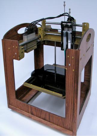
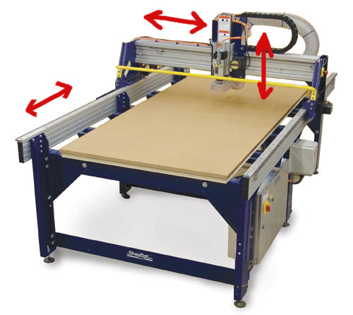
The movement of the Shopbot is more like the image we can see below, of a Fabmate personal fabricator, with a gantry that allows this X,Y,Z movement.
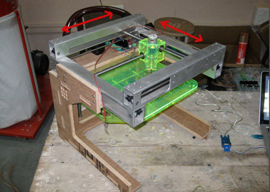
After this example, I also found the Pop Fab, which was in my opinion one of the best options, because the tool head stays put, while the table is the one actually moving.
PopFab Episode 1 - Introduction from Ilan Moyer on Vimeo.
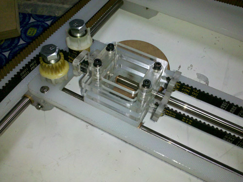
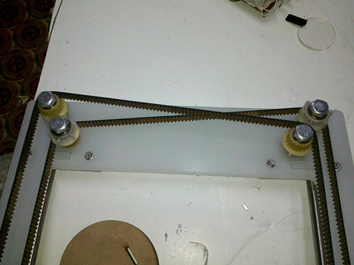
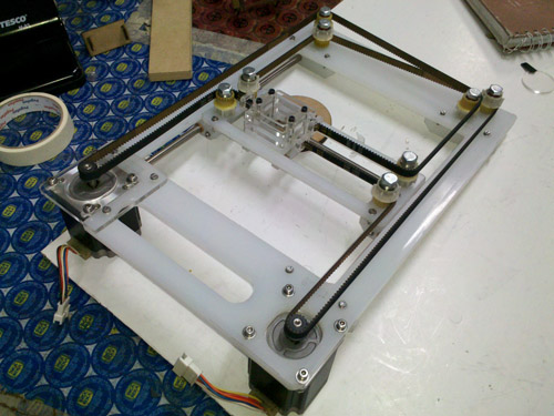
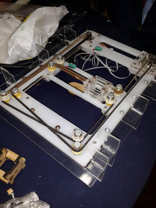
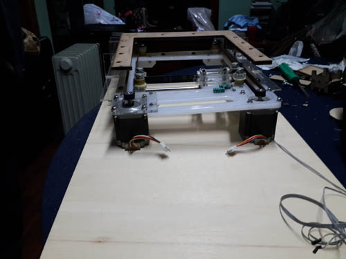
The project for the machine integrates all of this ideas. This is the base of the whole machine, an XY axis movement gantry. The white material that is the base of this is actually a cutting board used for slicing food. But since the material is economically affordable and maneable, it was used for making this part. Also the motors and the belt for the motor mechanisn come from spare parts from an old copying machine.
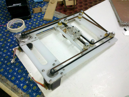
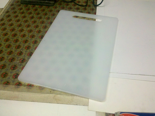
This is the cutting board that was used for the base of the project. It is made of a hard plastic and as I said it before, it is affordable and very cheap. It was cut is the Shopbot like any other piece of wood.
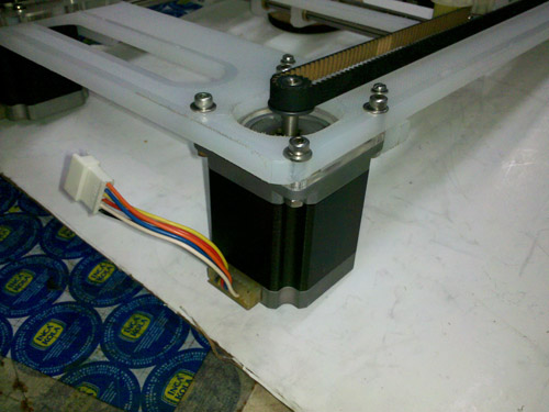
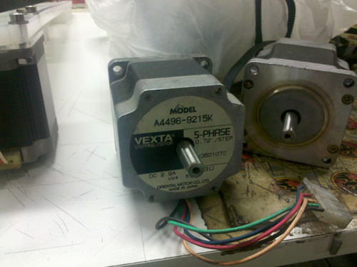
I found interesting literature on the subjetc here: http://ftp.cnchungary.com/Varsanyi_Peter/CNC%20vezerles%20-%20PLC/50VEXTASTEP.pdf. The motors used where 5 PHASE, 0.72"/STEP, AX060107C, DC 2.9A, 0.23Ω, SP8 18336,VEXTA. This are commonly used by people who want to make a DIY CNC machine, as I've seen in many forums asking for guidance.
What I believe was made is a good exploration for a machine that was never finished. After this assignment was over, some of the group members decided to make a machine based on this and the Roland Modela. This machine was forgotten and finally after many conversations the "head" of the machine was replaced by pencil and made drawings in a paper with an interface developed by Cristian Cisneros. I believe the size and the motors are over dimensioned for a machine that only draws with a pencil. This is because the machine was never planned. I believe that for a two week assignment we should have thought on a better solution and a more creative one. As in Ana Kaziuna's tutorial for machine design, the idea of using a pencil was made in a much more efficient way and worked perfectly. Our machine lacks in design and also in functionality.
MY CONTRIBUTION:
I decided to make a pantograph accesory for the machine. Inspired by the idea of the pencil attached to the "head" fo the machine, I decided to make an improvement by adapting a pantograph to the pencil.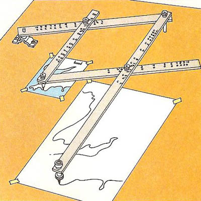
What is a Pantograph? Is an accesory used to reproduce a drawing twice or triple its size. It's very easy to use and I thought it would make the machine significantly more usefull to somebody that wan't to reproduce a computer generated pattern on a piece of paper.
Challenges: The actual pantograph is just made of pieces of wood and has never been adapted to a machine like this before. I had to be very carefull with the length of the movement of its parts and how this would be affected by the size of the board and the motors.
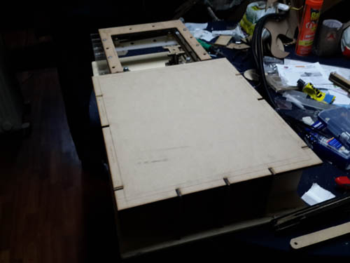
Solution: I decided to make not only the accesory but build an entire base for the machine to stand on, give it some stability that was much needed and also, create a place to comfortably place a piece of paper to make the drawing.
1. Initial Idea:
My first idea was based of some images I got from different websites on how to make your own pantograph. I'll explain myself better with some drawings and sketches: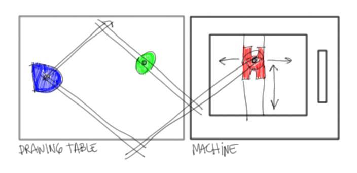
The blue point has to be steady, meaning is doesn't have to move. The green point is where the pencil goes. And the red "H" is the head of the machine. My first idea was this: The red "h" moves in X,Y direction, meanwhile, the green point where the pencil goes is moving along, reproducing a smaller version of the path that the red "h" goes on.
The problem with this is that a pantograph actually makes a BIGGER drawing. My first idea was hanging to much on the thought that I might damage the machine by adding things ON it. But after I built my addition, I realised I could make it so much better.
2. My Idea vs. 2.0
I changed the order of things: The blue steady point now is located next to the machine. The point where the pencil was is now with the red "h" and the green point is on the far end. When the red "h" moves, the green point draws a bigger image.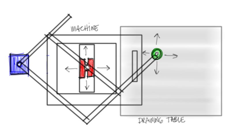
3. Plan in action...
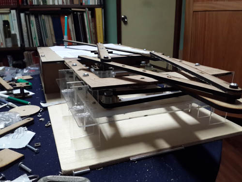
Well, then it was all about making things fit in the right place. As always, I found some issues I had to resolve on the go. At first I was going to make it all acrylic, but I find out that it wasn't the best material because it broke a lot. Since in the lab we only got the 3 mm acrylic available (6mm would have been better), I had to resolve the matter and make it on 6mm MDF. This was great because it gave stability to everything.Also, the distance between the blue steady point and the table had to vary a lot to fit. And the lenght of the arms had to vary by 5 cms to actually draw correctly on the board.
Other issues where on the stability of the pantograph itself. I had to make it taller to separate it from the base, so it would have more space to move freely.
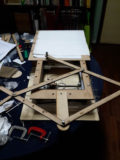
This was my original idea. It had to evolve because the acrylic was to delicate for handling and because at first I thought that the base where the pencil was going to draw was going to be on the table, then I realise I had to lift it up.
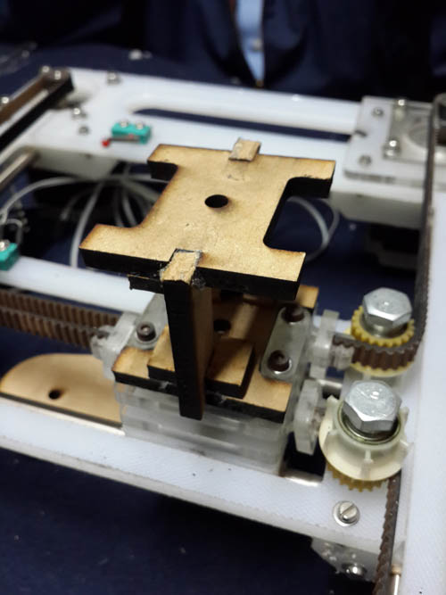
In the design process I figure out it was better to make my contribution on top of the machine, because I didn't want to mess up all the work done. I design a pedestal to go over the head to lift it up.
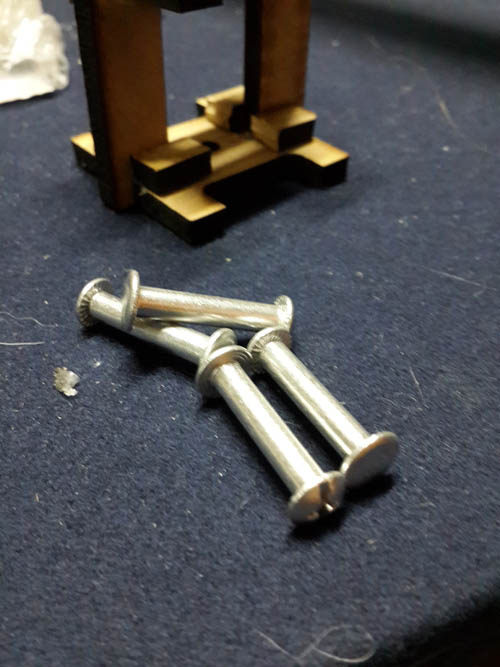
Over the course of the academy i found out that this type of nails are the best for making mechanisms axis, because they are light (made of aluminum), easy to use, come in different sizes and are relatively cheap. I used them here and also in my final project to allow the mechanism to flow easily.
This is my first sketch, which actually didn't work, because instead of drawing bigger images, I was reducing them, which wasn't what I wanted.
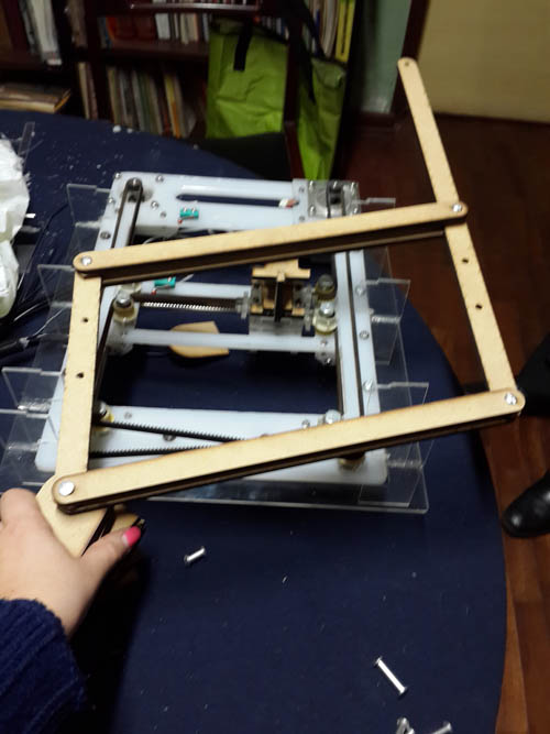
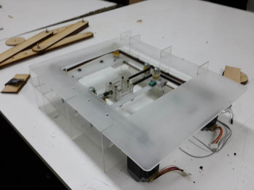
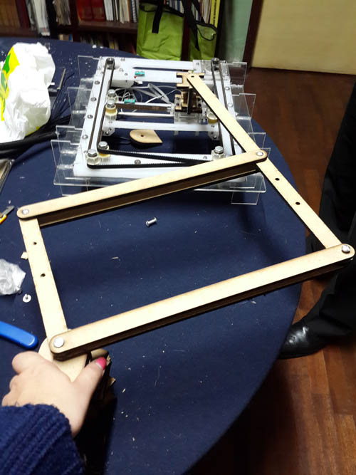
This was the correct and final position. Now it was time to build everything according to this...(Sorry about the mess...)
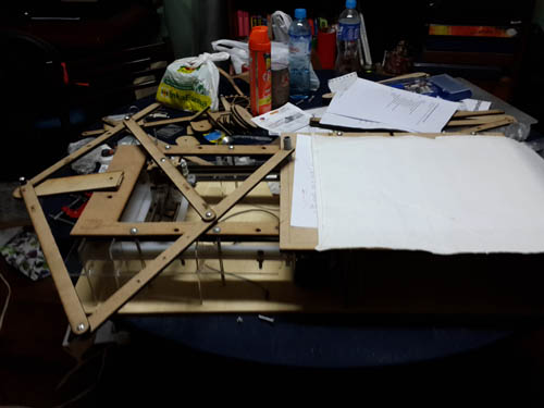
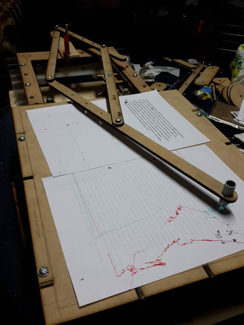
This is the final product. I might say this gives a better understanding on what I intended to do. I managed to make it work manually and it reproduced the path that the machine did on the piece of paper you see right there.
FINAL CONCLUSIONS OF MY CONTRIBUTION:
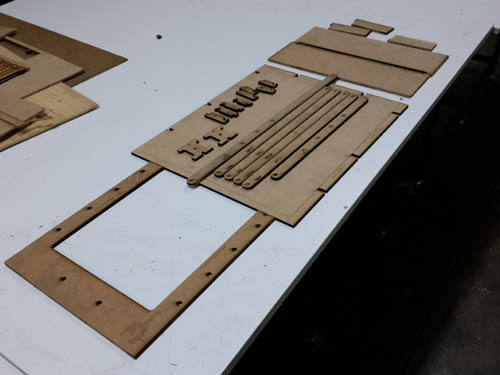
I believe this gives a lot of possibilities for a new kind of machine for the fab lab. The pencil can be easily replaces with any kind of tool, like a drill or a milling machine. I think it could become a mini-shopbot for much more precision tasks.Materials need to be improved. I would like to see it on a 6mm acrylic, because I think it would look much more professional and clean. The MDF is good for a first sketch, but it shouldn't be the final material of any machine, because it to rough. This are the files to laser cut the base (right clic and download)
This are the files to laser cut the pantograph (right clic and download)