Input devices
1_ UNDERSTAND HOW THE ADC " Analog to Digital Converter" WORKS.
What it does is to convert " real values" into binary values 0,1.
In this case we are working with 0 volts and 5 volts.
INPUT DEVICES____VOLTAGE OUTPUT__PIN ADC___VALUE
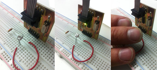
2_ MEASURE LIGHT
Using a LDR Sensor, I have configured the hello world board to be able to read the LDR Sensor using one of the FTDI conectors( pins).
Then I have used Arduino to program the pins and also to read the analog value.( Arduino does not need the user to configured the analog values as an input)
3_ CODE
/*
The LED blinks with different intensity when we apply different types of light.

Considering 1 as No light at all, the blink will be almost none.
 */

void setup() {
  // initialize the led pin as an output.
  // Pin 8 has an LED connected on most Arduino boards:
  pinMode(8, OUTPUT);
  // Pin 7 (PA3) is our entrada
  pinMode(7, INPUT);
}

void loop()
{
  int entrada;
  int an;

  // reading the digital value in the pin number 7
  entrada = digitalRead(7);

  //reading the sensor analog value
  an = analogRead(1);


  // if the entry has value = 0 (botton not pressed) blinking (the block between {}will execute)
  if (entrada == LOW)
  {
    digitalWrite(8, HIGH);   // set the LED on
    delay(an);              // wait for a second
    digitalWrite(8, LOW);    // set the LED off
    delay(an);  // wait for a second
  }
  else {  // if not, the LED will be active and turn on
    digitalWrite(8, HIGH);
  }
}
4_ IMAGES
5_FINAL PROYECT
For the final project i will be using 2 types of sensors:
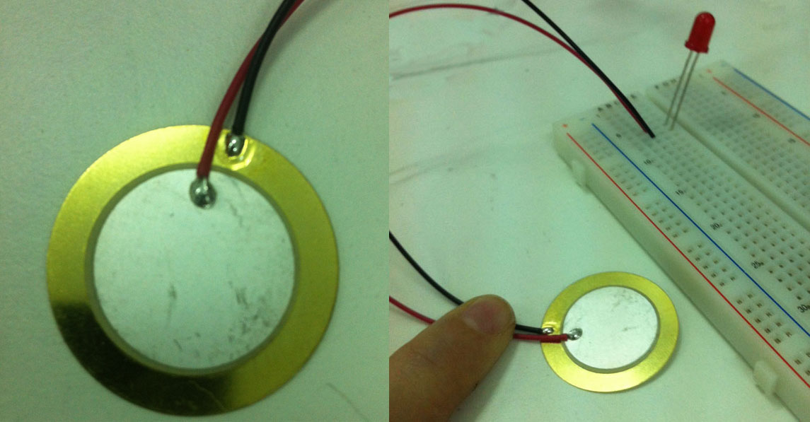
1_PIEZO _" 2 materials, when we applied electricity they vibrate. And also if we touch it, he returns electricity (voltage).
2_MOTION SENSOR.

In this picture we can see how the piezo is connected to a RED LED,
And when we touched it the LED slightly light up.
The piezo for the final project is going to measure the blow, and transform that analog behave into a binary system that the microcontroller will read and understand and it will move a motor to make the device rotate and light up.

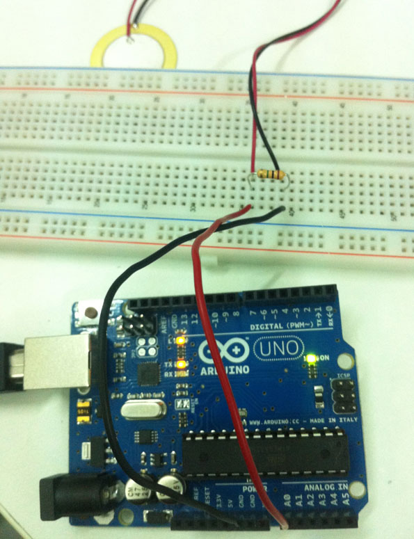
STEP 1_CONNECT THE ARDUINO BOARD
CODE_Reading and Sending Piezo Value. I have use the bread board to
test the piezo value and be able to stablish a range of values from which the sensor will react.
// Reading and Sending Piezo value
// In order to connect the piezo to the analog input we need to add a big resistor
// to limit the current that can be produced with a big knock.
//             1M
//   GND --+-/\/\/\/-+-- Analog 0
//         |         |
//         +--PIEZO--+
//

void setup()
{
  Serial.begin(9600); // Configuration of the serial Port at 9600 bauds
}


void loop()
{
  int piezoValue;

  piezoValue = analogRead(0); // Reading the analog value from analog Port 0
  Serial.println(piezoValue); // Sending the value through the Serial Port and End line
  delay (100); // Small delay to be able to read and not saturate the Port


}
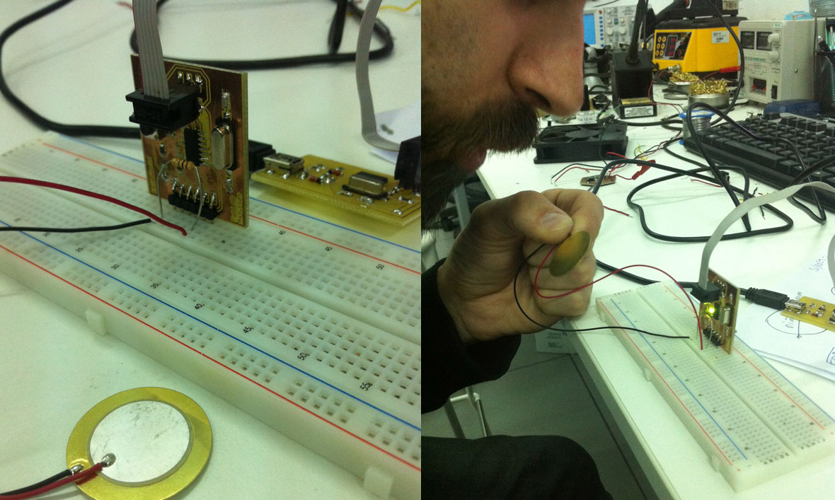
STEP 2_NOW WE CONNECT THE HELLO WORLD BOARD
CODE_The code now is reading the analog value and doing sth only if the value is >20.
// Reading and Reacting to Piezo value
// In order to connect the piezo to the analog input we need to add a big resistor
// to limit the current that can be produced with a big knock.
//             1M
//   GND --+-/\/\/\/-+-- Analog 0
//         |         |
//         +--PIEZO--+
//

void setup()
{
  pinMode (8,OUTPUT);
}


void loop()
{
  int piezoValue;

  piezoValue = analogRead(1); // Reading the analog value from analog Port 1 (RX on the ftdi connector)

  if (piezoValue>20)
  {
    digitalWrite(8,HIGH);
    delay (200);
    digitalWrite(8,LOW);
  }


}
I have measure with 2 diferent tyes of sensors:
1_A voltage SENSOR_PIEZO
2_A resistive SENSOR_LDR