
I was really excited to start the "Make Something Big" project using the CNC milling machine. I imagined myself mastering the tool, making a stunning line of modern flat pack furniture and becoming fabulously wealthy. Needless, to say that did not happen.
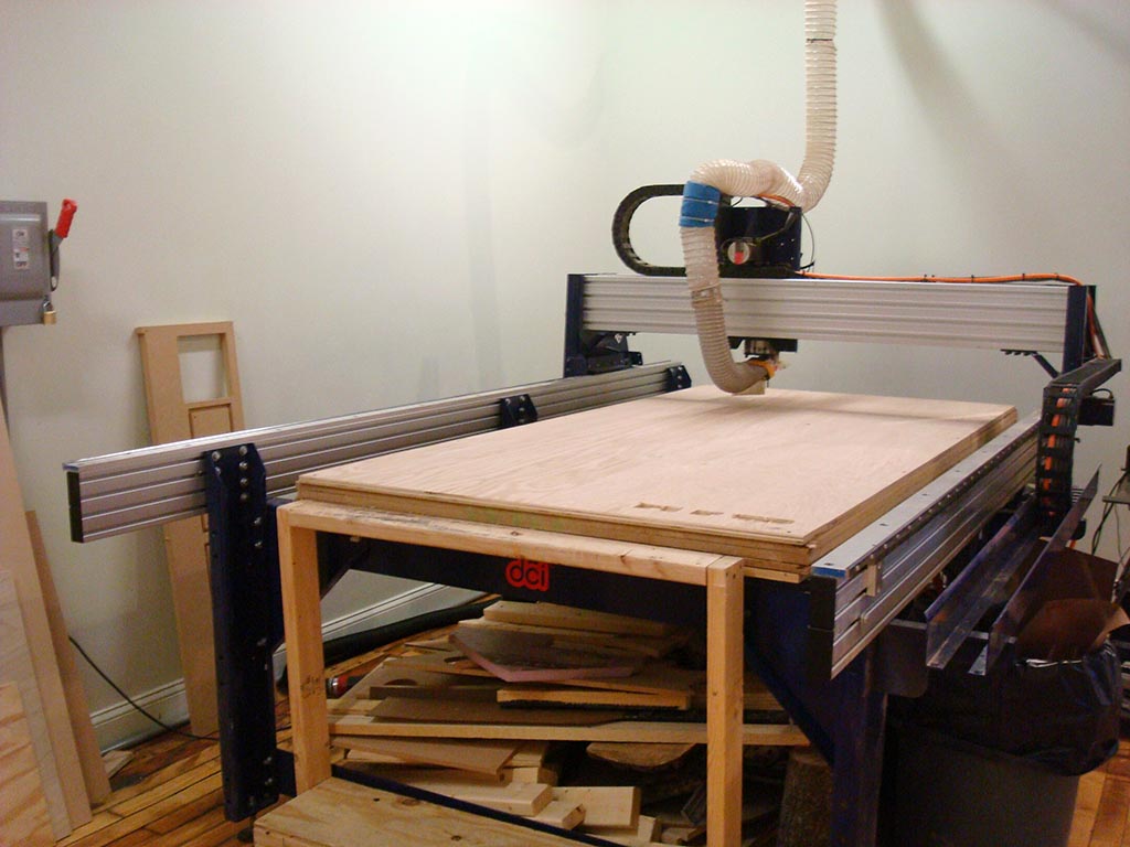
ShopBot!
Because this was a big project and we have a fairly large group in Providence, I wanted to make something that was going to have a minimal amount of joints with pieces that could be repeatedly cut out. I own a replica of the well known George Nelson Platform Bench and thought this would be a great piece to replicate one more time – so I made a replica of a replica. I took measurements of my own bench to get an idea of joint and piece sizes knowing that I would have to tweak those based on the thickness of my plywood piece.
I drew up my design in AutoCAD since that is a program I use on a daily basis for work. It was quick and easy to get the initial layout drawn up. Initially I drew in all of the chamfers within my CAD file, exported it as a .dxf file and transferred that to the computer connected to the ShopBot. I placed my vectors using the VCarve program but didn’t make any other edits. I selected a couple of pieces to be my test cuts from a piece of ply that was already screwed in place on the ShopBot bed. The test cuts came out but the machine seemed to be making some erratic cuts (later discovered to be un-joined polylines in AutoCAD) and the chamfers came out completely wrong. Through the magic of Google, I learned that many people have had issues with chamfers in .dxf files and that it’s best not to use them.
Poor quality test cuts
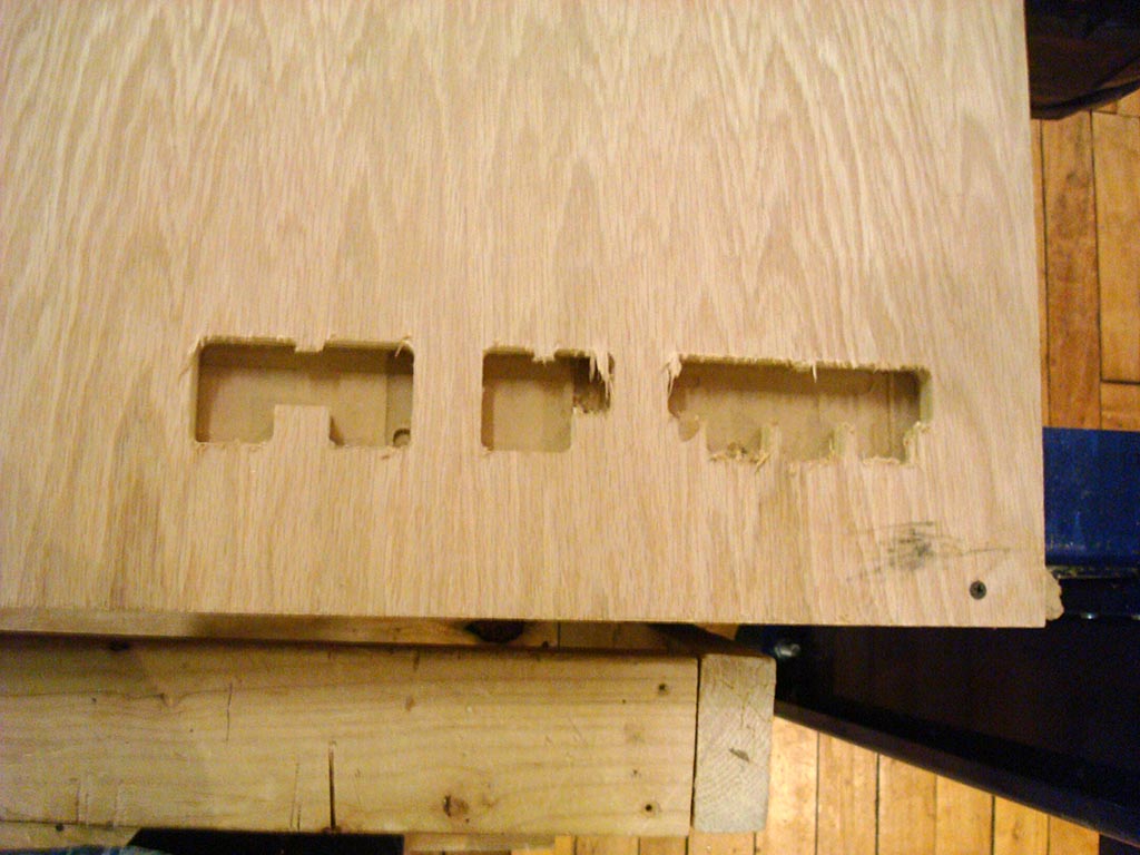
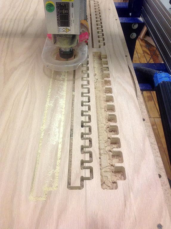
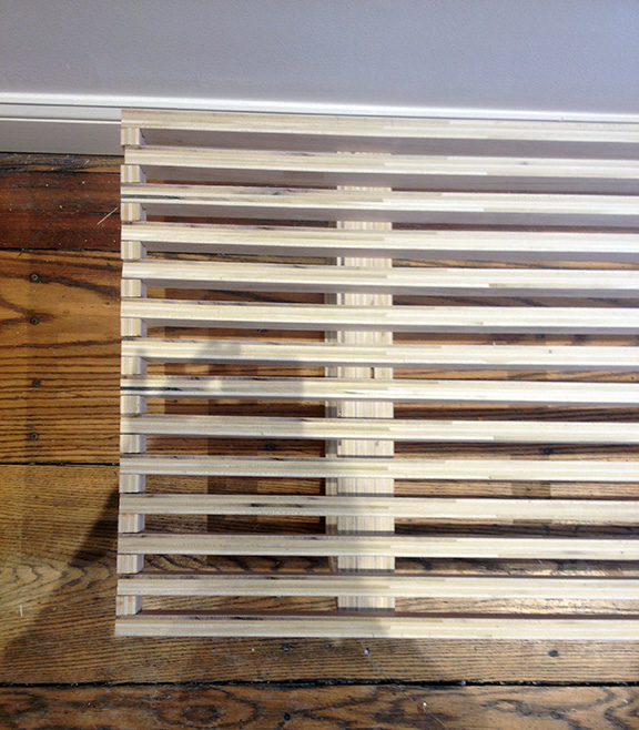
I spoke to a couple people in my group about the issues and learned that adding the chamfers in VCarve is extremely easy; just draw everything as right angles in CAD and then add the chamfers and fillets in VCarve. I followed that process for the second round of test cuts and that resulted in much better chamfers although the joints were still not a great fit.
IMAGE
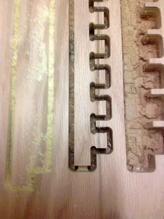
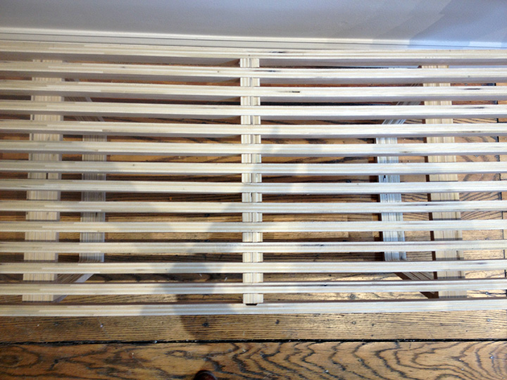
For the third test cut, I tweaked the drawings a bit more based on the dimensions I got from the calipers. It was important to measure the board that I was cutting from because I found variations between different sheets of plywood. The third test cut resulted in a joint that was a press fit (with the help of a rubber mallet) and I felt like I was ready to cut all of my pieces.
IMAGE
I used the calipers to measure the plywood sheet that I was going to cut all my pieces from and found variations in thickness at each of the edges of the board. I took an average of the measurements and hoped it would come out ok. Taking a visual survey, I thought the board looked pretty flat with minimal warping but once I put it on the ShopBot bed, the warping was pretty obvious. I secured it with screws in the corners and along the sides and thought that was going to be enough. Efficient use of material was an important goal for me on this assignment. I wanted to have as little material waste as possible; I closely spaced all my pieces together on the layout giving an offset of an inch between each piece. When calculating this offset, I didn’t consider the thickness of the mill (1/4”) and how that dimension would reduce the offset a ½” overall because I wanted to make outside cuts.
Using VCarve Pro I brought in my final CAD layout, this time bringing it in as a .dwg file. In AutoCAD I had drawn all of my lines as right angles to each other and added the chamfers in VCarve; I also made sure to join all the lines together so the machine would read the outline of my shape as one vector instead of multiple vectors. I went through the process of setting my origin, zeroing out the z-axis, creating my g-code and I was ready to go!
Everything started off seemingly okay. I was watching the mill closely to make sure that the cuts were accurate and they seemed to be matching the file. I had set the mill to make three passes at ¼” inch with tabs to hold the pieces in place. On the third pass and final pass, the piece jumped out of position and I immediately hit the “Stop” button. After several minutes of looking at what happened with some experienced members (thanks Larry and Kenzo!) we were able to figure out that the cutting depth I had set was too deep so the tabs hadn’t been cut out and the piece was not secure. Once the final pass came around, the piece was loose and jumped around from the force of the mill. I reset the cutting depth, made the tabs a bit thicker and started again.
I cut through the tabs!
Without any tabs to hold the piece steady, the force of the mill moved it around resulting in some pretty wonky cuts.
Once again, everything started off seemingly okay. The mill was cutting the correct shape and this time I could see the tabs. I paused the cut to make sure the tabs were in place and they seemed thick enough to keep the piece secure. I restarted the mill and continued along.
Try, try again.
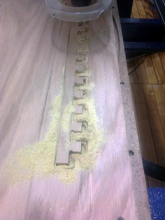
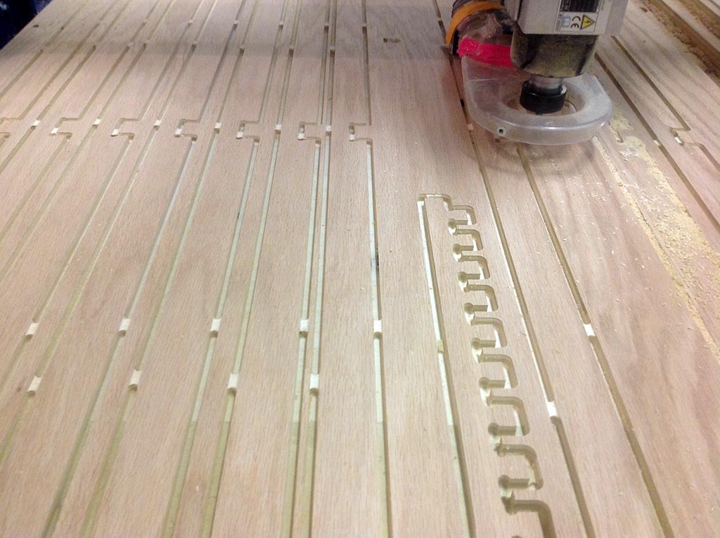
Trouble started on the third cut. Everything was seemingly okay until the final pass of the mill on the third cut – and then the piece jumped around in its spot. I stopped the machine and Larry, Kenzo and I brainstormed on what was happening. This is where the offset between the shapes created problems.
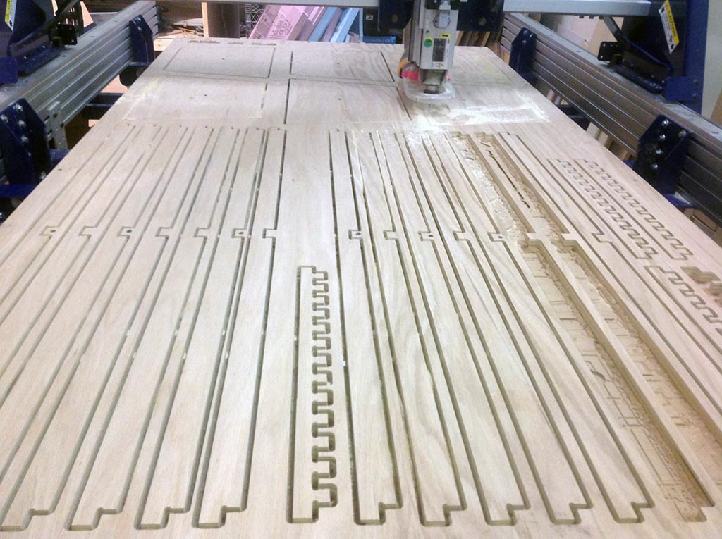
Tabs
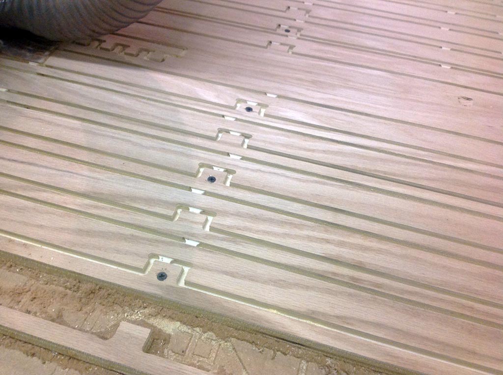
We were able to figure out that the small distance between each piece created an inherit instability in the plywood. Because I didn’t calculate for the thickness of the kerf when I laid out each piece and the kerf was roughly 1/4” wide, the distance between each piece was not 1/2” wide, but only 1/4”. I added more tabs and also screws to help stabilize the pieces. This strategy finally held everything together and I was able to complete the cuts without any more problems.
More tabs
Tabs and Screws
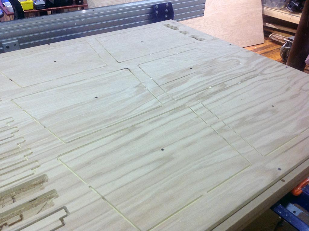
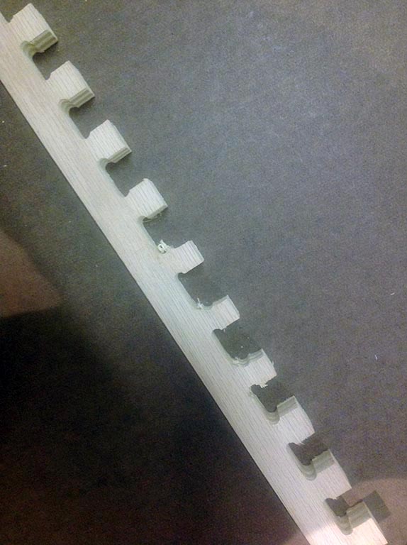
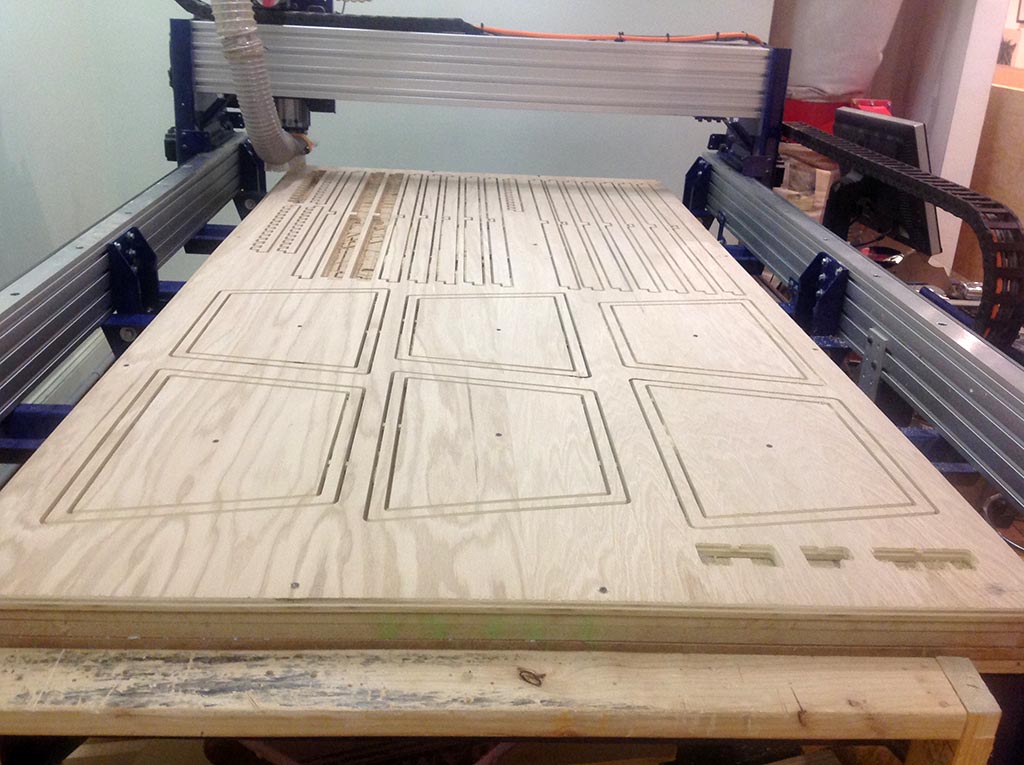
Finally, the ShopBot can finish its run!
Although the tabs and screws held everything in place, it took some serious elbow grease to saw through all of those tabs.
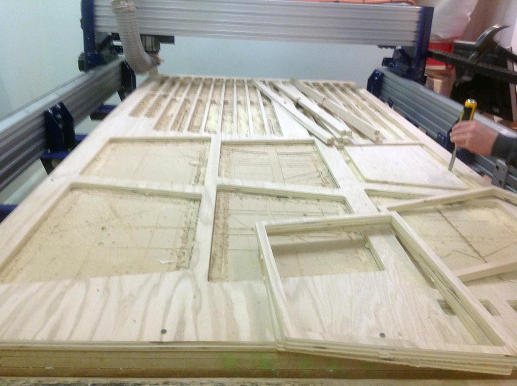
With all of my pieces cut, I was very eager to put them together and see what I had made. Needless to say, I was a bit disappointed. I reassured myself by acknowledging that the pieces needed to be sanded and finished before it would come together nicely. For some reason, I imagined that finish work was not necessary with a ShopBot. I learned that it absolutely is necessary.
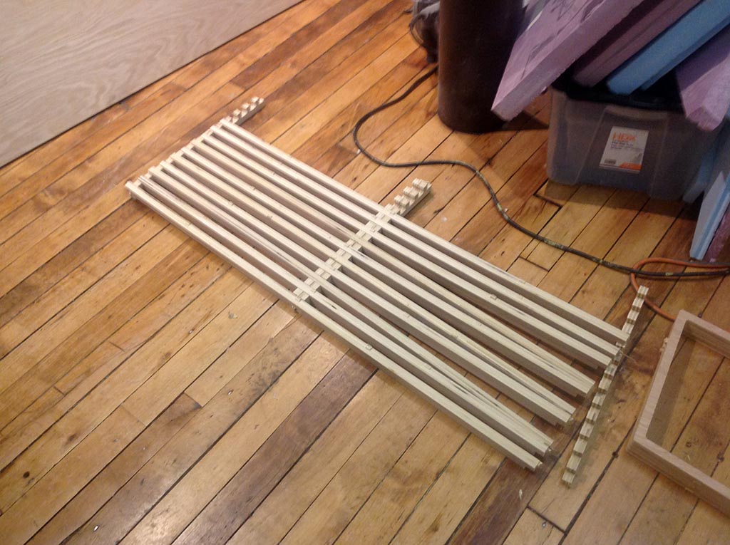
Once all of the pieces had been sanded, I felt a bit relieved.The pieces fit well into their joints but not all of them turned out to be press press fit. Because its a bench and I wanted it to be fairly sturdy, I chose to apply wood glue to the joints before I put each piece in for final placement. I also screwed the top to the legs.
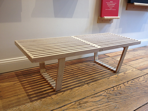
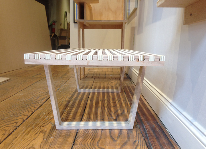
Although there are a couple places where the details didn't come out as nice as I had imagined, it came together better than I thought it would when I initially looked at all of the cut pieces. Overall I am really happy with the final outcome.
Final Product
Jessica Metz Fab Academy 2015