
For my project this week I wanted to use a sensor that would capture sound and somehow get the sound to become a visual output. I found a project that uses an electret microphone to capture sound, uses Arduino to read the sound and then sends the data to Processing to make text dance to the rhythmn of music. I'm not looking to make text dance but I like the idea of taking an invisible thing and making it visible.You can see that that project example here.
I am very new to circuit building so I spent a lot of time looking at examples on the internet and also on the Fab Academy webpage. I decided to combine the hello.mic.45.cad board and the hello.echo board I made a couple weeks ago for Week 6 Electronics Design.
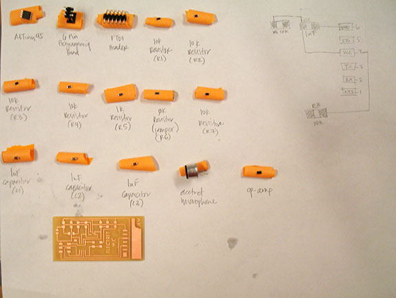
I haven't quite figured out the best workflow when starting a circuit design but it was easiest for me to begin by printing both boards I wanted to reference and begin drawing a circuit diagram to better understand how the components worked together. Although this is a tedious process, by the time I finished I felt pretty confident that I understand how the board was meant to function. I made a list of all the component parts that I would need and started my schematic in Eagle. I used my hello.echo board as a starting point so I didn't have to spend the time loading all new components from the library. The final component list came to the following:
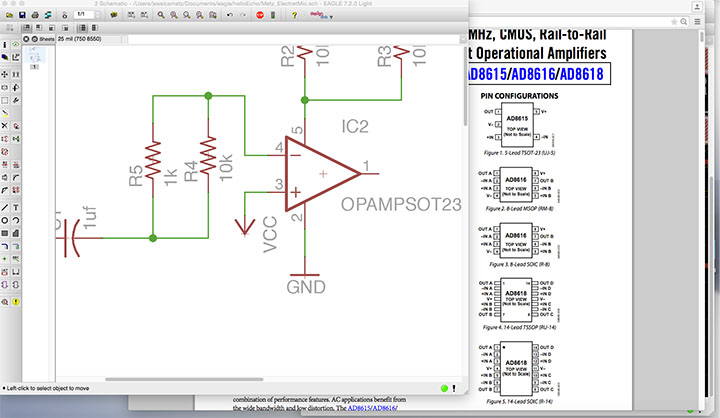
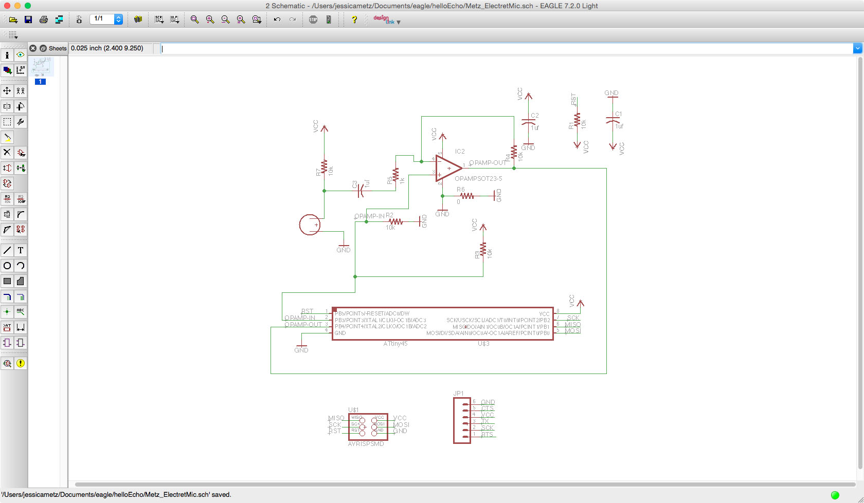
The Eagle schematic took me most of the day to figure out; I wasn't confident that I was interpreting the layout correctly because this was significantly more complex that the previous boards I had worked on. When I was finished placing all my components in the schematic view, I switched to the board view to trace the yellow connections. At this point I started switching between the two views quite frequently because I would find an error in the board view and correct it in the schematic. I spent extra time figuing out the op-amp and had to refer to the specification often to figure out the pins.
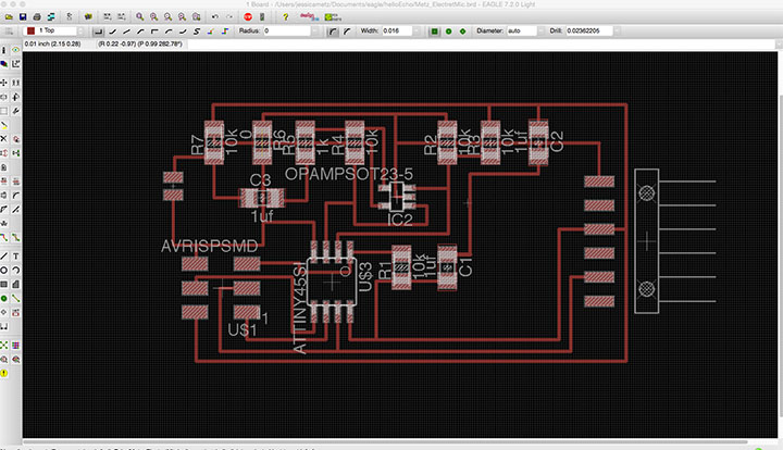
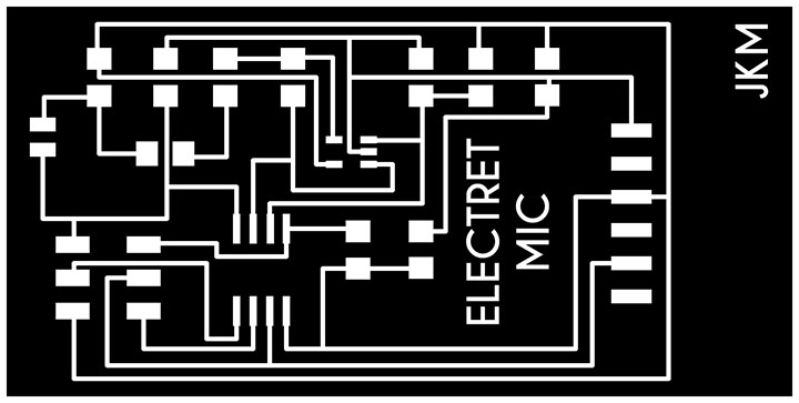
Once I was confident that the components were correctly connected together I started routing the traces. I incorporated a jumper into this design to try something new since it is also a trick listed under the Eagle tutorials page. I'm trying to incorporate as many different lessons as I can to learn as much as possible. Once the routing was complete, I checked the relationships again and then created my .png files for the board and the interior following the Eagle tutorial instructions we used for Week 6.
PNG file for Electret Mic
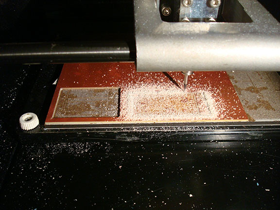
Let the milling begin!
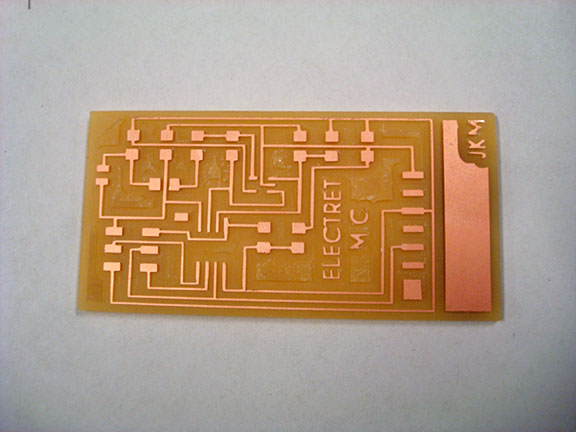
The milled board
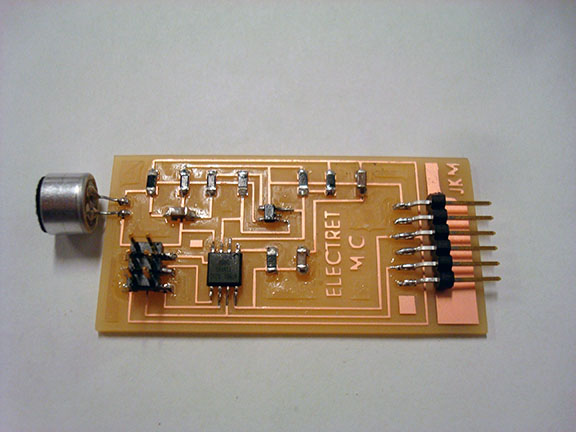
Finished board with components
The final step was to write a program that would allow the board to pick up sounds and record that information. Ideally, I could program the board to pick up sounds and trigger an LED device.I worked with some existing Arduino examples that I found online; Shawn helped me adapt Neil's code for Arduino.
I was very excited to run the program and see the board picking up real sounds. This mic seems to pick up a lot of background noise and was picking up values a bit inconsistently; deeper sounds were picked with the most consistency. I'm not sure yet what to change to modify the board so it's more accurate or responsive to different sounds but this will be something I am working on for my final project.
Jessica Metz Fab Academy 2015