
The assignment this week was to design and make a wireless internet printed circuit board using the ESP8266 wifi chip. I really struggled with making a board and had to make several iterations because I kept getting the through holes wrong.
ESP8266 Wifi Chip
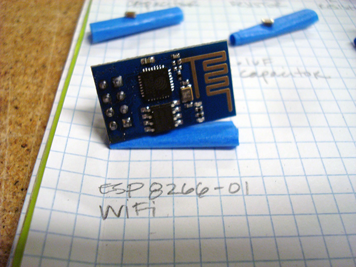
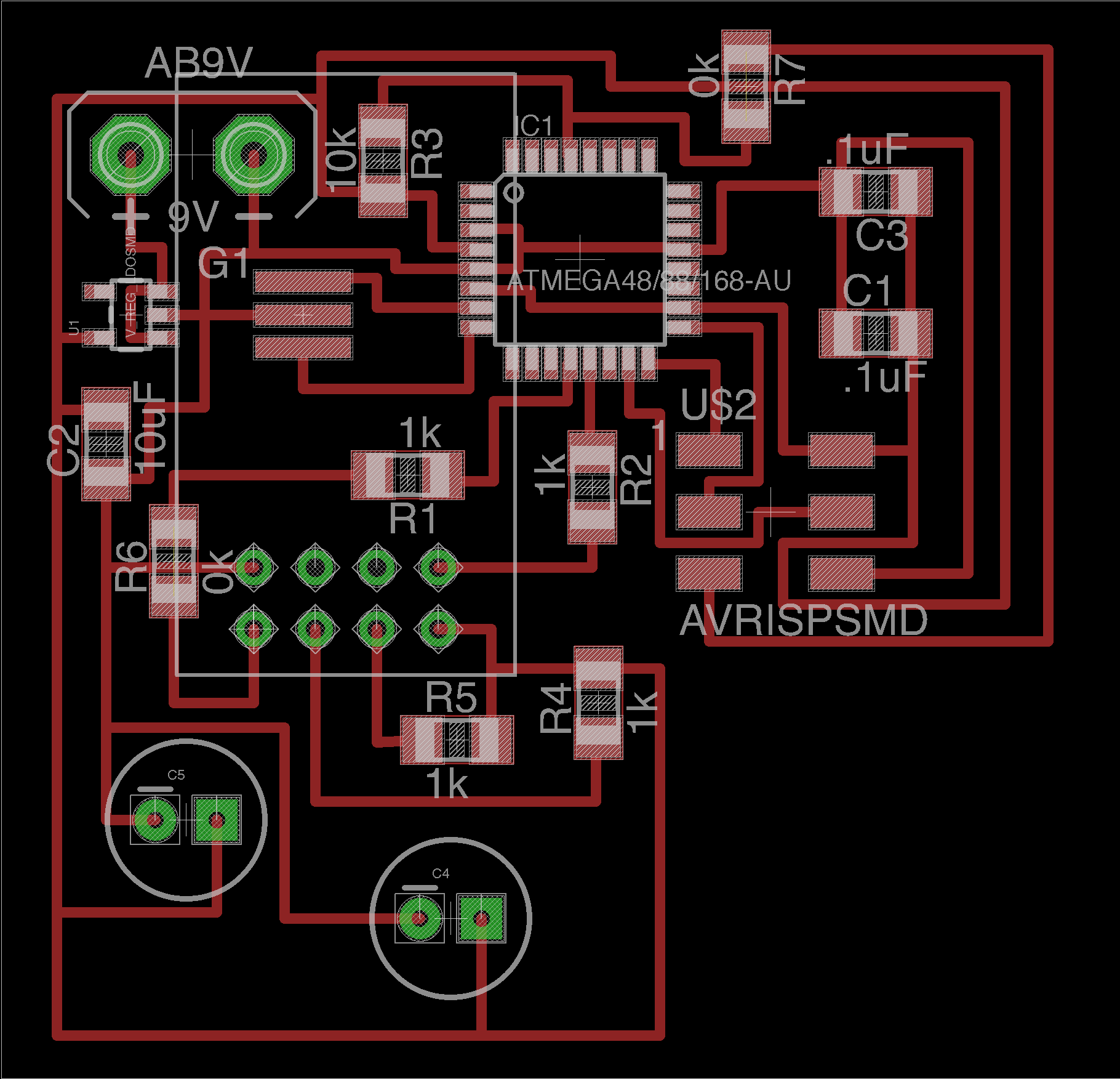
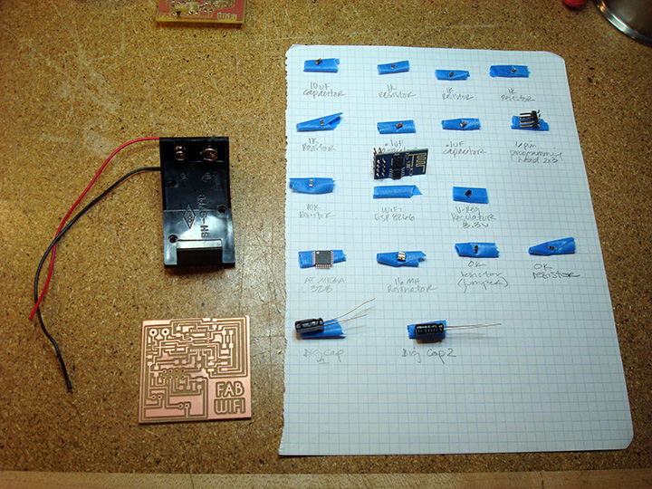
I started my design by figuring out which components were actually needed on the board.
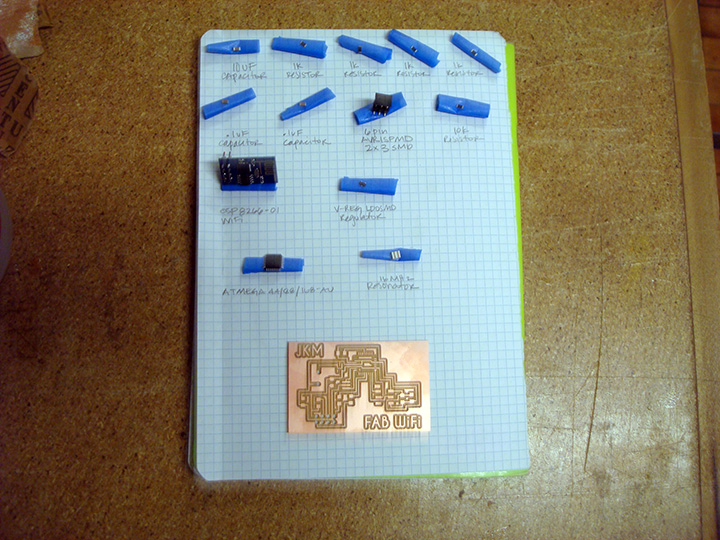
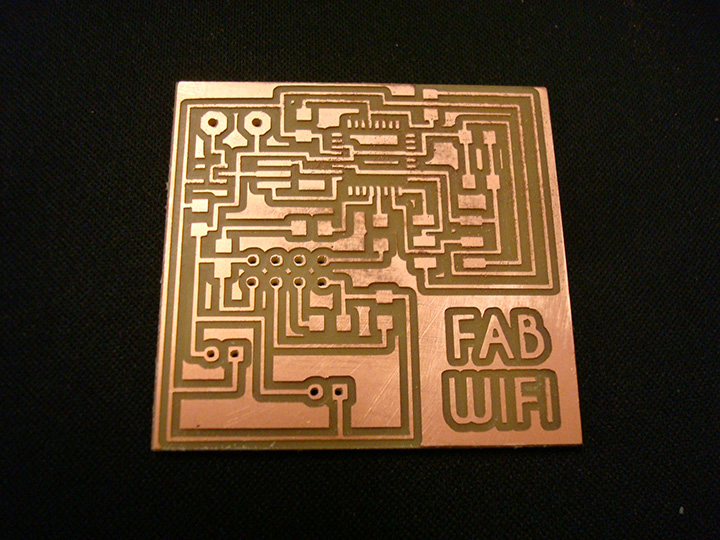
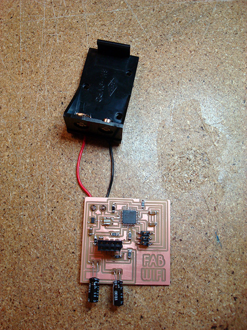
I had several components that needed to have through-holes drilled in my board: the wires that connected to the battery, and later on, the two capacitors and 8-pin adaptor that would hold my wifi board. Initially, when learning how to mill our PCB's we had been making black and white PNG's; the mill would then cut out around the white parts. In doing through-holes though, I found that this method ended up making holes that were much larger than drawn. I had to make a separate black and white PNG file just for my through-hole cuts and inverted it so the mill would cut the inside of the hole circle instead of the outside.
These holes are much too large for soldering.
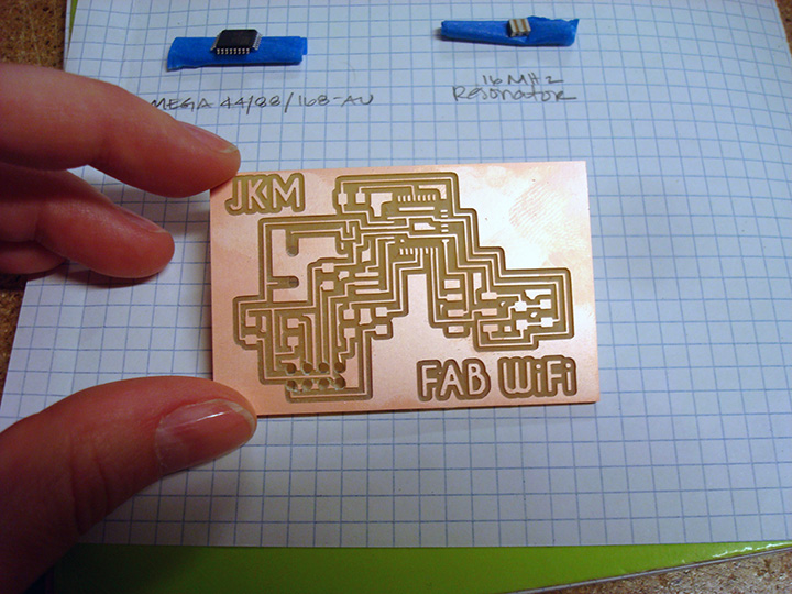
I knew the holes were too big for solder but I was being stubborn and thought if I could just get enough solder on the board then I could make it work. What I didn't realize was that in trying to get the extra solder on the board, it would set quickly and when I tried to move it around, the solder ripped off my traces. So lesson learned. Do things right the first time. Time to mill another board.
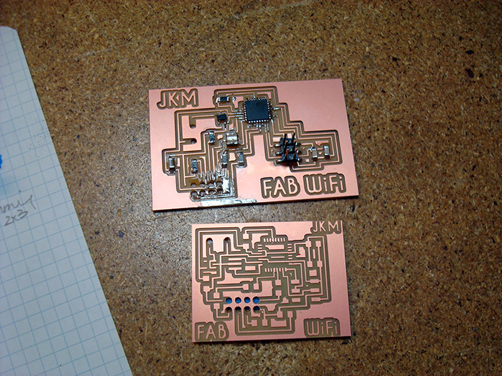
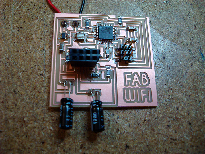
At this point in the week, I was really grateful to have such an open working group because it was through everyone's trial and error process that we were able to figure out as a class that we needed some hefty capacitors to get the board working its best. I needed to make a new board anyway after destroying my previous one, so before milling I modified my Eagle file to incorporate the new capacitors.

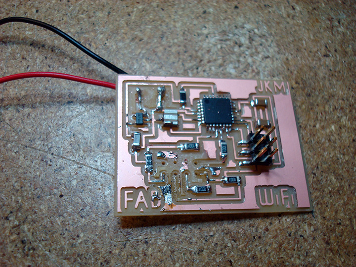
You can see the nice solder pads around the through holes in the newly milled wifi board. These pads helped immensely when trying to solder in tight spaces.
Shawn sent us a code to test out our wifi boards but programming the board was a bit tricky. I wrote out step by step instructions for myself because I knew I would need to refer back to this process for my final project.
Steps to get the wifi board working:
Step 1: Make sure the battery is fully charged to power the board!
Step 2: Plug in the programmer to the USB drive and connect to the wifi board's 6-pin programming header. You do not plug in the ESP8266 component at this time.
Step 3: Choose the appropriate Arduino settings. Instead of using the "Upload" button, choose "Upload Using Programmer". This was specific to the programmer we were using in our group - the same may not apply to everyone.
Step 4: If you are able to successfully upload, disconnect the programmer from you USB and remove it from the board's programming header.
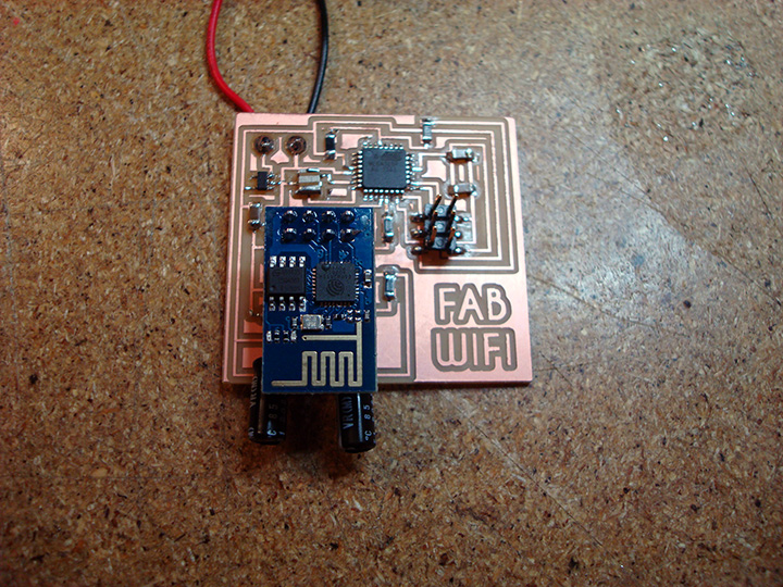
Step 5: With the battery connected, plug in the ESP8266 to the board's 6-pin programming header. If the chip is successfully powered, then a red LED will turn on. If the wifi is working, you will see a flashing blue LED.
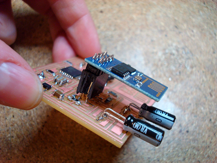
Step 6: Connect the wifi board to the FTDI breakout board. For my design I had to connect the RX and TX on the wifi board to RX and TX on the FTDOI breakout board. Plug the FTDI into your computer's USB drive and click on the Arduino Serial Monitor. If everything works correctly, you will see the current weather data in New Zealand.
Jessica Metz Fab Academy 2015