
My final project has come down to this: a single working prototype of my light fixture that will turn on and off depending on real-time wifi data read from the internet. To plug my light into the wall I will also be making a diy version of a PowerSwitch Tail.
Wifi Board
A big part of my final project was incorporating my wifi board that I completed a couple weeks eaerlier. I struggled for multiple weeks to get my board working but it was an integral part of my final project so it paid off to hack my way through it. Detailed documentation for my wifi board can be found here.
Solid-State Relay
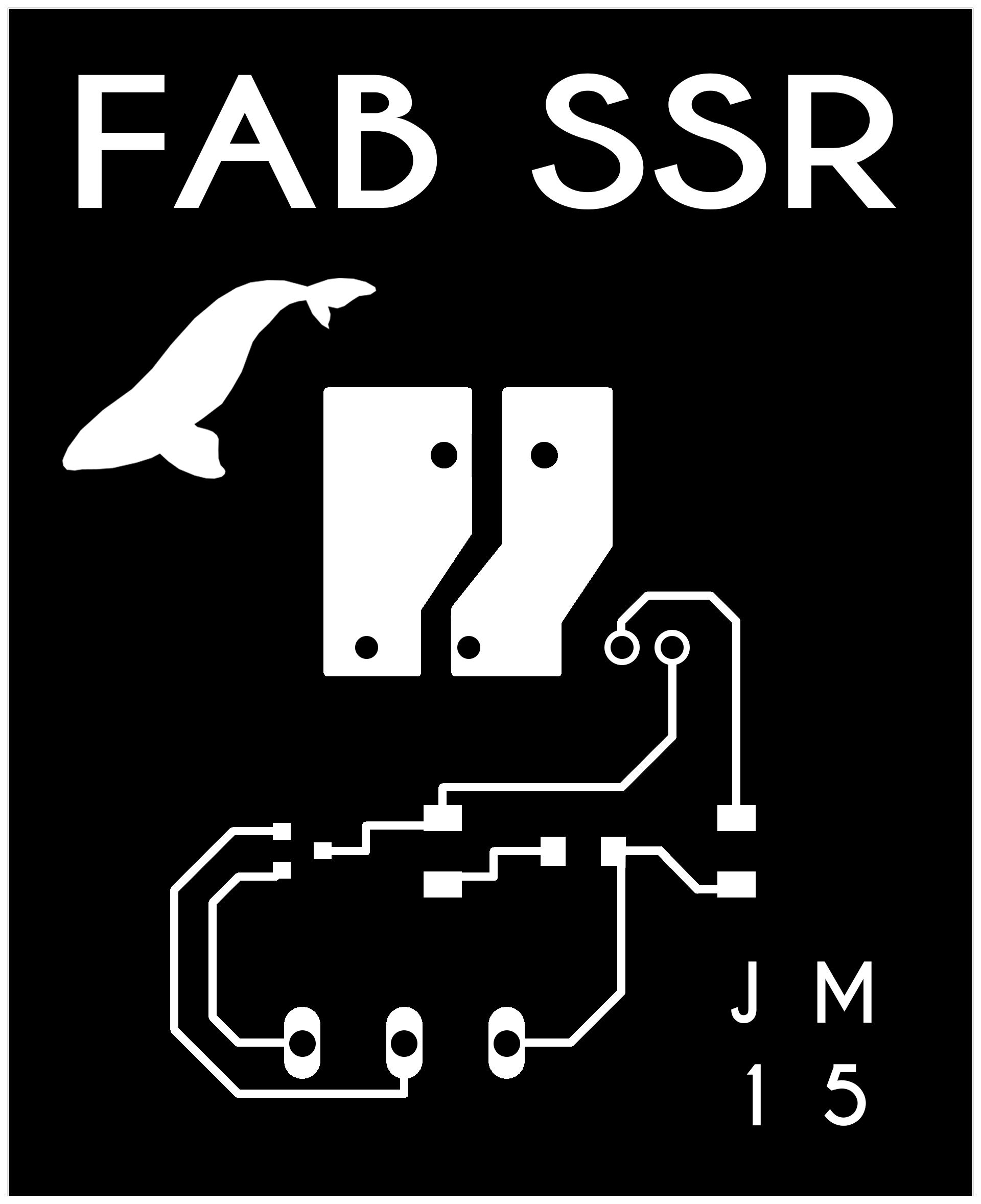
The second main component of my final project was making what is commercially known as a "PowerSwitch Tail II". This device allows you to safely control an outlet device without exposing any 120VAC voltages. You can plug in any standard 120VAC 3-prong outlet to be controlled by most any microcontroller. To make your own version, you need to make a solid-state relay board, also known as an SSR board. I used the Eagle design files available here, on Sparkfun as a reference. Shawn, our lab guru, helped me figure out what components needed to be changed to incorporate components that were in available in our Fab Inventory. My design incoporates an n-mosfet instead of the transistor used in the Sparkfun Solid-State Relay Kit. I drew up the design in Eagle and milled my board using our Roland milling machine. I can mill a board pretty quickly by now!
SSR Schematic

SSR Traces
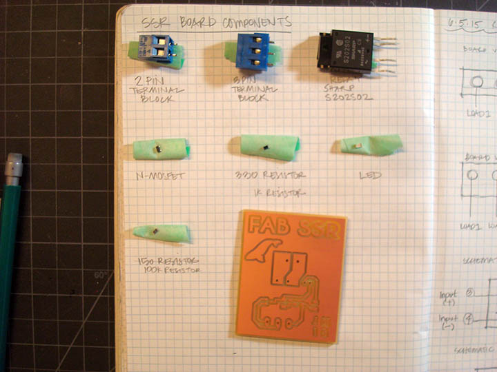
SSR Components
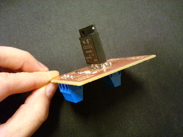
Putting the board together - there's not much to it because the magic doesn't happen until you start attaching the other elements to the board.
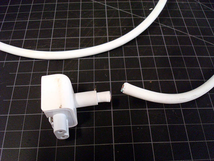
The SSR board needs to be connected to a GFCI outlet that you will use to plug in your AC device and also connected to a power cord that you will plug into a standard wall outlet. I wanted the SSR board to be housed in a clear, acrylic case since the interesting part of the PowerSwitch Tail is really what's happening on the inside, and I wanted to see the parts. Aesthetically, I wanted to use white power cords for the power sources for the PowerSwitch Tail and for my light fixture; somehow black seemed too harsh. I had an old Mac computer power cord lying around the house and also a white extension cord. I figured those would work perfectly and wouldn't cost me any extra money since I wouldn't have to buy new ones.
In order to connect the power cords to my SSR board I had to take them apart. I cut the wierd cube end off the mac cord leaving the three prong end attached. I then used an knife to remove the outer white casing in order to expose the three wires on the inside; these wires should be green, white and black. I made sure to cut off about 6-inches of the casing to give myself adequate length to work with; I then removed approximately 1-inch of the green, white and black casing from the ends of the wires to fully expose them. I cut the black wire shorter than the others because I needed that piece to connect to the relay. I made hooks out of the tinned wire ends to help with the connection to the screws on the GFCI.
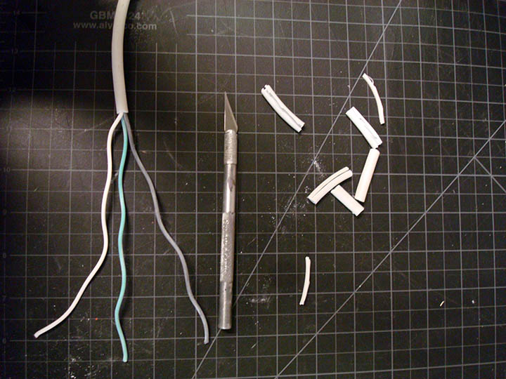
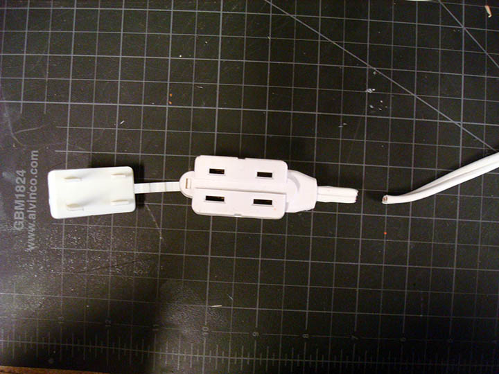
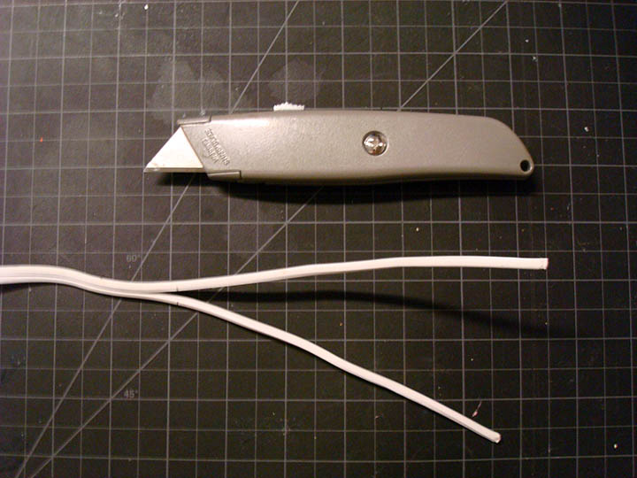
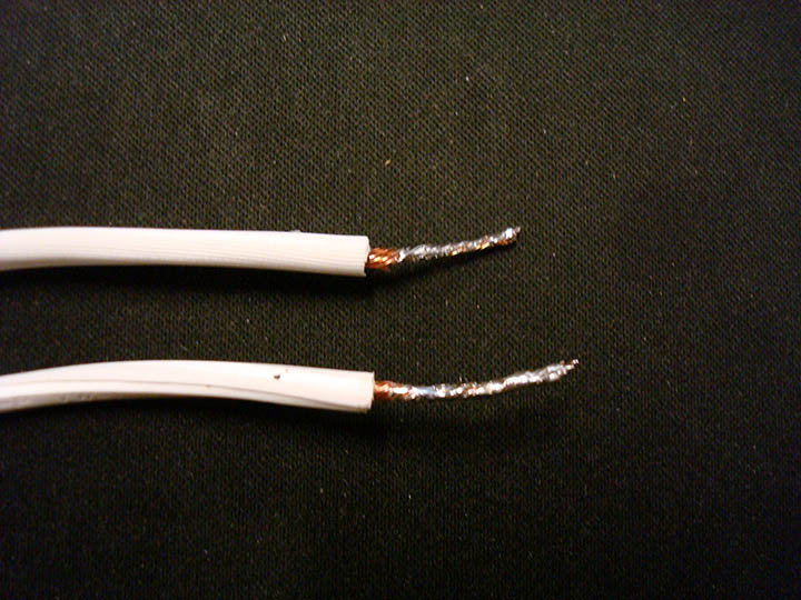
With the extension cord, I cut off the receiving end and left the two-prong outlet attached. The two wires that made up this cord were fused together so I used my utility knife to split them down the middle being careful not to cut into the outer casing. I cut back the white portion of the wires in a similar way to the other cord leaving about an each of fully exposed wire. This is important to do because it allows you to tin the wire ends making the connecting to the SSR board, and the GFCI, much easier.
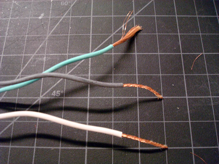
Tinning the end of the wires
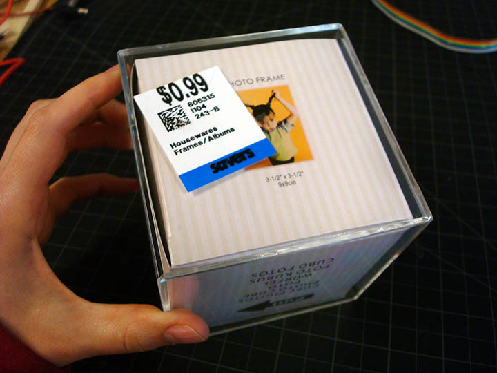
At this point, I needed to construct the enclosure. I bought a used acrylic photo cube that slid apart in two pieces from Savers, a local consignment store, for 99 cents and a GFCI outlet from Home Depot. I wanted to laser cut holes in the photo box for the outlet, the power cord, the microcontroller wires and for the GFCI screw holes. I drew everything up in Autocad and Illustrator, covered my acrylic with some transfer tape to prevent burns and cut. It took a couple iterations before I got the settings right but luckily I bought several photo cubes to test on before cutting the final.
Acrylic photo box from Savers
With my enclosure complete, I moved on to connecting the power to the SSR board and the GFCI. Luckily, the GFCI outlet came with very detailed installation instructions. I took my time reading them, made sure I was connecting to LINE and not to LOAD, and triple checked my work before moving to the next step.
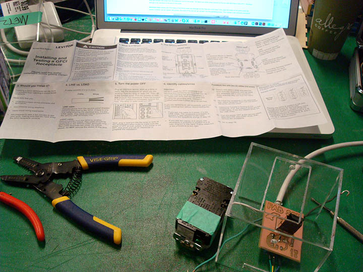
GFCI Instructions

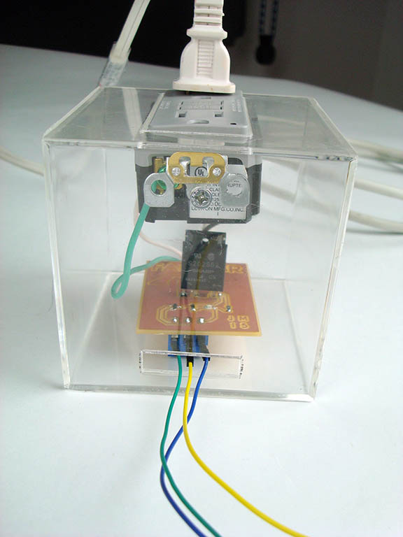
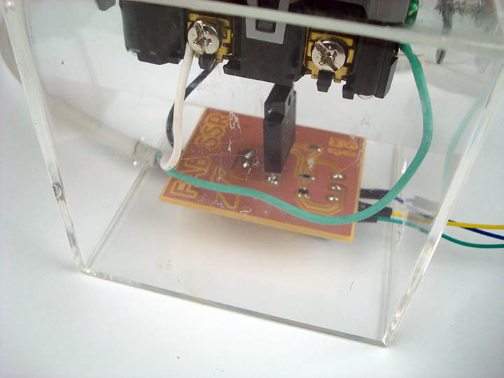
In order to properly connect the grounded power cord to the GFCI, I had to cut part of my black wire off - the portion of the black wire that is still connected to the power cord gets inserted into one side of the two pin terminal block. The newly cut, separated black wire gets inserted into the other side. When the power is off, this setup ensures that there is no connected between the two black wires. If anything goes wrong, the relay will kick off and the outlet will shut down. When 5V get sent to the coil, the relay flips from the 'off' state to the 'on' state connecting the two pieces of black wire; power is delivered to the outlet and the project is powered.
The black and white wires get connected to the outlet according to the written installation instructions and the green wire gets connected to ground. Microcontroller wires get connected to the 3-pin terminal on the other side of the SSR board. These wires will connect to my wifi board.
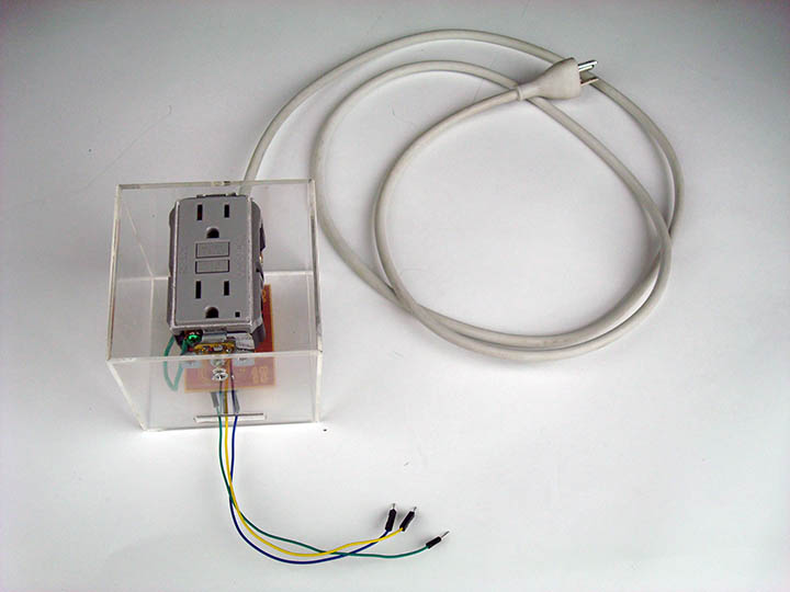
Complete SSR Board and Enclosure
Converting a Hard-Wired Light Fixture to a 2-Prong Outlet
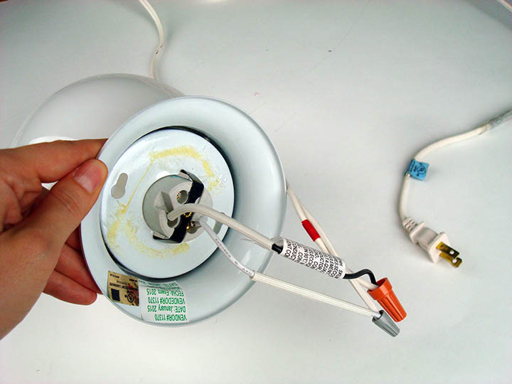
The light fixture I chose from Home Depot was actually a hard-wired ceiling fixture. This means that to install it in your home, you connect it directly to your electrical wiring instead of plugging it into an outlet. Since I had just made a PowerSwitch Tail, I wanted a light fixture I could plug in. Lucking its very easy to convert a hard-wired light to a 2-prong plug. Using a multimeter, I took my white extension cord I cut in the steps above and checked each wire to figure out which one was hot. Then I connected hot to hot and black to black using these little twisting caps that came with my light. I plugged it in to test it and voila! Pretty simple.
Programming the Board
The whole goal of my project was to use the real-time whale data to activate my light to turn on and off when a whale call was detected. One important element that I didn't think about though was the time of year - there are very few whales in Massachusetts Bay in June so there are very few whale calls. Instead of waiting weeks to test out a code that may or may not have worked in the off change I might pick up a whale call, I chose to use data I had access to and test to see if the system worked. I felt like if I could get all the parts and pieces to work together using different real-time data, then I could program it to detect whale calls when they returned from their migratory journey.
I ended up making small modifications to my original wifi test code. I programmed my wifi board like I had been doing for several weeks. It was pretty simple to connect the SSR board to my wifi board since I have a 6-pin programming header on my wifi board. Based on the Arduino map, SCK, MISO and MOSI correspond to Arduino pins 13, 12 and 11; pin 11 corresponds to MOSI so I chose to connect my control wire to MOSI on my programming header. Once it was programmed, I unplugged it from the computer and I connected the power, ground and control wires of the SSR board to power, ground and MOSI, respectively, on my wifi board. The wifi blue LED was blinking so I knew wifi was connected, and then...it turned on.
Miraculously, the code worked. And my light turned on for 2 seconds like I had programmed it to. When the wifi board connects to a weather data website in New Zealand, the light turns on for 2 seconds. It then turns off and searches for the connection again and repeats the cycle.
Take a look
Final Project Cost
Light from Home Depot = $8.47
GFCI Outlet from Home Depot = $15.98
Acrylic Photo Box from Savers x 3 = $0.99 x 3 = $2.97
All other materials from Fab Inventory or home = free
Staying up most of the night before final presentations with my fellow fabbers = PRICELESS
Jessica Metz Fab Academy 2015