
This week we have to redraw the hello.echo board and add an LED and a button.To do this, we will use a program called Eagle.
We are using the free version of Eagle since the functionality is good for what we are doing. My understand is that the free version will be fine unless you start making more complicated boards.Luckily, there is a very helpful tutorial here.After some time playing around, I found the program fairly easy to use since it seems similar to other CAD programs I have used in the past. The most complicated aspect of the program has been finding the correct component in the extensive libraries.
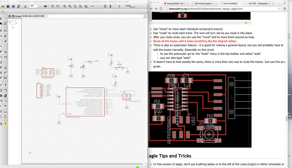
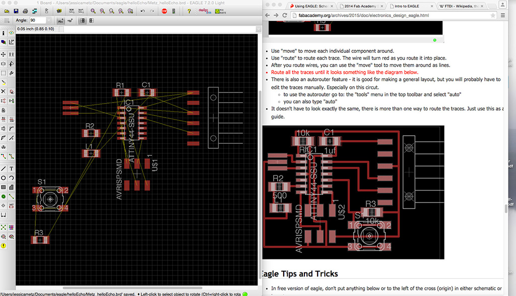
In Eagle, you start working in the schematic view and then once all the connections are made, you move over to the board view to draw your actual circuit connections.
Eagle Schematic View
Eagle Board View
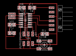
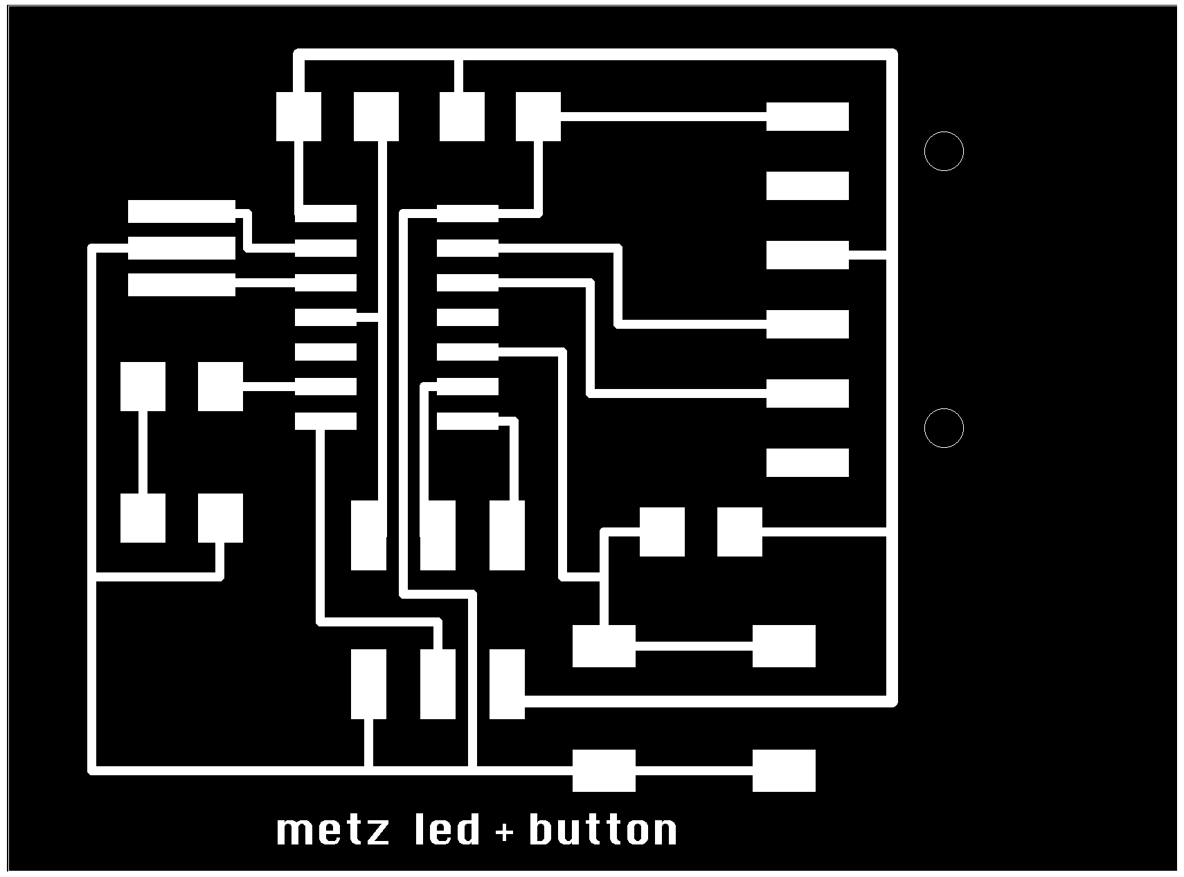
Final Layout
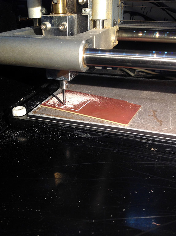
The first time I milled my board, the material was not well adhered to the base and ended up twisting off. Lesson learned. Now I know to really push down against the adhesive to ensure that a good connection exists between the circuit board material and the base material.
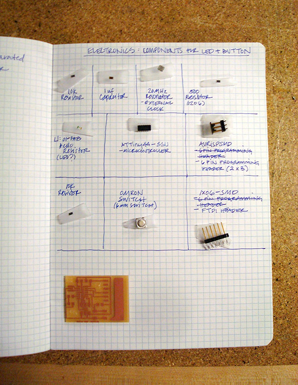
I cut out my second board and collected all my components for soldering. I'm sticking with my worstation setup that I designed in Week 4; I found it an efficient and easy way for me to place the components accurately.
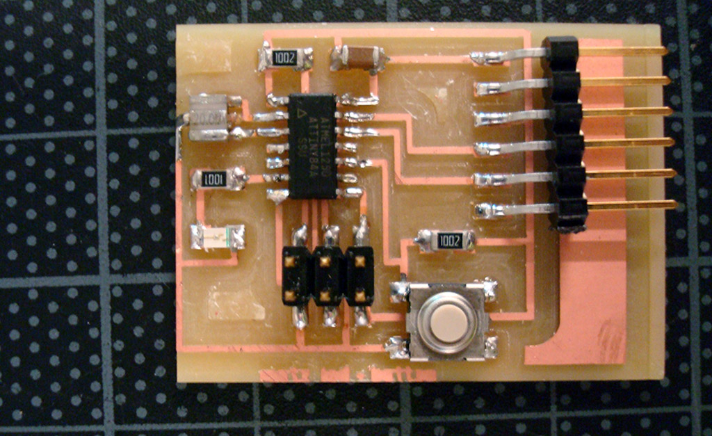
Finished board
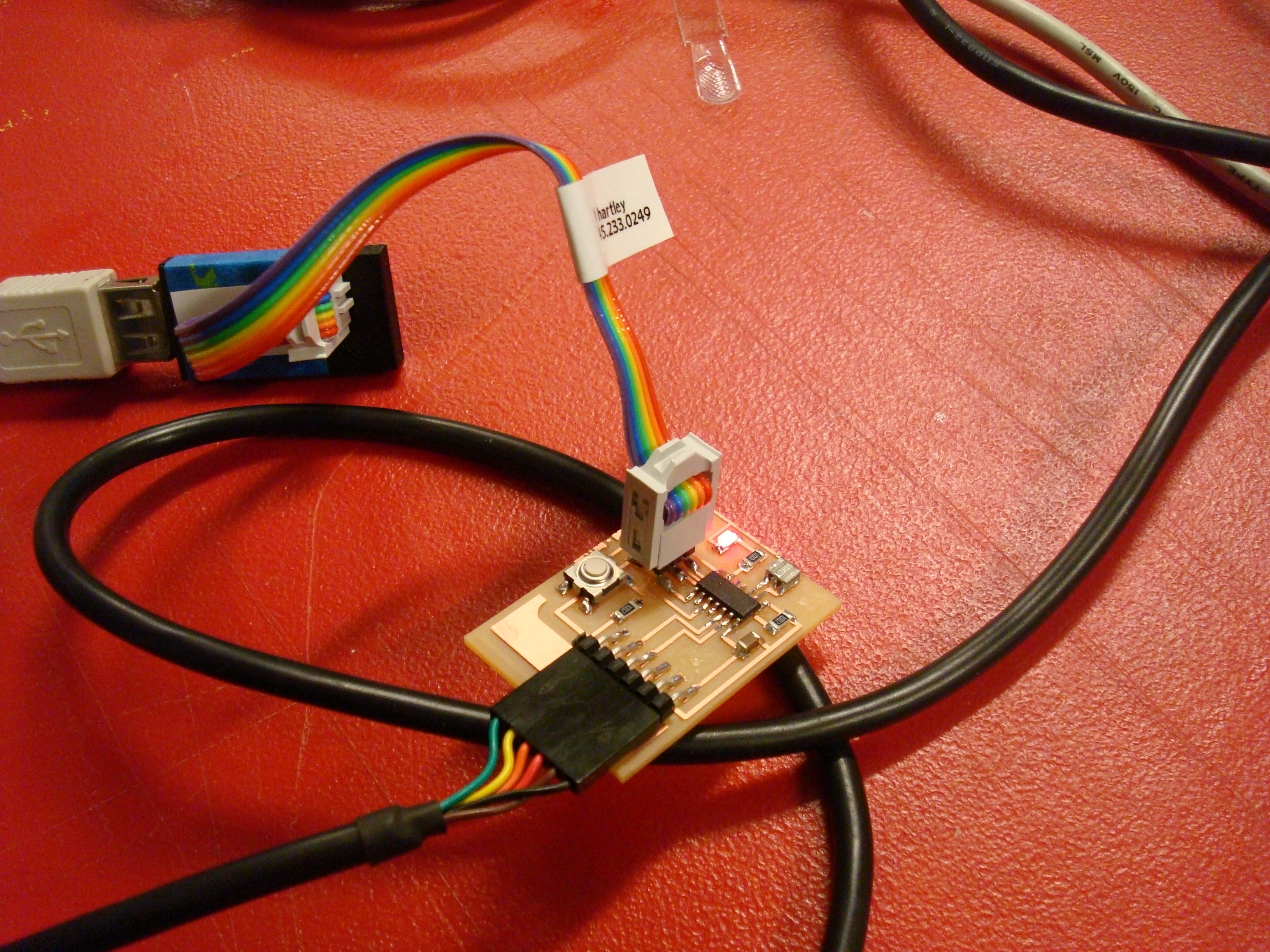
The LED works! I used my FabISP to program the LED board and then Arduino to blink the LED.
Jessica Metz Fab Academy 2015