Computer-Aided Design
Project Overview
For this assignment, I developed a digital model of a possible final project using computer-aided design tools. The project is part of a larger concept involving a functional device (e.g., autonomous vessel / electronic system), and this stage focuses on creating accurate 2D and 3D representations of its structure.
The goal was to design a model that can later be manufactured using digital fabrication methods such as 3D printing or CNC machining.
Software Selection
I used Autodesk Inventor for both 2D and 3D design.

I selected Inventor because it provides parametric modeling tools, precise dimension control, and allows a smooth workflow from sketch creation to solid modeling. Another advantage is the ability to export models in formats such as STEP and STL, which are commonly used for manufacturing and prototyping.
2D Design Process
The design process started with creating 2D sketches.
First, I created a new sketch and selected the appropriate reference plane. Using lines, arcs, and geometric constraints, I drew the basic outline of the boat hull. After creating the initial geometry, I applied dimensions to control the length, width, and other critical parameters.
The use of dimensional constraints allowed me to modify the design quickly while maintaining the overall shape of the model.
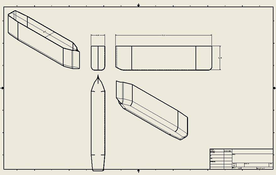
Screenshot: Initial 2D sketch of the hull.
3D Modeling Process
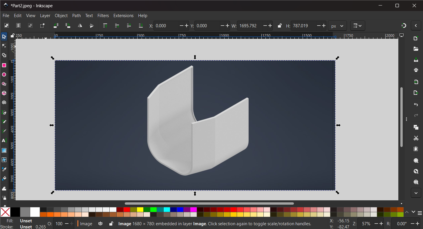
After completing the sketches, I converted them into a three-dimensional model.
The main hull geometry was created using the Extrude feature. Additional operations such as Fillet and Chamfer were used to improve the shape and remove sharp edges. Several design iterations were made to improve the overall geometry and prepare the model for manufacturing.
Because the complete hull exceeded the build volume of the available 3D printer, I divided the model into multiple sections. This approach allows each section to be printed separately and assembled later.
The final model consists of five individual parts that can be manufactured independently and assembled into a complete hull structure.
-
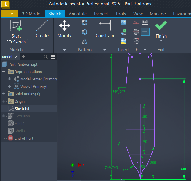
Create a Sketch - After I created the .ipt part, I started creating a 2D sketch.
-
Create 2D Lines - I used the tools in the Sketch tab, used all the necessary tools like Line, Circle, Arc, Rectangle, and Mirror for mirroring.
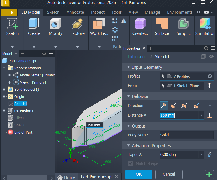
- Extrusion - Extruded the profile sketch by 150 mm, in the upward direction.
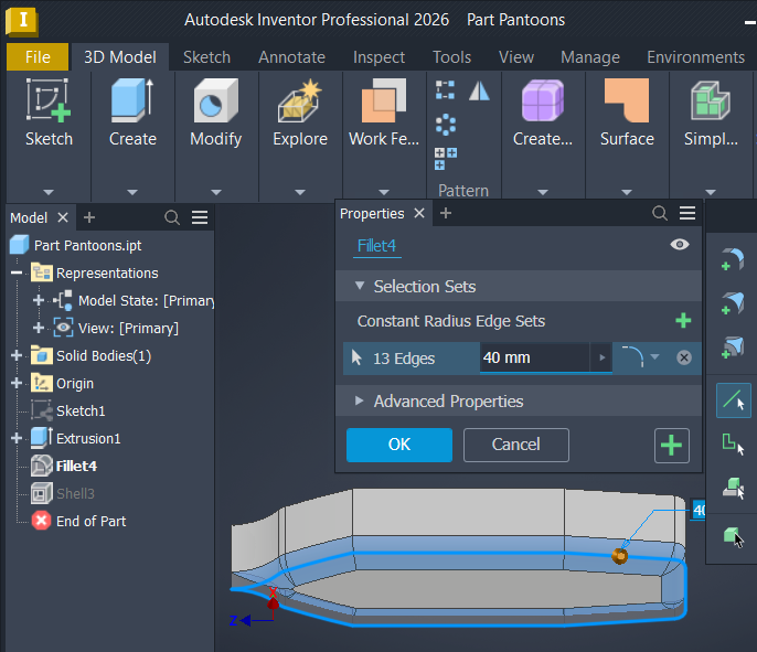
- Fillet (smooth edges) - I fillet the bottom of the model by 40 mm, all 13 ages that I have.
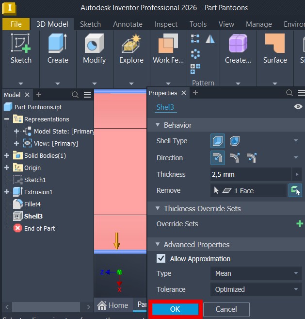
- Shell - For the shell the model at 2.5 mm thickness, choosing one face from the top.
Image Compression
The screenshots used in this documentation were originally exported at high resolution. To reduce website loading time and repository size, the images were compressed before uploading.
PNG image files were compressed using image optimization tools while preserving visual quality. This significantly reduced file size without affecting the readability of dimensions and design details. The screenshots used in this documentation were originally exported at high resolution. To reduce website loading time and repository size, the images were compressed before uploading.

I used GIMP to optimize and export the images. During the export process, I adjusted the image quality and resolution where necessary to reduce file size while maintaining clear visibility of sketches, dimensions, and modeling details.
The compression significantly reduced storage requirements and improved website performance without noticeably affecting image quality.
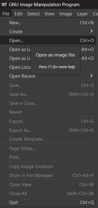
- Open - To open a image file, I clicked on the open button and selected the image file I needed to scale.
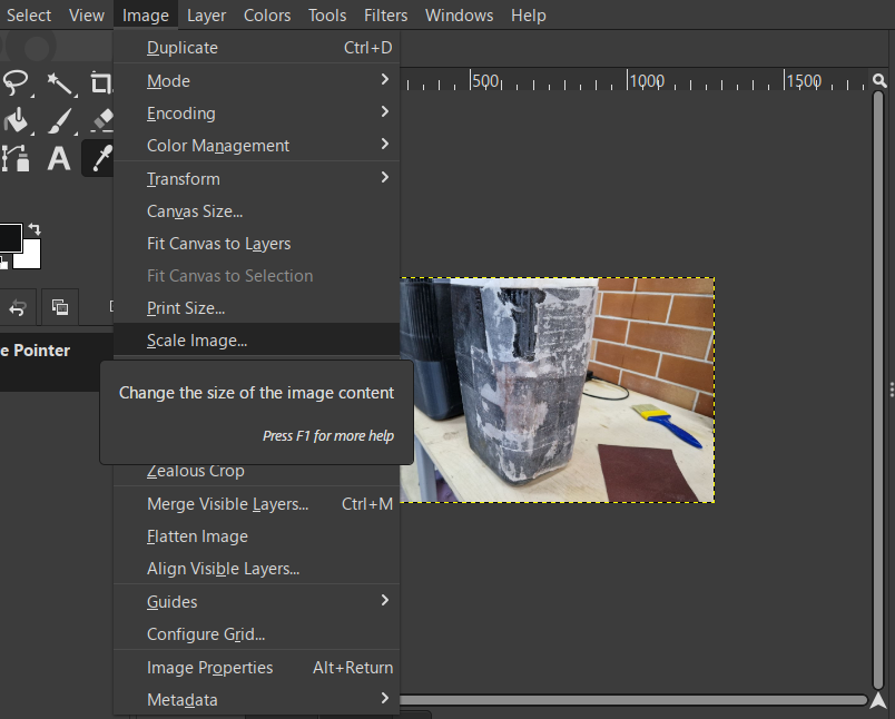
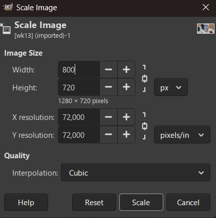
- Scale Image - In the top left corner I clicked on the image, then in the tab I clicked on the scale image, I changed the width to 800 pixels maximum, then I clicked on the scale.
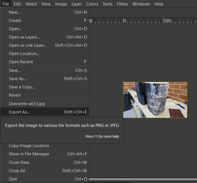
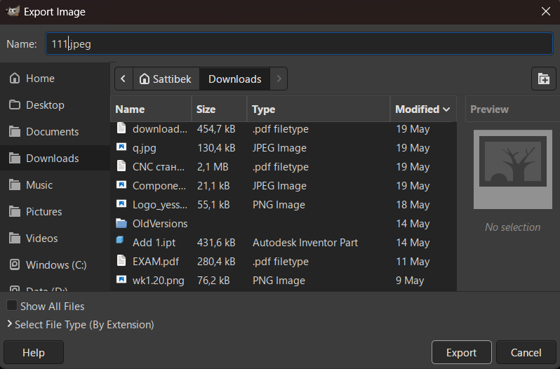
- Export As… - The image is ready, I chose the save folder and exported it in JPEG format.
The compression significantly reduced storage requirements and improved website performance without noticeably affecting image quality.
The screenshots used in this documentation were originally exported at high resolution. To reduce website loading time and repository size, the images were optimized before uploading.

I used Inkscape to resize and optimize the images. For editing and compressing images used in my documentation.
Reducing the image size helped decrease storage requirements and improved page loading performance without significantly affecting image quality.
- Created a new document
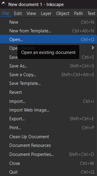
- In the file tab, click open and select the image file.
- Used the tools from above for movement and manual editing of the image.
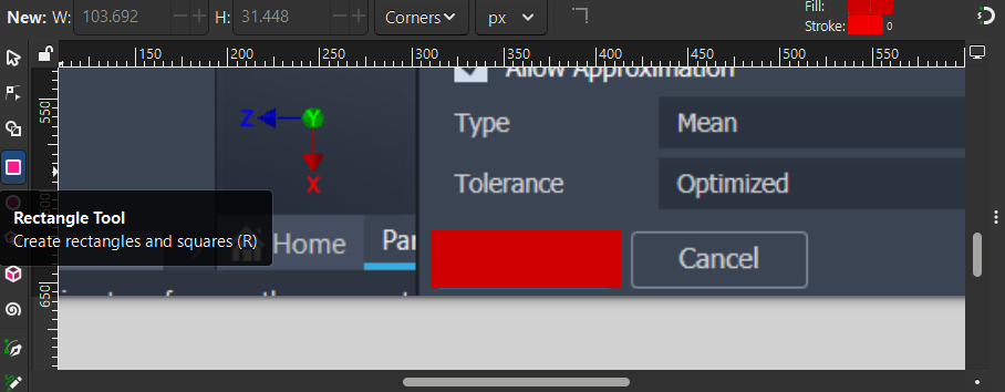
- I used the rectangle tool from the left toolbar and drew a rectangle.
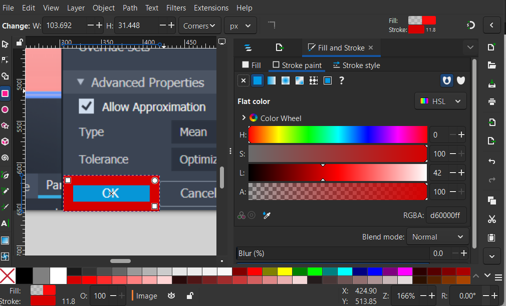
- I opened the fill and stroke, in the fill part I filled it with red and set the fill to 0, and in the second part of the Stroke point, I set the stroke color to red.
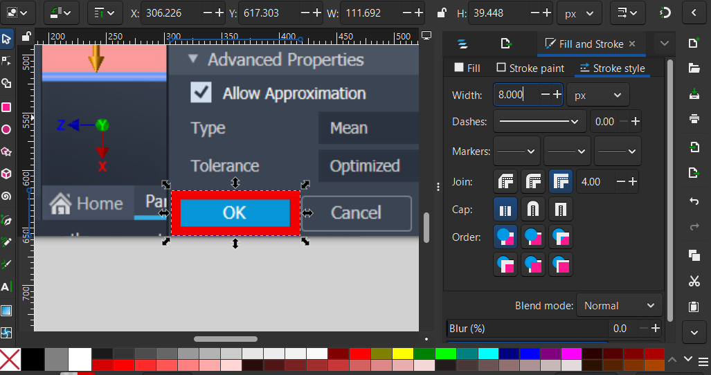
- I went to stroke style and set the thickness to 8 pixels.
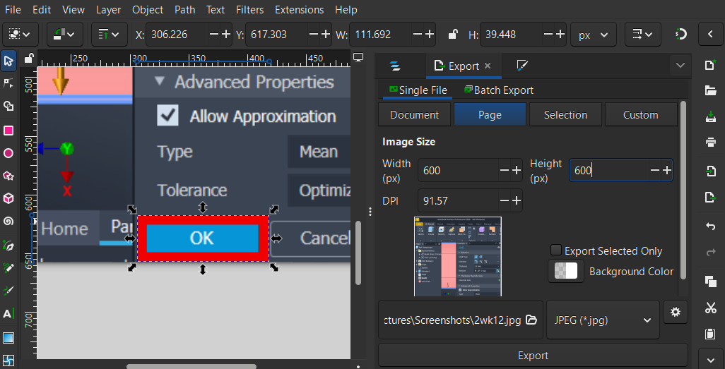
- Next, I clicked the export button in the file tab. I filled it out as width 600, height 600, and selected the .jpg format. And the file is ready.
Video Compression
To document the modeling process, I recorded a short demonstration video and exported it in MP4 format.
Before uploading, the video was compressed using Clideo. The compression process reduced the file size while preserving sufficient quality for online viewing and documentation purposes.
- Upload a video - I clicked the compress button, selected the file from my files, and expected a small download.
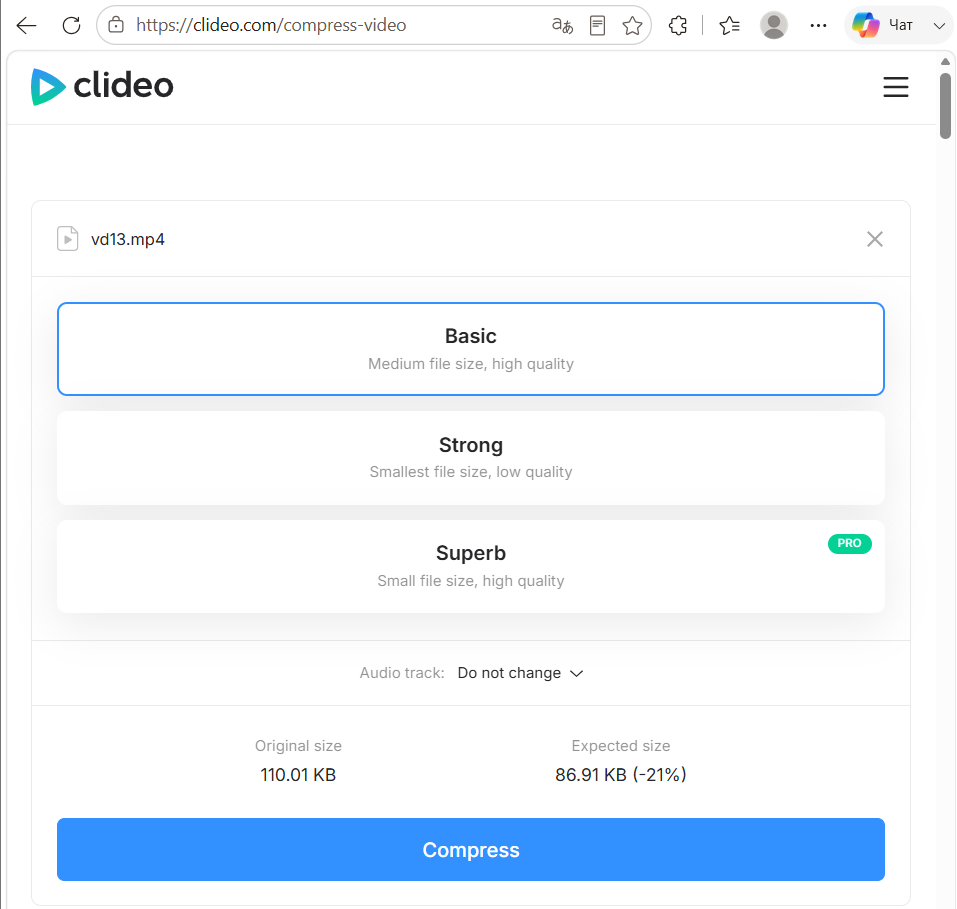
- Compress the file - The file was downloaded, I chose the basic option from three options, clicked on compress, then waited for the compressed file to be exported, and I received a ready-made compressed video file
Reducing the file size made the video easier to upload, store, and access through the project repository and website.
Reflection / Conclusion
This assignment helped me improve my understanding of the complete CAD workflow, from creating 2D sketches to generating complex 3D models. I learned how parametric design simplifies modifications and how manufacturing constraints influence design decisions.